We have seen a lot of USB Type-C over the years. First, it started showing up on our computers, and its usefulness started to show up. Right now, even our phones are choosing it over the old Micro USB. But what about our devices? Well, they have also seen some changes in ports, to a point where even the new Arduino and ST boards are starting to launch with one, such as the Arduino Potenta H7. The USB Type-C is here, but there is still a lot to be done for the overlooked devices that we use on a daily basis, either in our projects or in the electronics lab. A great example is a LiPo charger. There are many Micro USB options, but what about USB Type-C? Well, now there is!
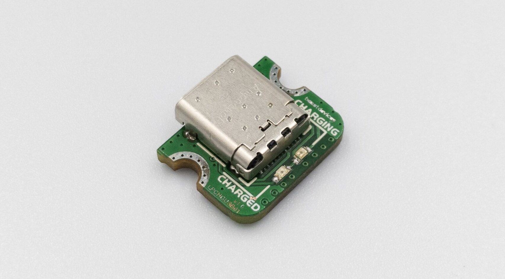
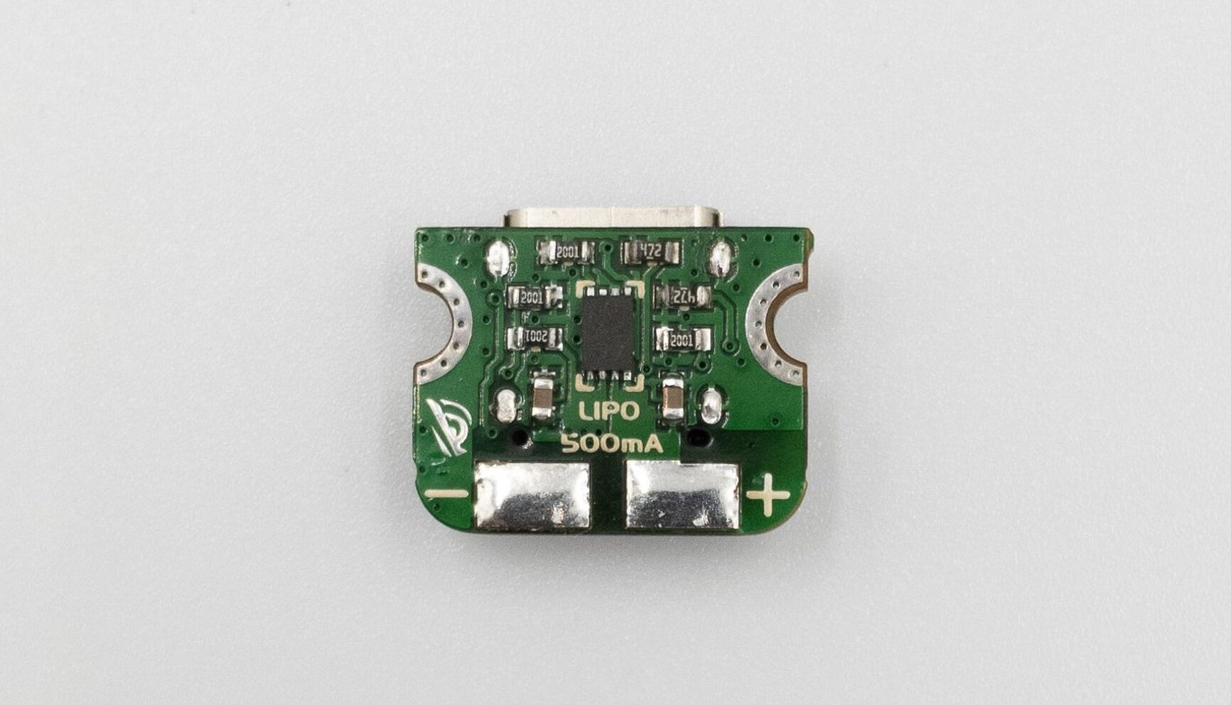
Looking at this issue, the makers over at Beast Devices decided to do something. A new LiPo battery charger with USB Type-C capabilities and they did so in great style, as they turned it into the smallest and most simplistic as they could, and it is amazing. By looking at it, you can appreciate its small size (which is 13.5 mm x 16 mm), where the front is dominated by the USB Type-C connector (a high-quality one from the company Amphenol) and two status LED’s (red – charging and green – charged), along with mounting cutouts designed for M2.5 and M3 screw sizes. On the back, there is a lot more going on: in the middle, there is the MCP73831T-2ATI/MC, a battery charger IC in the small DFN package, capable of delivering 500 mA charging current, surrounded by the necessary passive components and the two connectors for your battery. Overall, you can see that this PCB cannot fit anything else, and their efforts to make such a small board should be recognized!
There is a lot going on the back of this device
Regarding where you can find this, the answer is simple: the USB Type-C charger is available on Tindie for $14.90. Now, you might be thinking that it is a salty price for a LiPo battery charger, and you might be right, the components are not very expensive, but that would be undermining their effort to make something so small, and that should be recognized. There are cheaper options, but usually, they come at small charging currents and definitely at a size ten times bigger! One example is the SparkFun LiPo Charger Plus, coming at around $9.95, offering also a battery connector, for a bigger size. The bottom line is, if you are not willing to compromise on size, you should definitely get the one from Beast Devices. If not, then you have cheaper options.
PartKeepr is one of the best known part invertory systems, and made it open source for anyone else to use. PartKeepr was developed with usability as its first priority. You can sort and filter by virtually any field, drag and drop parts into any category, hide and show additional fields as required and customize the layout of PartKeepr as you require.
CSV and Excel export as well as CSV import helps you to interface with external systems. Barcode Scanner support allows you to retrieve part data without touching the keyboard but daily backups take very long due to the thousands of folders and files the software creates. The installation files have over 113,000 folders.
So Brian Dorey decided to build his own Part inventory management system called Part Finder.
The development of the Part finder has reduced the timing of daily backups among other advantages. Part Finder is the most advanced fitment search app for BigCommerce stores. It helps your customers find what they’re looking for, then uses those search results to analyze & grow your business. The following are other benefits of Part Finder:
Helps customers find products faster & more accurately
Increase conversion & customer confidence
Reduces support staffing & product returns
Improves marketing efforts
Analyzes trends for inventory prediction
The Part Finder is an ASP.Net C# project and use SQL Server Express (or full) for the database and can also be run on a Windows desktop / laptop running Windows 10 Pro with the installation of the IIS services and SQL Server Express.
Now let’s take you through the installation process :
In SQL Manager, create a new database called PartFinder and run database.sql in partfinder/setup to create the database tables, views and add default data for footprints and part categories.
Create a new user for the database and give the following permissions: Connect, Select, Update, Delete, Execute.
Edit the web.config file in the PartFinder root and update the connection string MainConn with the username and password for your database.
In Internet Information Services (IIS) Manager, create a new website and set the folder path to the location you extracted the files.
If you are running this application on a public-facing connection or server, you need to create a login using an email address and password.
To add the first user, go to the /setup folder in your web browser and create your first user account to sign into Part Finder.
Delete the setup folder once the setup is completed.
The system can be used on an intranet or local machine without the login requirement by commenting out the following section in the web.config file:
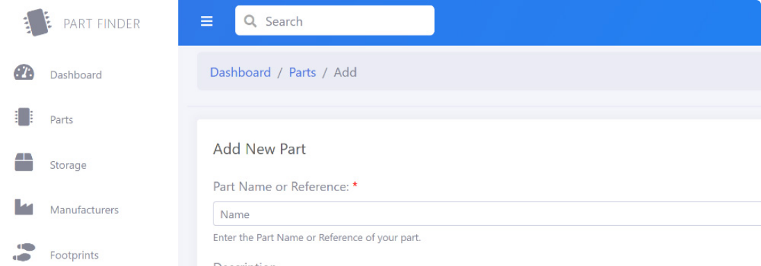
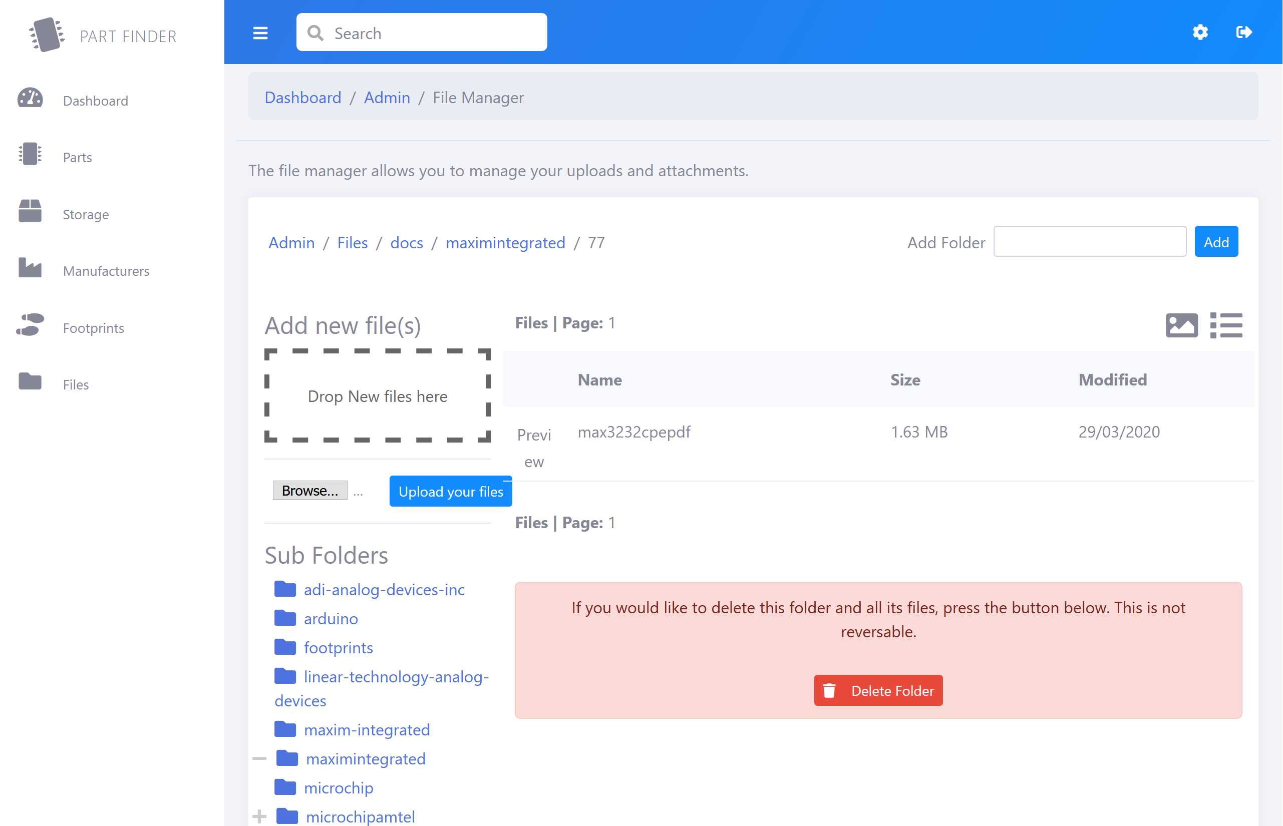
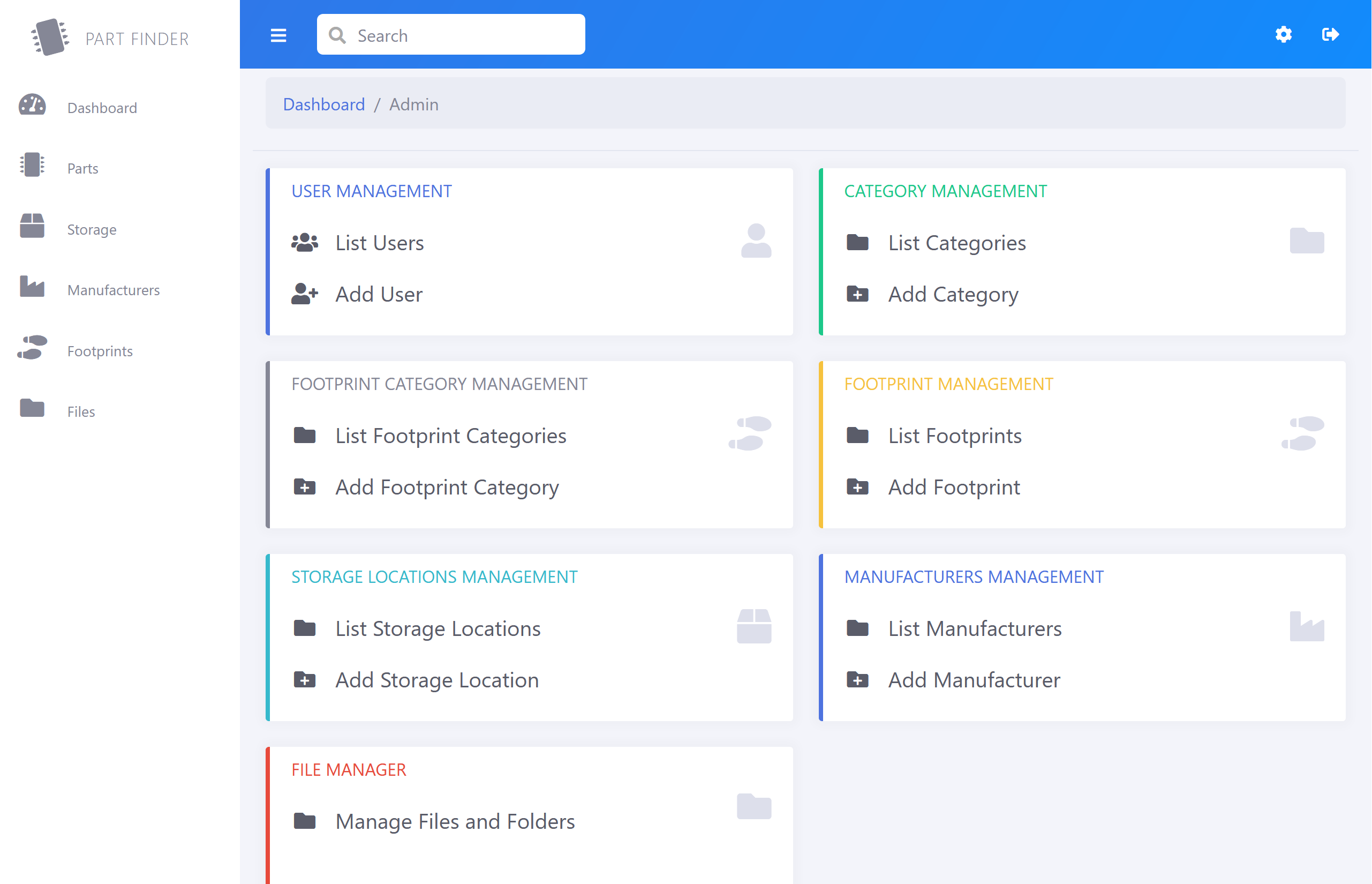
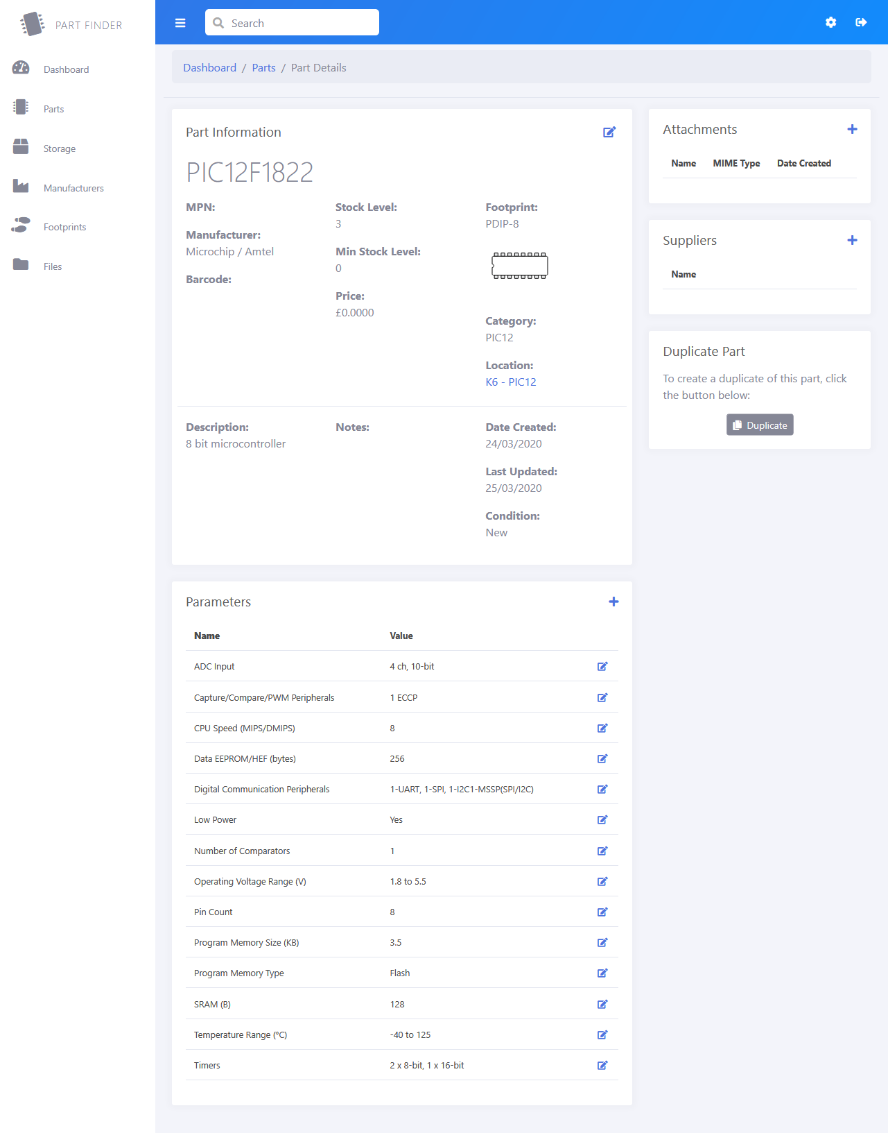
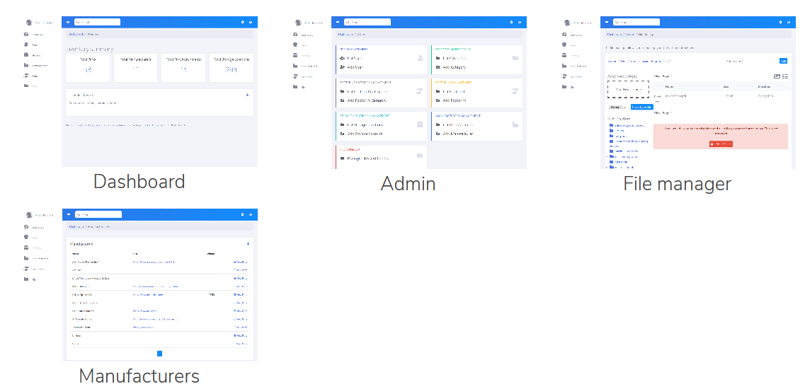
The admin section contains a file manager that allows you to create directories/folders and add files within the “/docs” folder in the website root. This will need to add read/write permissions for the IIS/User account on your server/computer for this folder. The Dashboard gives you an overview of the system with totals for Parts, Manufacturers, Attachments, and Storage Locations. It also lists any parts which have less than your low stock level available. The Parts section is where you manage all your components/parts with a tree-view or list view to find your parts and a parts details page with your item’s main details, attachments, suppliers, and parameters. You can also duplicate a part if you are adding similar new items.
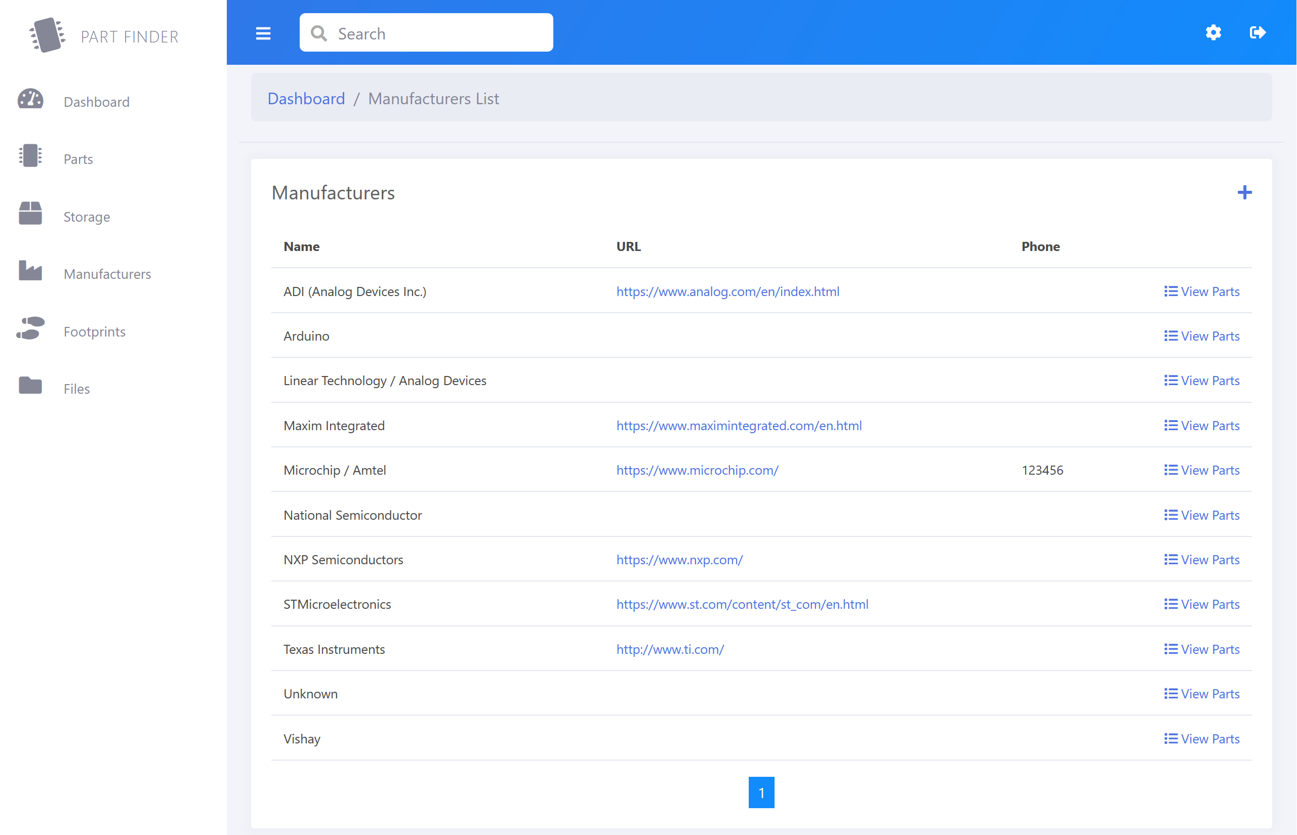
In the Storage section, you can add and edit your storage locations before adding new parts for each location. You can add storage locations one at a time or use the Storage Location Grid page to bulk add locations such as storage drawers etc. These can be edited in the admin section (cog icon). In the Manufacturers section, you can add and edit component manufacturers before adding new parts. These can be edited in the admin section (cog icon). In the Footprints section, you can add and edit your component footprints before adding new parts. These can be edited in the admin section (cog icon). The file manager allows you to view the /docs folder on your PartFinder website. You can add upload new files and create folders, view, and delete files.
Please note if you delete a folder or file which is linked to an existing part, it will not remove the database record for the file. The admin section has Add, Edit, and List pages for Users, Categories, Footprint Categories, Footprints, Storage Locations, Manufacturers, and the file manager.
You can visit Brian Dorey’s website for more information
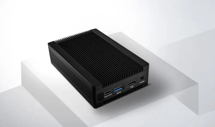
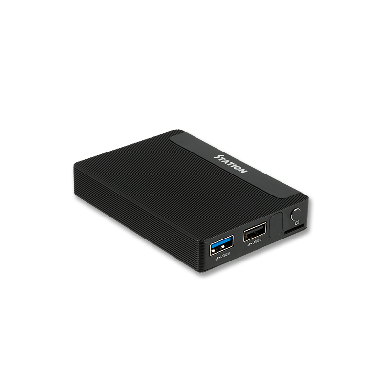
T-Chip has recently introduced two fanless mini-PCs – Station P1 and M1 – that are similar in some sense and powered by Rockchip RK3399 hexa-core and RK3328 quad-core processors respectively.
The Station P1 and M1 are affordable and compact mini PCs designed for ease and convenience of users. They are about the size of a credit card, so they are small and portable enough to be carried everywhere around in the pocket. They also have a good airflow design that allows for effective heat dissipation as well as support for various operating systems, multiple bootup ways, powerful hardware decoding, and a variety of expansion interfaces for more possibilities.
The two mini PCs can run the company’s Station OS in both desktop and media modes, as well as Android 7.1.2 and Ubuntu 18.04, enabling users to operate multiple systems freely.
Key Features and Specifications of Station P1:
Rockchip RK3399 hexa-core processor with two Cortex A72 cores @ up to 1.8 GHz and four Cortex-A53 cores
Mali-T860 MP4 GPU that supports up to 4K H.265 10-bit 60fps video decoding
4GB LPDDR4 dual-channel 64-bit RAM
32GB eMMC flash (with optional 16GB/64GB/128GB)
16MB SPI flash
1x MicroSD card slot
HDMI 2.0a up to 4Kp60
DisplayPort 1.2 up to 4Kp60 (via USB Type-C port)
Dual display support up to 4K + 2K
3.5mm audio jack
Digital audio via HDMI
Gigabit Ethernet
2.4GHz 802.11b/g/n WiFi 4
Bluetooth 4.2 (BLE)
1x USB 2.0, 1x USB 3.0 and 1x USB 3.0 Type-C OTG ports
IR receiver
12V/2A power supply via 5.5/2.1mm power jack
Dimensions – 124.4 mm x 79 mm x 31.6 mm
Key Features and Specifications of Station M1:
Rockchip RK3328 quad-core Arm Cortex-A53 @ 1.5GHz
ARM Mali-450 MP2 GPU that supports 4K UHD VPU for H.265, H.264, VP9 video decoding.
2 GB or 4 GB of DDR3 RAM
eMMC 5.1 flash (8GB to 128GB)
1x MicroSD card slot
1x HDMI 2.0a up to 4Kp60, HDCP 1.4/2.2
1x 3.5mm AV port with CVBS + stereo audio output
1x Gigabit Ethernet
2.4GHz 802.11a/b/g/n WiFI 4
Bluetooth 4.2
1x USB 2.0 host port
1x USB 3.0 port
1x micro USB Type-C OTG port
Recovery button, Power key and IR receiver
5V power supply via USB Type-C port
Dimensions: 93.8 mm x 65 mm x 15.8 mm
P1 sells for $120 while M1 goes for $75. Both are shipped with power supply, remote control, and USB & HDMI cables, but the M1 adds an external antenna.
The company also offers a basic pack of the Station P1 mini PC that adds a 15.6-inch Type-C display for $289 (4GB RAM / 32GB storage) or $339 (4GB RAM / 128GB storage).
Amyotrophic lateral sclerosis (ALS) is a chronic disease that affects the nervous system and causes a decline in muscle control. Symptoms of ALS may be minor in the early stages of the disease but get dramatically worse with time as people with ALS find it more and more difficult to control the muscles necessary to speak or move limbs. It gets so bad that they lose their power to communicate with others around them.
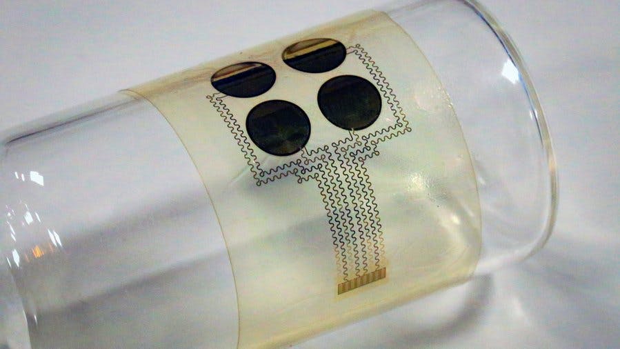
That is why a team of researchers from MIT who hope that their new device would help patients to communicate in a more natural way without having to deal with much weight, has taken it upon themselves to develop a wearable patch equipped with sensors to help people suffering from ALS communicate better.
The patch is attached to a patient’s face and used to capture even the smallest facial movements such as a twitch or a smile. The device consists of four piezoelectric sensors made of aluminum nitride which are able to detect mechanical deformation of the skin and converted into an electric voltage that can be easily measured. So, with small movements that are measured and interpreted by the device, patients can communicate a number of sentiments, like “I’ hungry”, “I love you”, etc.
The wearable sensor is comfortable on the skin and can be worn for extended periods of time.
“You can camouflage it with makeup to match your skin tone and nobody would think that you have something on your skin”,
says Canan Dagdeviren, MIT’s LG Electronics Career Development Assistant Professor of Media Arts and Sciences.
The team was able to create a machine learning model that could differentiate between three unique expressions: a smile, an open mouth, and pursed lips. They used the algorithm to test the device on two patients and achieved about 75 percent accuracy in distinguishing between these different movements. So they have gone ahead filed for a patent on this technology and they now plan to test it with additional patients.
Apart from helping patients communicate, the device according to the researchers, could also be used to track the progression of a patient’s disease or know the extent to which the treatments they are receiving are effective.
“Instead of just relying on the patients to report that they feel better or they feel stronger, this device could give a quantitative measure to track the effectiveness,” they said.
This patch would be very affordable, costing only about $10, so it will become much more accessible than other technologies designed for similar purposes.
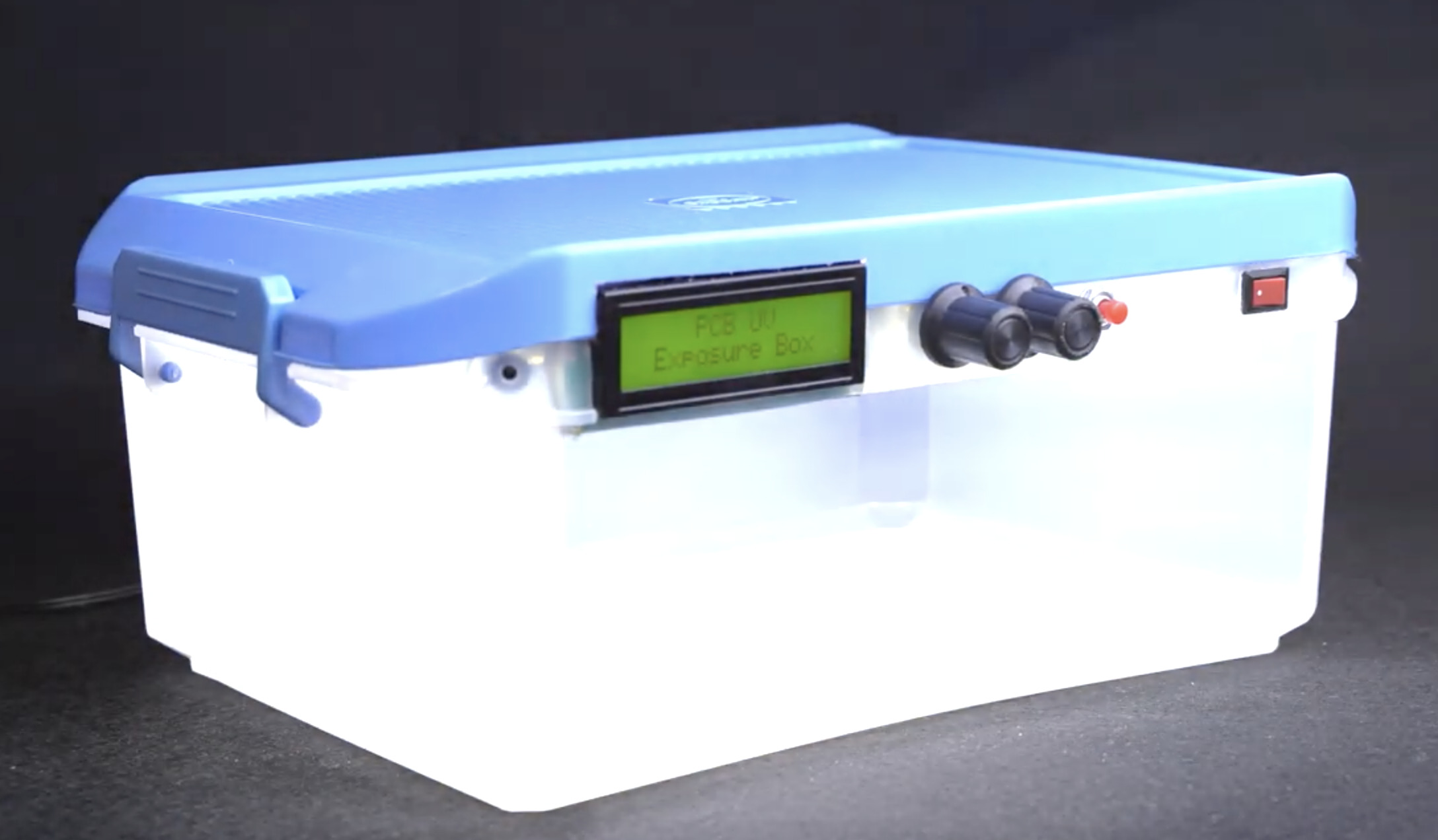
Printed circuit boards make the creation of electronic devices in a repeatable and reliable manner a possibility. However, due to factors such as long turnaround time, cost, and other challenges associated with making PCBs through established fab houses, electronics hobbyists and prototype engineers usually turn to DIY approaches of PCB development like the heat transfer method and the UV-based design transfer method. While the UV-based system with pre-sensitized PCBs is more reliable, the heat-based system is far more popular due to the complexity and cost of setting up the UV chamber required for a UV-based system. To remove these barriers and make the pre-sensitized PCB approach accessible to everyone, Youtube DIY Star; “Techbuilder“, recently shared the process of creating a DIY Digital PCB Exposure Box in a video.
The Exposure Box which was made from a recycled components box, had it’s top lined with LED strips that are turned “on” or “off” by an Arduino Nano based control system. The control system makes use of time duration, preset by the user via a potentiometer, as the control variable. It turns off the light when the preset time has been attained, ensuring the PCB is not overexposed.
Today’s tutorial will lay out the project in a step-by-step manner to make it easy for you to replicate.
Ready? let’s go!
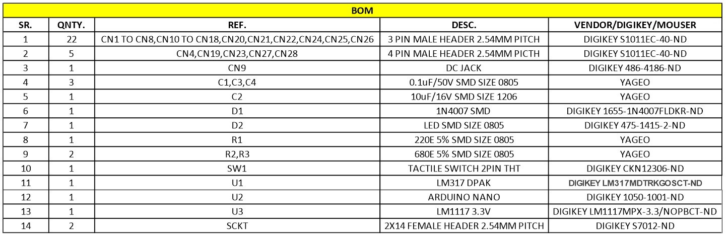
Required Components
To build the DIY Digital PCB Exposure Box, you will need the following components:
While you may be able to salvage some of these components from old projects/a dumpster dive, the components can also be bought via the links attached to them. In case you are not able to get the exact components, the project is flexible and almost all of the components can be swapped with close alternatives. For instance, you can decide to use the cheaper and smaller Arduino Pro-Mini instead of the Arduino Nano.
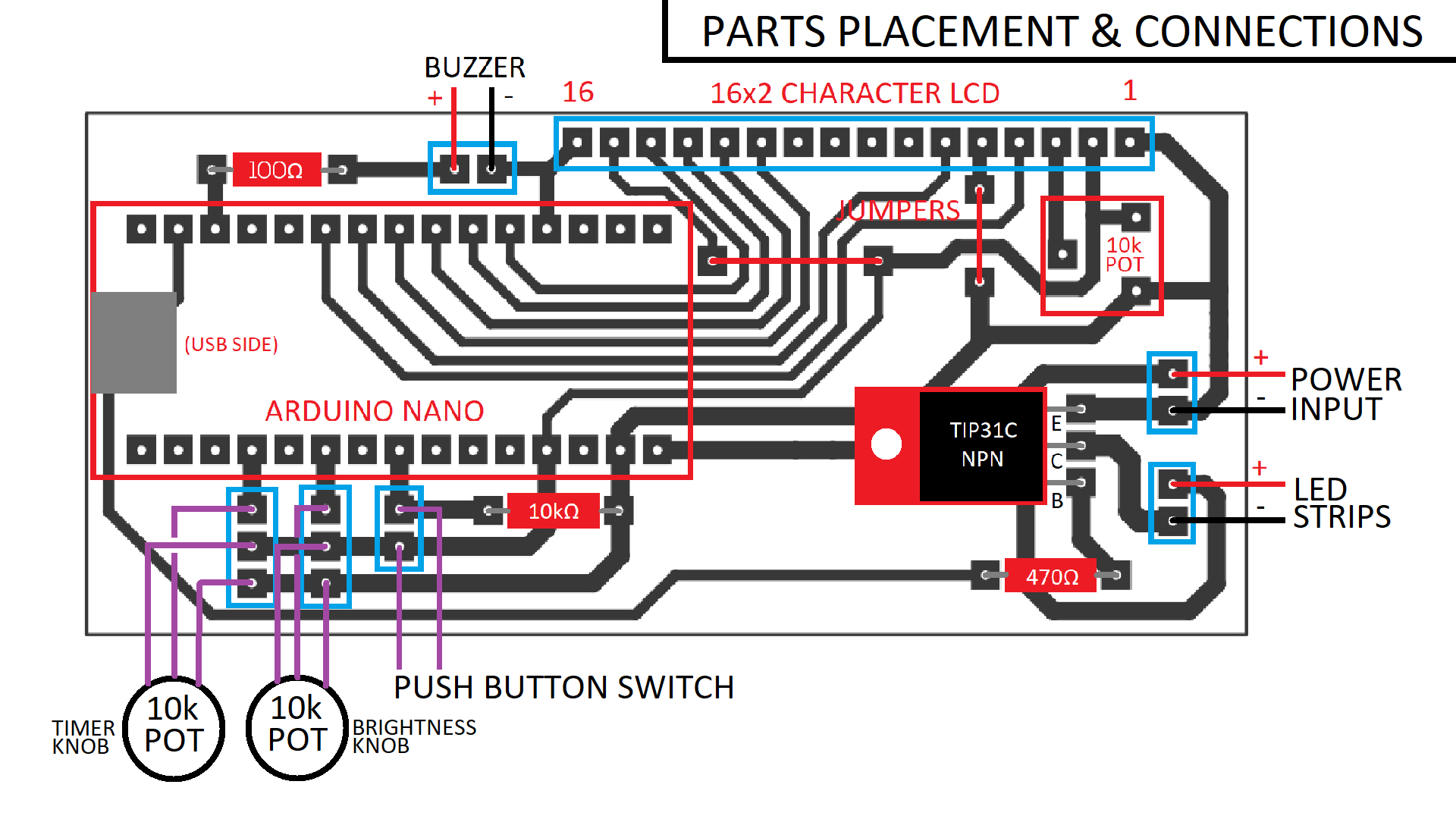
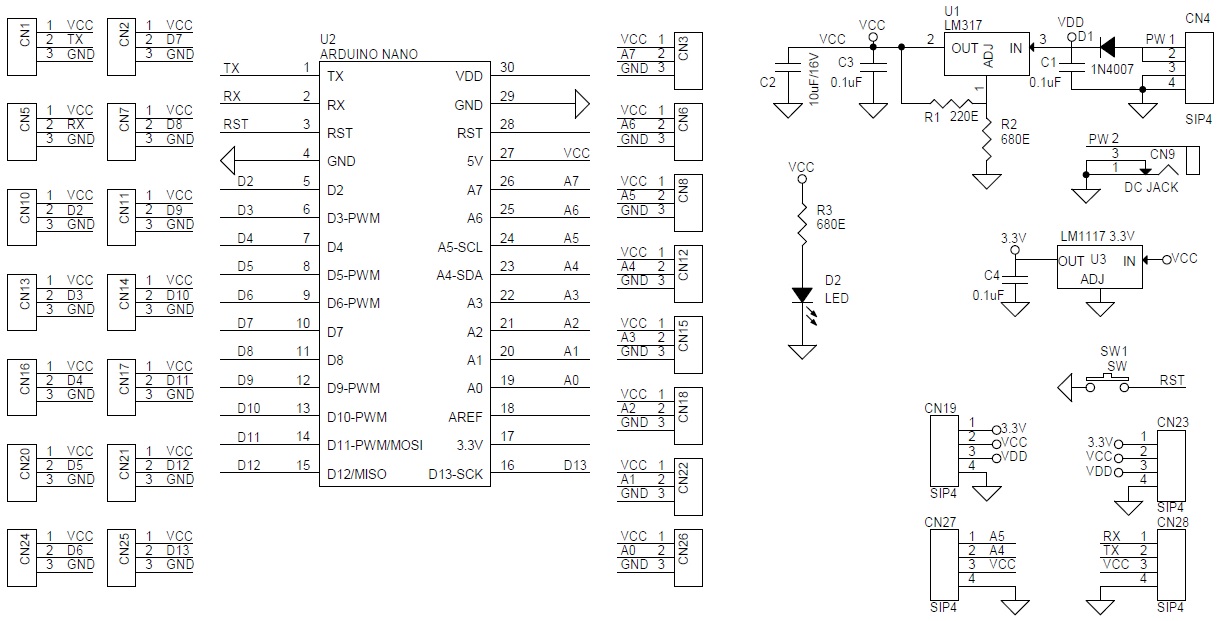
Schematics
The schematics for the project is provided in the image below. The project was implemented on a PCB to make it more compact and easy to mount on the enclosure, but by carefully following the schematics below, you should be able to replicate the project on a veroboard or breadboard.
The schematics and PCB were created using Proteus and the project file with the schematics and PCB is attached under the download section to make it easy to replicate.
Project Enclosure and Assembly
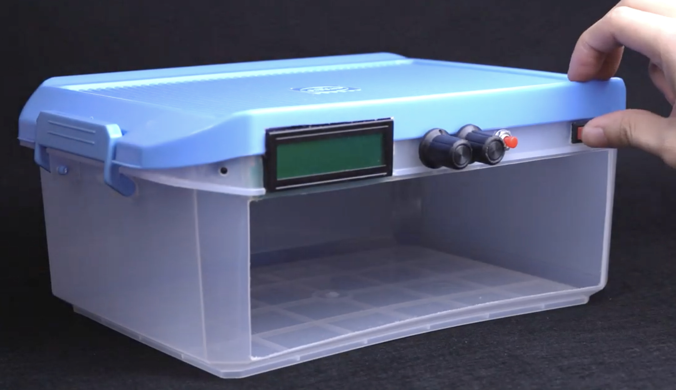
The enclosure is an important part of this project and it makes sense that Techbuilder made use of components box, as they can be easily bought from any electronics component store. But just in case you are unable to get your hands on the exact kind of box, you can make do with any kind of box with a good opaque top. A wooden enclosure should also work great.
With the enclosure secured, follow the steps below to put it together.
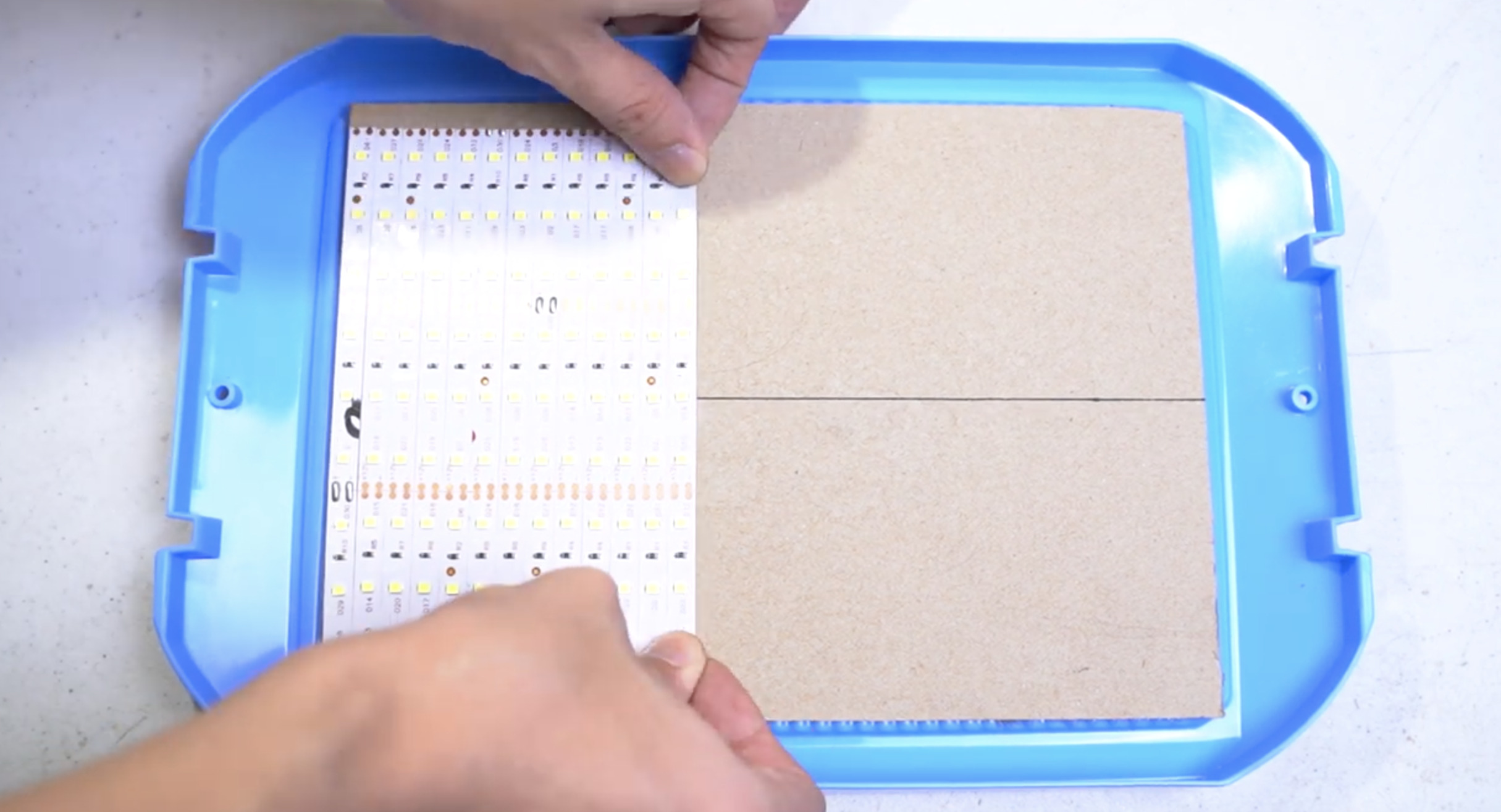
1. Prepare the top/cover of the enclosure. If the surface is not perfectly flat, you can put a layer of cardboard or any other material to make it flat.
2. Based on the width (or length, depending on the orientation you prefer) of the lid, cut the LED strips into pieces with equal length. Peel the cover off the back of the LED strips to expose the sticky side of the strips and gently mount the strips on the lid of your enclosure, ensuring there is little or no space between the strips.
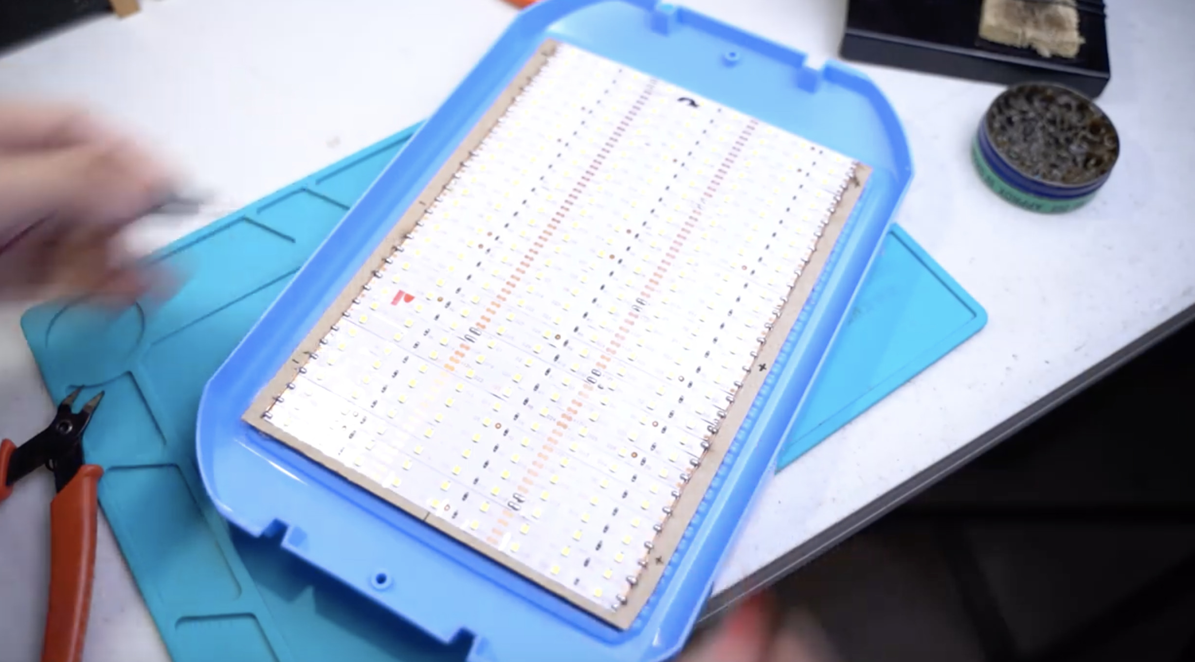
3. Next solder the positive leads of the strips together on one side and the negative terminals together on the other side of the box. Soldering on different sides reduces the chances of shorts.
With this done, power the LEDs up with a 12VDC/2A supply to be sure there are no shorts. If your connections have been properly soldered, all LEDs should come on.
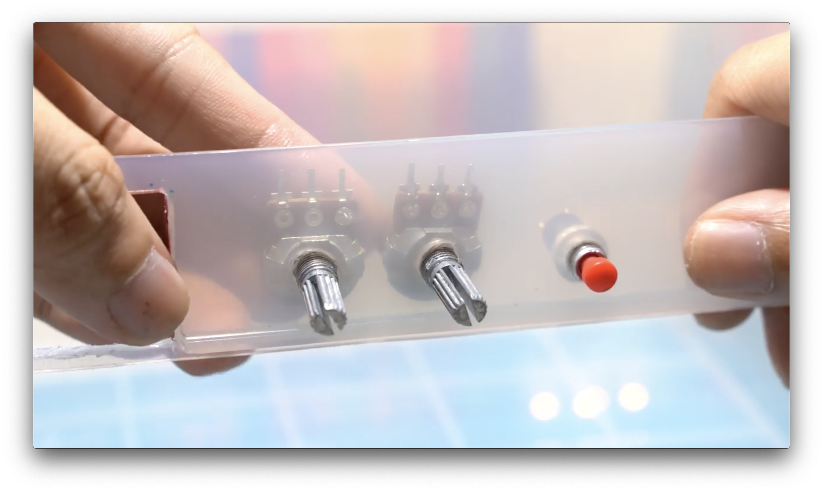
4. Next, you need to cut out holes for the screens, switch, and other elements that the users will interact with. You can do this with a CNC machine or a combination of drills, files, Dremel tools, and hot glue.
5. Connect all components and mount the external components in the holes made. feel free to use Hot glue to secure things in place where necessary.
With all this in place, your enclosure should now be ready and look like the image below.
Code
With the enclosure ready, the next step is to write the code and upload it to the Arduino board. The operations of the device are quite straight forward; allow the user to set the desired exposure time via the potentiometer, turn on the LEDs, and initiate the countdown process with the progress being displayed on the LCD. When the preset time is reached, turn off the LEDs and initiate a beep on the buzzer so the user is notified.
To turn these these patterns into code, the Arduino IDE was used and since most of the heavy lifting associated with the code has to do with displaying data on the LCD, the Arduino LiquidCrystal Library was used.
As usual, I will do a quick breakdown of the code, explaining the concepts/parts of it that I feel might be difficult to follow.
The sketch starts with the include statements for the liquid crystal library along with a declaration of an instance of the library.
Next, variables to hold different parameters including maximum countdown time, among others are declared and initialized.
//-------CONFIGURABLE PARAMETERS-------//
int
maxTime = 1200,          //Maximum countdown timer time (in secs)
buzzerFreq = 1000,       //Buzzer frequency (Hz, Change to customize tone)
glowDelay = 10;          //Change this to increase LED glow rate (0-200)
Next, system variables that are used to store different data during runtime are declared and initialized.
We start by setting the pinMode() of the output pins and initializing the LCD, after which some initialization and version control information is displayed.
This is where the functionality of the exposure box is defined and implemented. The system waits for the user to set the duration and brightness parameters and updates the display in realtime based on the values. Once the start button is pressed, the last duration valued set is stored, the LED is switched on and the exposure process starts. The duration is used for a countdown timer, and once it hits zero, the exposure process is halted by switching off the LEDs.
To restart the process, the user will have to press the reset button, set the duration and brightness, and press the button again to start the exposure process again.
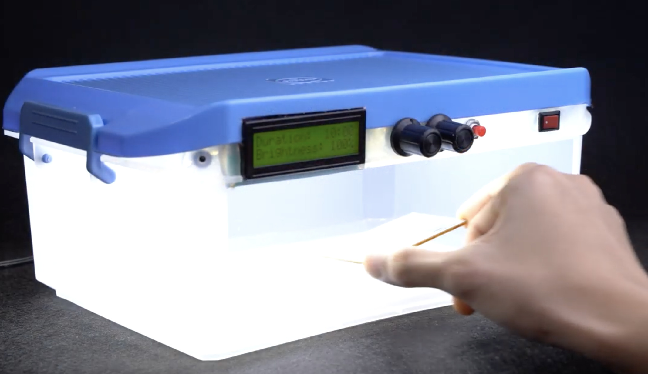
With the code complete, connect the Arduino nano board to your computer and upload the code to it. Ensure to select the right board type and COM port as the case may be.
After the upload, power up your device. You should see the LCD come up with the initialization messages being displayed. Feel free to test things out with any design, you should see more efficient design transfer than with heat or any other method.
That’s it. Your very own PCB Exposure BOX. Feel free to reach out via the comment section if you have any questions about this build.
Project credit goes to Techbuilder, and a video version of the tutorial is available on youtube here.
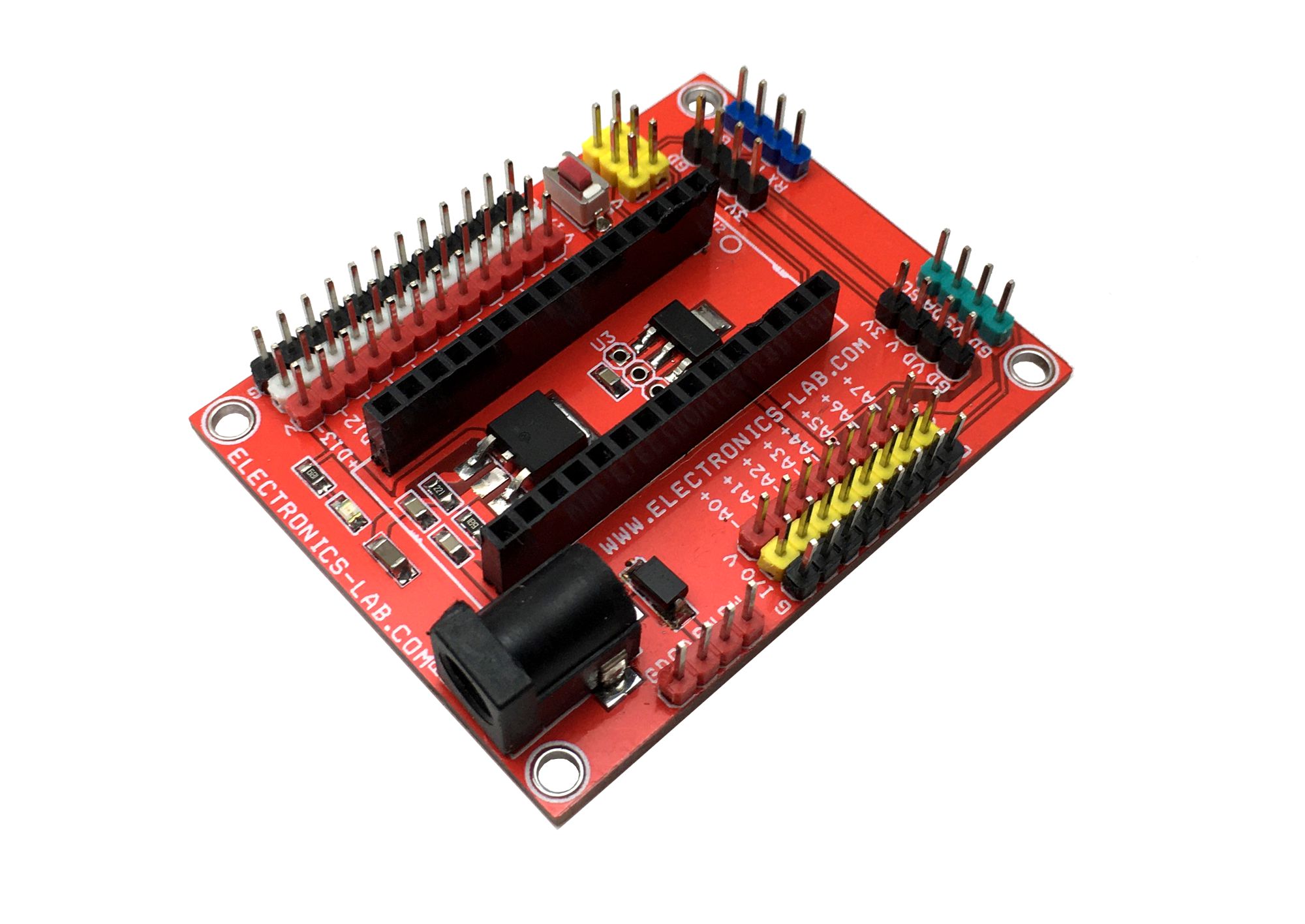
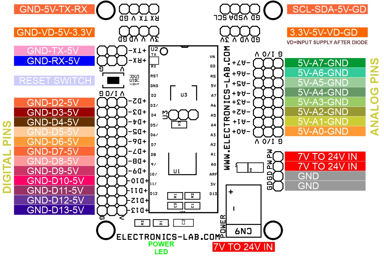
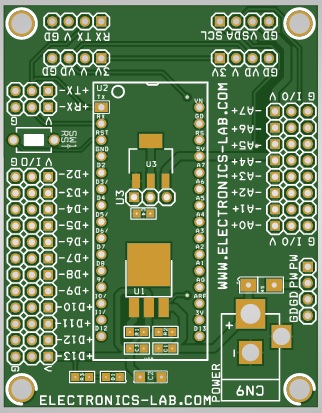
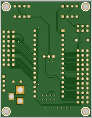
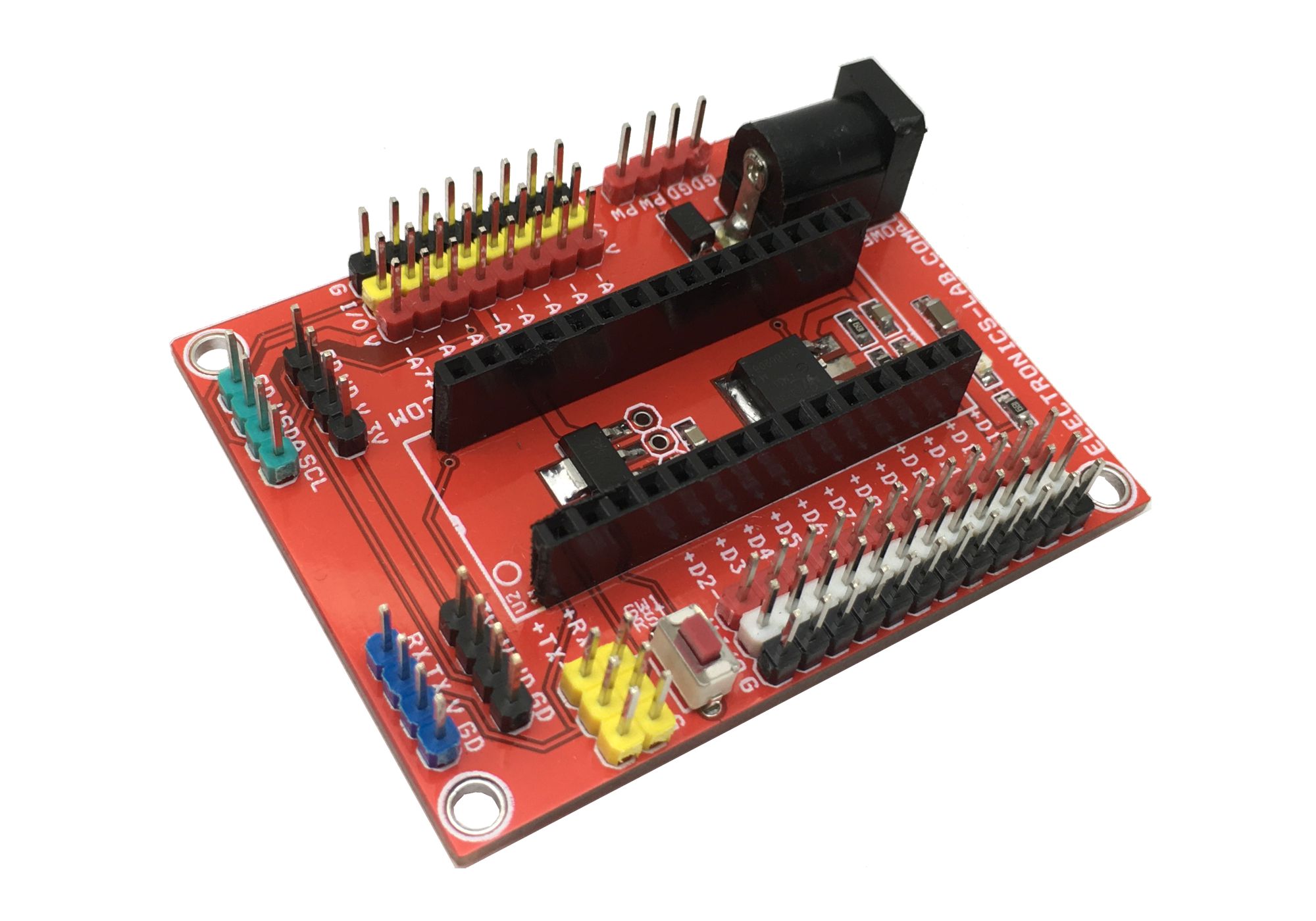
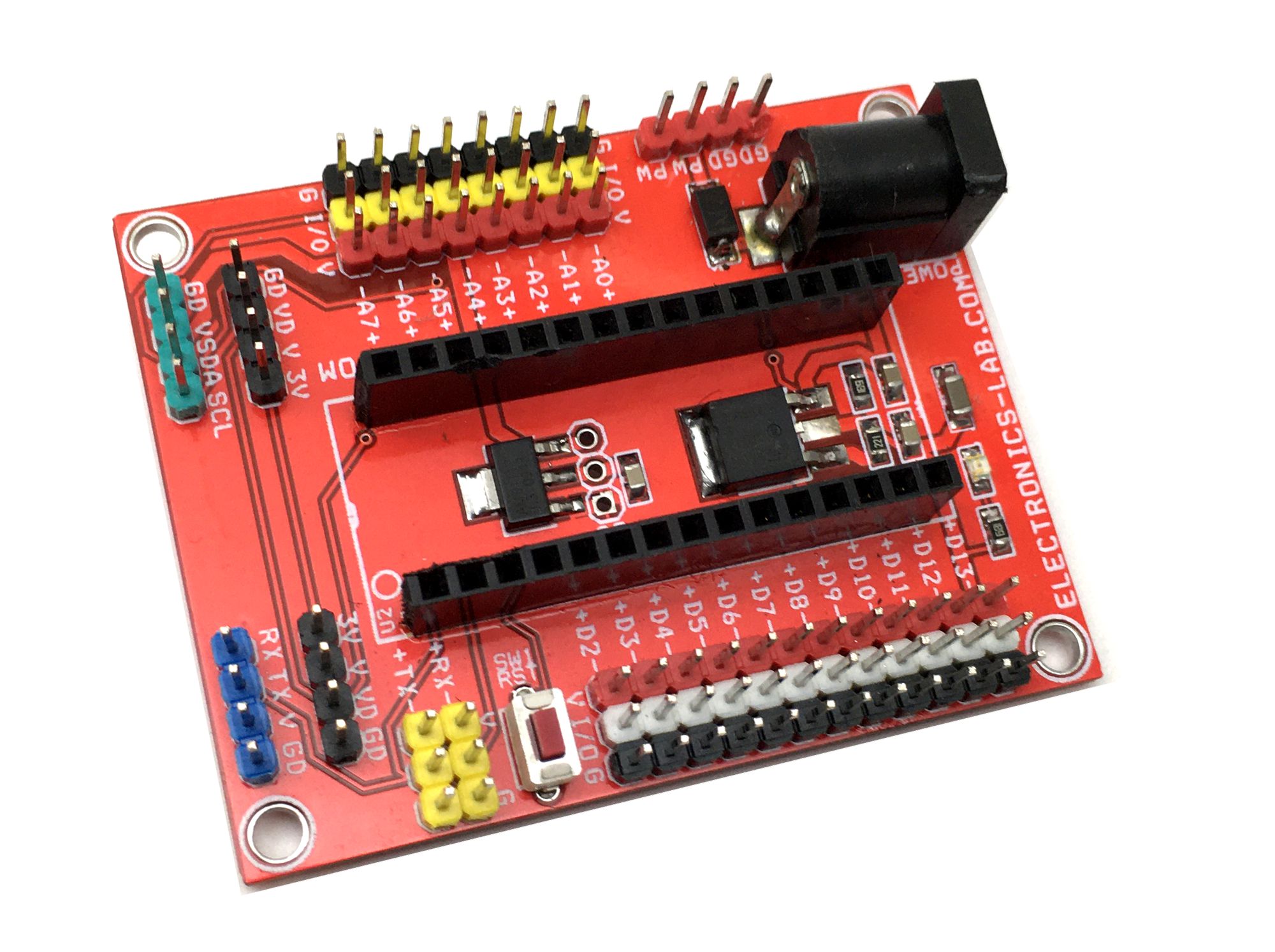
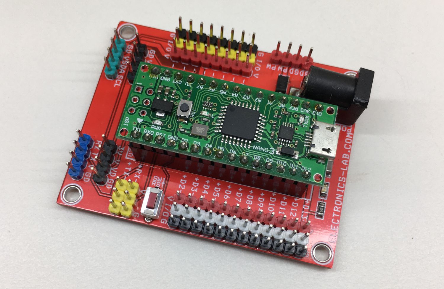
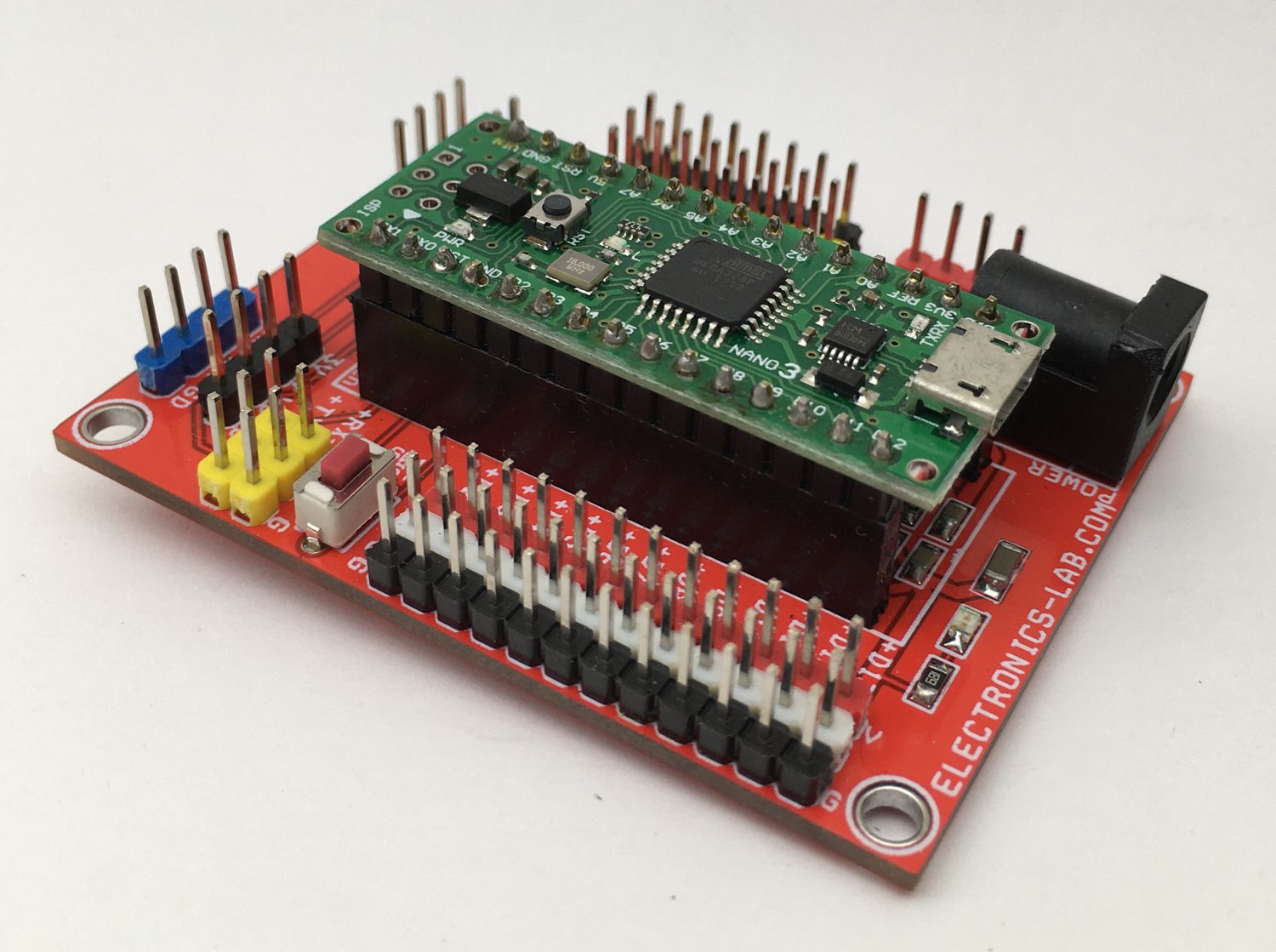
If you need to interface many devices and sensors to Arduino Nano, then, this project is for you. This is a Nano expansion I/O shield (breakout board) for the Arduino Nano. The board facilitates the easy connection between Arduino Nano and other devices. Each Arduino (I/O) Pin including the 5V DC and GND pins are available for easy connection to the sensors and other devices. The board enables the easy interface of many devices and sensors which includes various power voltage options. It provides several different options for power outputs and wide range of operating power supply input.
Features
All I/O pins including 5V DC and GND Pins (5V-I/0-GND)
On-Board TX/RX/5V/GND Connector for Serial Interface
On-Board I2C Connector (A5SCL- A4SDA-5V-GND)
2x Connector for Power Output: VD (Input Supply After Diode), 5V DC, 3.3V DC)
Supply Input 7V to 24V DC Using DC Jack or Header Connector
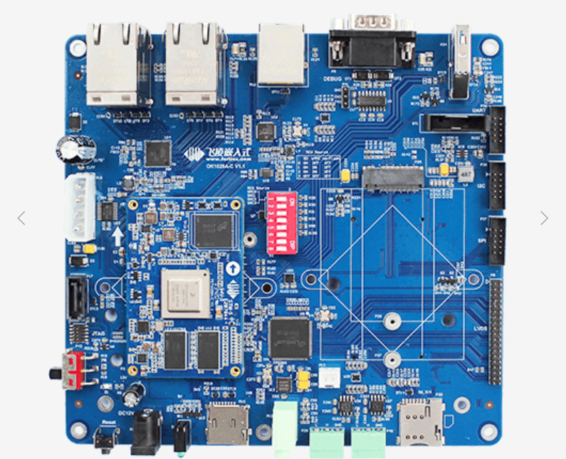
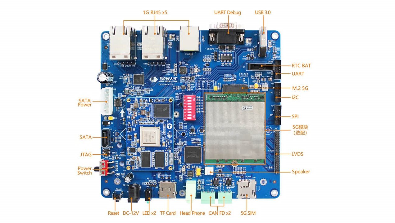
Forlinx has launched the OK1028A-C SBC, alongside a FET1028A-C module, which is designed based on Cortex -A72 featuring dual-core processor LS1028 A up to 1. 5G Hz. It features on-board 2GB DDR4 RAM and 8GB eMMC, can support 5 Gigabit Ethernet ports with TSN, 2 CAN-FD, USB3.0, UART, SPI, IIC, LVDS, TF card slot, SATA3.0, Headphone peripheral sources, and preserved with M.2 Key B for 5G module, mini PCIe for 4G module, and M.2 Key E for WiFi module. This is coming after Forlinx launched the headless OK1043A-C and OK1046A networking SBCs last year, which are powered by NXP’s quad-core, Cortex-A53 LS1043A, and quad -A72 LS1046A SoCs. However, the older SBCs do not enable video output, and you can only carry out configuration via a computer or laptop either through a UART interface or a web interface. To solve this problem, Forlinx released the new OK1028A-C which offers both a display interface and TSN (Time-Sensitive Networking).
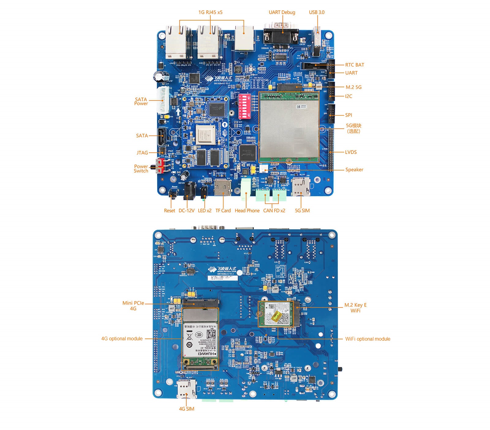
The OK1028A-C is based on the FET1028A-C, and features 5x GbE ports with TSN, a microSD slot, USB 3.0 host port, 2x CAN-FD ports, SATA III with SATA power, and a UART debug DB9 port. It features an LVDS interface which enables a PWM backlight control and a headphone jack and speaker. The OK1028A-C also enables a mini-PCIe slot that supports an optional 5G module and a M.2 B-key slot which supports an optional 4G module, both with the help of a SIM card slot. Available also is an M.2 E-key module with PCIe Gen2 which supports an optional, dual-band WiFi module. If offers additional interfaces like JTAG, SPI, 3.3V UART, and 2x I2C. The board offers a 12V jack with power and reset switches, 2x programmable LEDs, and an RTC with battery. The OK1028A-C SBC runs Ubuntu 18.04 with Qt 5.9.9 with the development of HMI applications. The OK1028A-C can be applied to Industrial IoT, TSN, SD-WAN, 5G CPE, edge computing, gateway, IP-PBX, smart factory, information security, intelligent transport, power management,
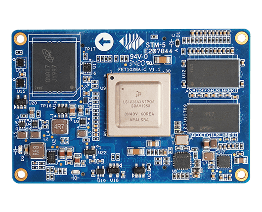
FET1028A-C module
The FET1028A-C module that drives the OK1028A-C SBC supports up to 5x 2.5GbE ports, as well as SerDes technology, but the SBC is limited to 5x 1GbE ports. This is compared to up to 6x or 7x 1GbE ports on the OK1043A-C and OK1046A, respectively. Those earlier boards also feature a 10GbE port and the OK1046A adds a 10GbE SFP+ or SFP-GE cage. The FET1028A-C features a 4-port TSN switch with 2.5GbE support and also support for a fifth 2.5GbE port and a GbE port. Five of the GbE ports can be configured by SerDes with SATA III and 2x up to 8GT/s PCIe 3.0 in various combinations with SGMII and QSGMII Ethernet. The 65 x 42mm FET1028A-C module also features 2GB DDR4 and 8GB eMMC, and enables DP 1.3 and eDP 1.4 interfaces up to 4Kp60. Other features includes up to 2x USB 3.0, 2x CAN FD, 4x UART, 6x I2C, 6x I2S, 2x SPI, and SD 3.0. The module has an operating range of -40 to 85℃.
Forlinx OK1028A-C specifications include:
FET1028A-C system-on-module
*SoC – NXP LS1028A dual-core Cortex-A72 processor @ up to 1.5GHz
*System Memory – 2GB DDR4
*Storage – 8GB eMMC flash
*Board-to-board connectors with
Display – DP1.3 and eDP 1.4, up to 4Kp60
Storage – 1x SATA III up to 6Gbps, configured by SerDes
Networking – Up to 6x Ethernet up to 2.5Gbps, TSN support, and 4-port TSN switch; 5x Ethernet ports can be configured by SerDes
PCIe – Up to 2x PCIe 3.0 interfaces up to 8GT/s, configured by SerDes
USB – Up to 2x USB 3.0 5Gbps interfaces
Various low-speed interfaces – 4x UART, 2x CAN FD, 6x I2C, 2x SPI, etc…
Supply Voltage – 12V DC (TBC)
Dimensions – 65 x 42 mm
Temperature Range – -40℃~ +85℃
The FET1028A-C and OK1028A-C SBC is available for an undisclosed price, buyers should bear shipping cost in mind. More information can be found on their product pages.
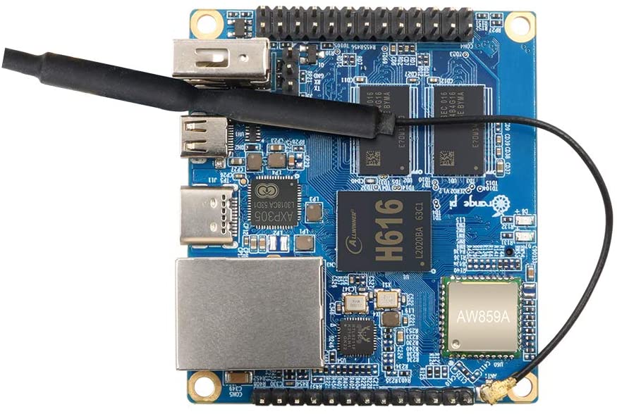
With the market being flooded by “Pi” branded products, it becomes hard to find out which ones deserve your attention and bring something new to the table, and not just impersonate the original Raspberry Pi models. This is as big of a rant you are going to get today, as we take a peek to the new Orange Pi Zero 2 and find out where it stands in this Pi world we live in.
The Orange Pi Zero 2 is an alternative to the Pi Zero, and has been unveiled over a year ago, but only now has started shipping orders. It build upon its predecessor by switching from an ARM Cortex-A7 based processor, the Allwinner H2, to a much faster, Cortex-A53 based Allwinner H616 (clocked at 1.5 GHz), which blows the Raspberry Pi Zero right out of the water in terms of performance for about the same price and a less rectangular, but just a tad bit bigger size, coming at a size of 60 x 53 mm (compared with the 66 x 30 mm of the Raspberry Pi Zero). Besides that, it offers you the option for 512 MB or 1 GB of RAM, and upgrades its predecessor Orange Pi Zero in almost every level: processor, RAM, adds Bluetooth 5.0, faster Wi-Fi and ethernet, provides a micro HDMI interface and switches its power to USB type-C, instead of micro USB.
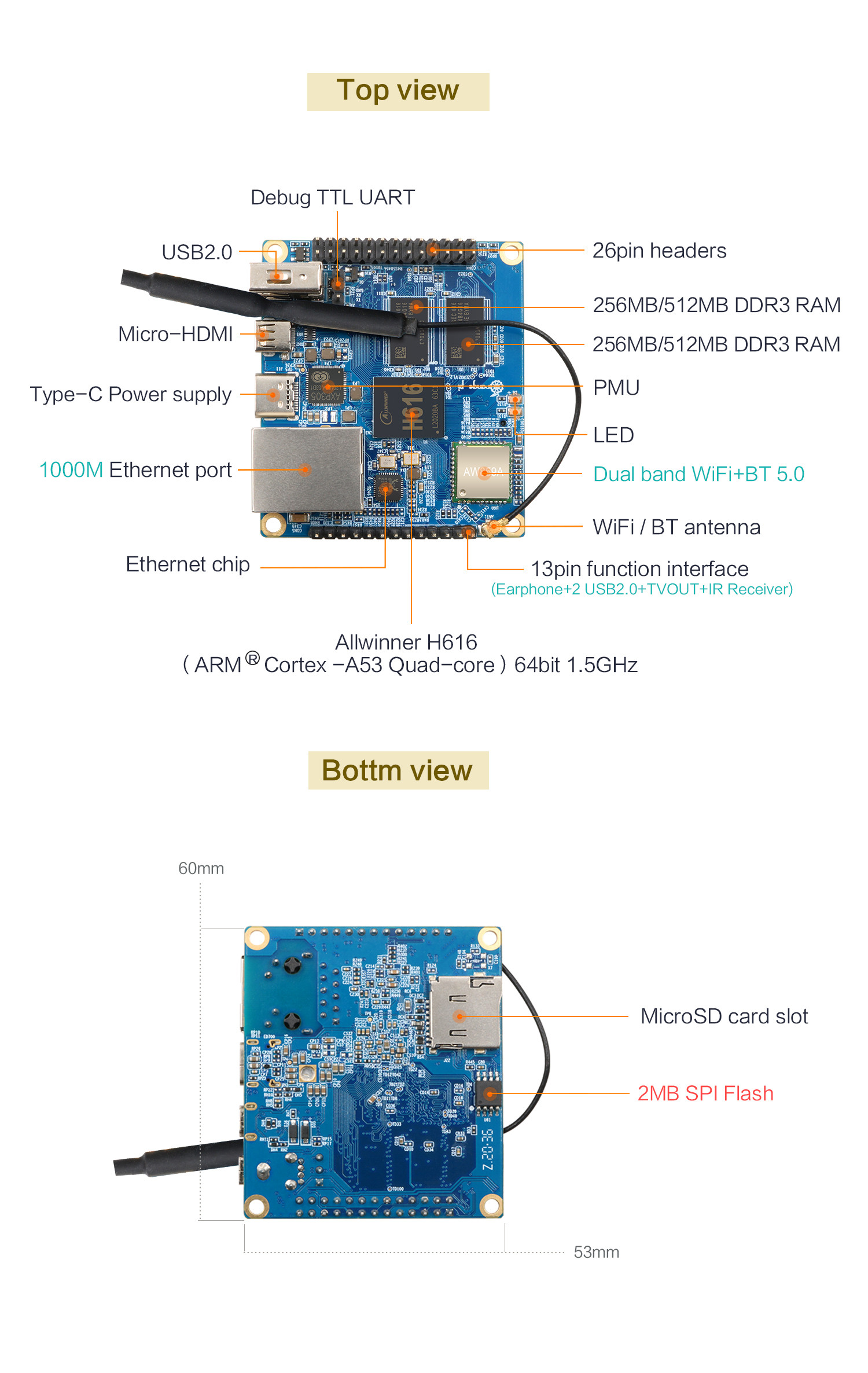
Looking at its specs in greater detail:
Allwinner H616: 64-bit quad-core ARM Cortex-A53 processor, clocked at 1.5 GHz
Mali G31 MP2 GPU: Supports OpenGL ES 1.0 / 2.0 / 3.2 and OpenCL 2.0
Connectivity: Dual band Wi-Fi, Bluetooth 5.0 and 10M / 100M / 1000M ethernet
Video output: Micro HDMI 2.0a up to 4K@60 fps and TV CVBS output (support for PAL / NTSC) via 13 pin interface board
3x USB 2.0 host (2 of them via 13 pin interface board)
Peripherals: 26 pin header with I2C, SPI, UART and GPIO ports + 13 pin header with 2x USB host, IR pin, TV-out, audio (no mic) and 3 GPIO ports
Power: 5V 2A via USB Type-C interface
Support for Android 10, Ubuntu and Debian
53 mm x 60 mm dimensions and weight of 30 grams
A detailed view of the Orange Pi Zero 2
Regarding this set of specifications, there is a lot of potential projects you can do with it. In my opinion, this board seems like the perfect candidate for an Android TV box, but that is only an idea. You can use it as a computer for Linux, gaming, video applications, among other things. Your creativity is the limit. Lastly, you are probably wondering about the price: remember me saying that the board competes with the Raspberry Pi Zero? By the specs it offers, it blows that out of the water, and the pricing is only $18.99 for the 1 GB RAM version, which is crazy. I think it is worth a go.
The NORA-B10 series are small, stand-alone Bluetooth 5.2 low energy, wireless microcontroller unit (MCU) modules from the Swiss wireless chip manufacturer u-blox. These modules are built around the Nordic nRF5340 chip that is powered by two Arm® Cortex®-M33 processor cores. The first core is intended for high-performance applications, clocked at either 128 or 64 Mhz. The second core is clocked at 64 Mhz and optimized for the wireless protocol stack and less demanding applications. The maximum range of these modules is estimated at around 700 meters.
As the manufacturer claims, applications on the first core can run without being interrupted by network activity on the second core. This makes it very advantageous for time-critical applications where a quick response is prioritized. Also, the modules support trusted execution with Arm TrustZone and root-of-trust with Arm CryptoCell-312. NORA-B10 has the support for the new Bluetooth 5.2, which has highlighted features such as Angle-of-Arrival and Angle-of-Departure, Bluetooth long-range, and low energy audio.
The intended wireless application of the module is backed up by its wide range of support for Bluetooth low energy services such as serial port communication, GATT, beacons, and mesh. Also, they have support for NFC and IEEE 802.15.4 with Thread and Zigbee. A wide range of wired interfaces is also there such as UART, QSPI, SPI, I2C, I2S, USB, QDEC, PDM, PWM, and ADC.
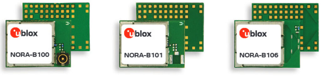
There are three Nora-B1 products, differing in their antenna set-up mainly:
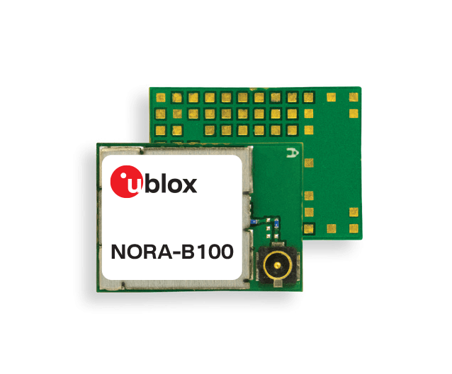
NORA-B100 with U.FL connector for an external antenna
NORA-B101 with antenna pin for an external antenna
NORA-B106 with internal PCB antenna
Promising industrial applications of these modules can be found in industrial automation, medical and healthcare, telematics, smart cities, and buildings. Specific applications may include connected tools, advanced and medical wearables, smart lighting, asset tracking, indoor location, low power sensors, as well as wireless-connected and configurable equipment.
Samples for these modules are scheduled to be available in Q4 2020. More information can be found here.
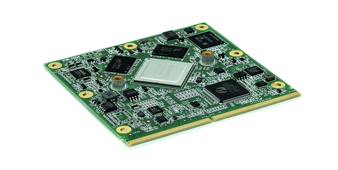
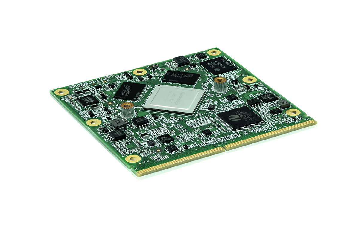
The Kontron SMARC-fA3399 module with Arm® Rockchip processor is suitable for high performance applications and is leading regarding price/performance ratio – a dedicated software community continuously pushes the application spectrum
Kontron, a global leader in IoT/Embedded Computing Technology (ECT), is launching the new fA3399 SMARC module, which uses the Rockchip RK3399K Arm® processor. In the benchmark of Arm®-based modules, the new module has the highest performance compared to its price, with six processor cores, which are derived from an energy-saving dual-core Arm® Cortex®-A72 and quad-core Cortex®-A53.
The robust module complies with the new SMARC 2.1 module standard with dimensions of 82 x 80 mm and is designed for the extended temperature range of -20 to +85 degrees Celsius. The module includes 2 GB, 4 GB or 8 GB Low-Power Double Data Rate (LPDDR4) SDRAM Memory down; displays can be connected via LVDS, DP and HDMI and an Arm® Mali-T860MP4 GPU ensures high performance for 2D and 3D graphic displays. Other connections include two Gbit Ethernet ports, three PCIe interfaces, six USB 2.0 and one USB 3.0 interface.
The Rockchip-CPU offers a perfect platform for non-critical applications around POS/POI like digital signage, retail or kiosk. Here, price pressure and speed are important drivers, because time-to-market is crucial to quickly place new contents/contexts close to the end customer.
Experiments are often based on the agile concept of the minimum viable product (MVP) and in this environment of customer communication, new possibilities of Artificial Intelligence are also used, which requires high computing power. This applies, for example, to advertising or information terminals that use AI image recognition algorithms to display adaptive content – depending on the gender and age of the recipients. Another example is supermarket scales that automatically recognize which fruit or vegetables are to be weighed.
All common Linux operating systems are supported, and since the processor is very well established in the maker environment, a large community is continuously developing the open source applications further on.
Sample quantities are available from Q1/2021. Kontron is also planning a 3.5″ board with this CPU.