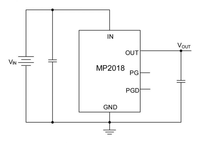
MPS’ MP2018 is a 16 V, 500 mA, low quiescent current linear regulator that features thermal shutdown and short-circuit protection (SCP)
The MP2018 from Monolithic Power Systems is a low-power, linear regulator that supplies power to systems with high-voltage batteries. This device includes a wide 3 V to 16 V input voltage range, low dropout voltage, and low quiescent supply current. The low quiescent current and low dropout voltage allow the MP2018 to operate at extremely low power levels, making it ideal for low-power microcontrollers and battery-powered equipment. The device is available in 3.3 V and 5 V fixed output voltage options. The regulator output current is limited internally and the device is protected against short-circuit, overload, and overtemperature conditions. The MP2018 also includes thermal shutdown and current-limiting fault protection and is available in a TO252-5 package.
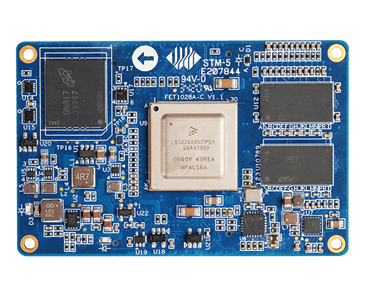
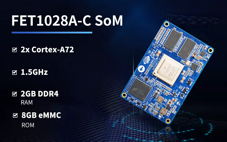
Forlinx has published details on the headless sandwich-style OK1028A-C SBC with a FET1028A-C module powered with a 1.5GHz, dual-core, Cortex-A72 LS1028A. The SBC comes with the support for the LVDS interface to enable HMI (Human-Machine Interface) applications.
The FET1028A-C module has the support for five 2.5GbE ports but the OK1028A-C SBC is limited to five 1GbE ports. The OK1028A-C is equipped with a display interface and TSN (Time-Sensitive Networking). TSN is the technique that is often used as an economic alternative to proprietary Fieldbus technologies. It provides Ethernet time synchronization for guaranteed latency and Quality of Service (QoS).
The 65 x 42mm FET1028A-C module comes with 2GB DDR4 and 8GB eMMC memory. Other features include the support for DP 1.3 and eDP 1.4 interfaces up to 4Kp60. Available I/Os are 2x USB 3.0, 2x CAN FD, 4x UART, 6x I2C, 6x I2S, 2x SPI, and SD 3.0. The module has a robust operating temperature range of -40 to 85℃.
The SoM provides a 4-port TSN switch with 2.5GbE support as well as support for a fifth 2.5GbE port and a GbE port. Five of these native GbE ports can be configured by SerDes with SATA III and 2x up to 8GT/s PCIe 3.0 in various combinations with SGMII and QSGMII Ethernet.
Overview of SoM FET1028A-C :
CPU: NXP LS1028A, Dual-core Cortex-A72 @1.5GHz
Memory: 2GB DDR4, 8GB eMMC
Interface:
1x Display Port; DP1.3 and eDP 1.4, up to 4Kp60
eSDH; SD3.0
Ethernet; CPU has 6 native MAC, up to 2.5Gbps
PCIe 3.0; up to 8GT/s, configured by SerDes
SATA 3.0; up to 6Gbps , configured by SerDes
USB 3.0; up to 5Gbps
UART; can support 1x DUART or 4x UART
OS: Ubuntu 18.04
Power input: DC 12V
Working temperature: -40℃~ +85℃
Dimensions: 42mm×65mm
Ubuntu18.04 is well supported with apt-get installation on this board. Targeted applications are in the field of industrial IoT, TSN, SD-WAN, 5G CPE, edge computing gateway, IP-PBX, smart factory, information security, intelligent transport, power management and, various other fields.
The FET1028A-C module and OK1028A-C SBC appear to be available at an undisclosed price. More information may be found on the Forlinx FET1028A-C product pages.
We have all been there. You get a new development board, you go online to check how you communicate with it and then you realize you need a new connector that costs some extra cash. And here goes on the cycle of electronic waste, because it generally only works with boards from that company, hence you can deem them, dust catchers, as they provide no other use to you. This becomes even more inconvenient when you have to work in more than one place and keep forgetting the connectors. And I did not bring up debugging, which is mandatory if you do more than a printf(“Hello World!”), and you do, so we can add a logic analyzer to the mix, it is something you should not live without. If only there was a way to condense all this clutter into a single package… Wait, there is, Tigard!
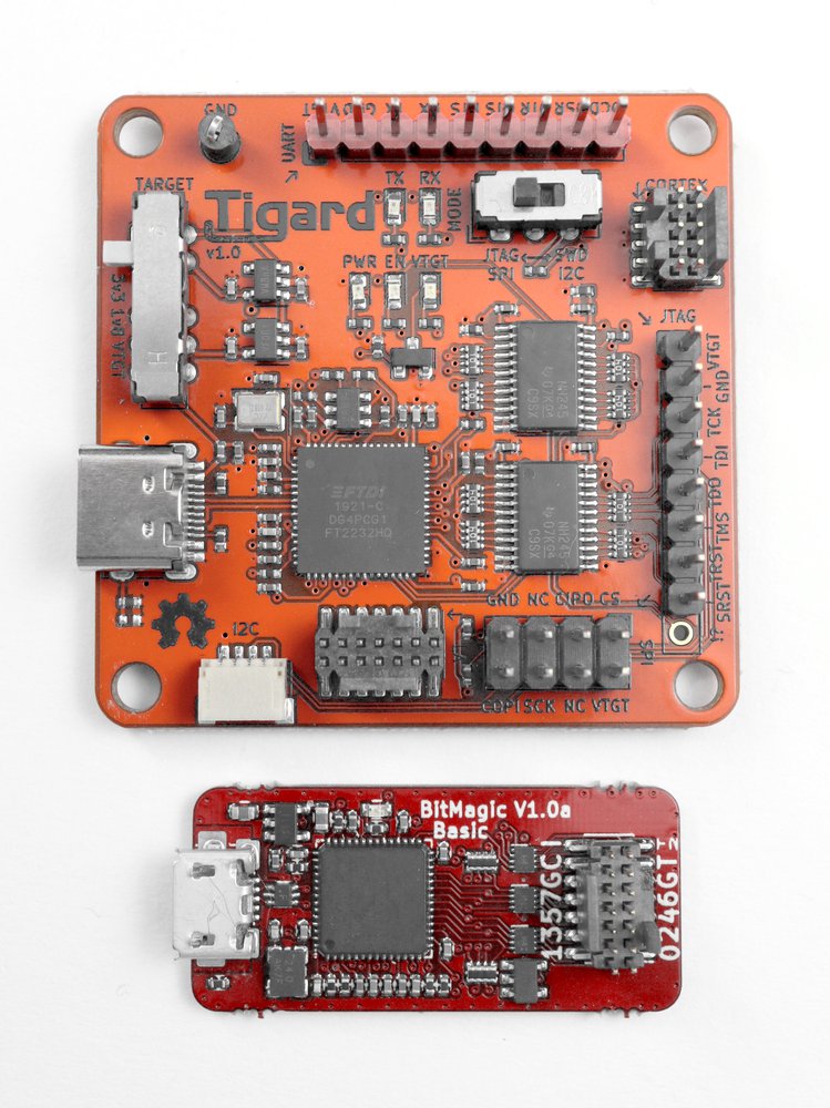
Tigard is an open-source, multi-protocol multi-voltage PCB to be used in hardware hacking. It combines a bunch of common pinouts, a labeled wiring harness, an onboard level shifting, and a connector for a logic analyzer and was specifically designed to attach and communicate with the low-speed interfaces found in hardware platforms. Tigard supports the most popular interfaces and some very useful features on a very small board. It can act as a replacement for many of your tools bought specifically for this or that board and just clutter your working space and add to your project’s expenses. It has native support for commonly used hardware tools, such as OpenOCD, FlashROM, and many more. The Tigard may be a simple device, but it enables about 80% of all the common hardware hacking tasks needed, so it can serve as a very useful starting point, or even as the only thing you need.
The TIgard along with a companion logic analyser
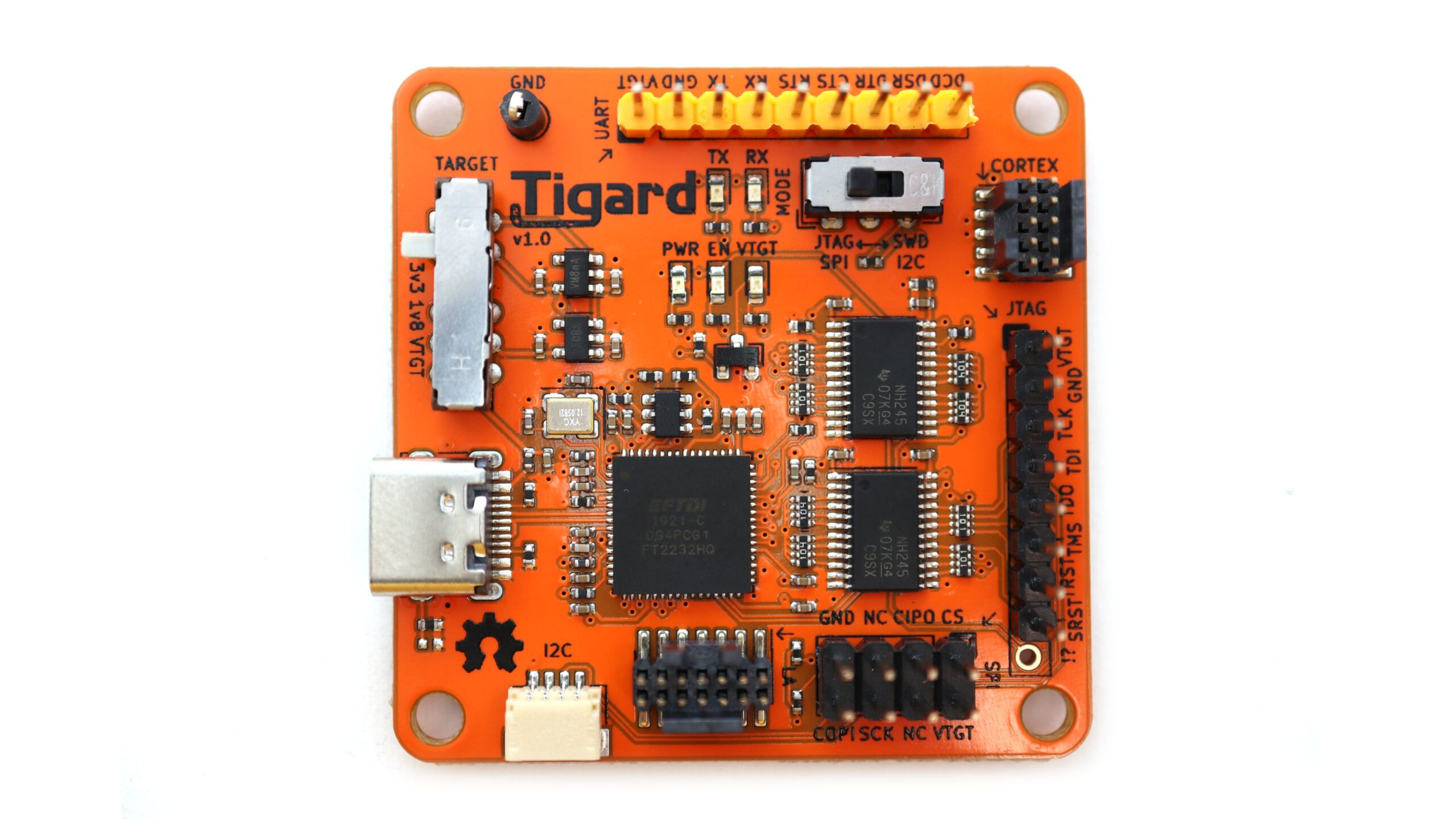
Regarding specifications, the Tigard has:
USB Type-C high-speed interface (480 Mbps)
FTDI FT2232HQ dual high-speed multipurpose UART / FIFO IC
High-performance directional level shifters ranging from 1.8 to 5.5 V
Switch to choose between on-board 1.8, 3.3 and 5 V and off-board target voltage supplies
Switch to choose between SPI / JTAG and I2C / SWD modes
Logic analyzer port to check the signals on devices
Indicator lights for debugging purposes
Now, where can you apply this? For starters, you can plug it into a device you are trying to reverse engineer, program MCUs by using the JTAG and SWD interfaces and use the logic analyzer port (and a respective logic analyzer) to observe the interactions at the same time, for instance, with an I2C OLED display.
Lastly, the Tigard is available through CrowdSupply, is already funded. You can get the Tigard for $39, the Tigard with a logic analyzer for $69, and a crazy kit for $1337. Overall, we think the second option is the most competitive.
Are you on the market for a beefy, general use or cluster computer, but do not want to break the bank or have a giant, power-hungry machine in your office? You might be thinking “nah, too many compromises, no way this is going to work”. Then think again, because you should never underestimate the power of the Raspberry Pi. Now, if you place 4 Raspberry Pi Compute Module 4 boards with the aid of a Turing Pi 2, there you have it!
The Turing Pi 2 (is of course, a second iteration) is a break in the trends of computing, due to its small size and enormous capabilities. Making use of the new Compute Module 4 from Raspberry Pi, it places up to four of them in order to provide as much or more computing power than its predecessor, which used seven Compute Modules 3+, downsizing an already small cluster! Right now, let us discuss the internals of the Turing Pi 2. Being a mini-ITX desktop cluster enables you to configure up to four Compute Module 4’s (CM4) with a maximum of 32 GB of RAM memory. Its mainboard includes connectors for Mini PCI Express, two SATA 3 ports, dual Gigabit Ethernet, an ATX power connector, HDMI output, and a DSI to which you can connect the official Raspberry Pi touchscreen, besides four USB ports (there is no confirmation that they are USB 3.0, but it is likely).
There is something you might be wondering if you own a Compute Module 4: they are not compatible with the Mini PCI Express, so how did they solve this issue? Simple, they designed an adaptor specifically for the CM4. They also considered the cooling issue we have been witnessing with the new Raspberry Pi modules. As they run hotter than hell (especially when we overclock them), a fan is necessary to cool each of the CM4 modules individually. A nice touch that will only increase the performance and the lifespan of your cluster.
The layout of the Turing Pi 2
Now, where can you use the Turing Pi 2? Firstly, as an edge infrastructure for your applications (both consumer and industrial grade), enabling you to host your apps locally affordably and gradually adding cluster blocks if you deem necessary, along the line. Another possibility is to use it as an ARM workstation and take advantage of its 32 GB of RAM, where one node can be used to run a desktop version of an OS and the other 3 can perform compilation, testing, debugging tasks, and developing cloud-native solutions for ARM clusters.
Lastly, the pricing is not yet available, which is normal, since the product is only queued for the next year. So far, we know that is expected to be cheaper to manufacture than its predecessor and the buyers of the Turing Pi 1 will get a sweet 25% discount. We can only wait patiently for more updates on the promising 2!
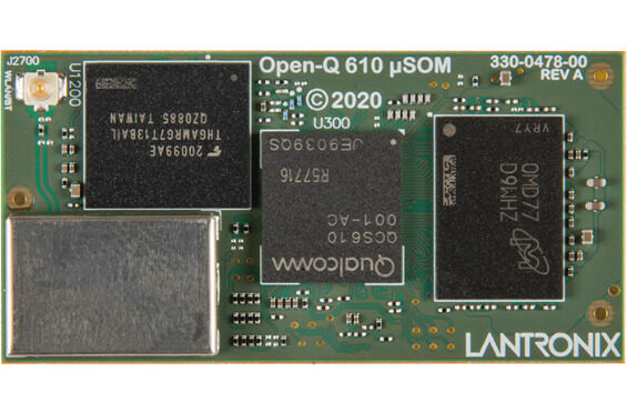
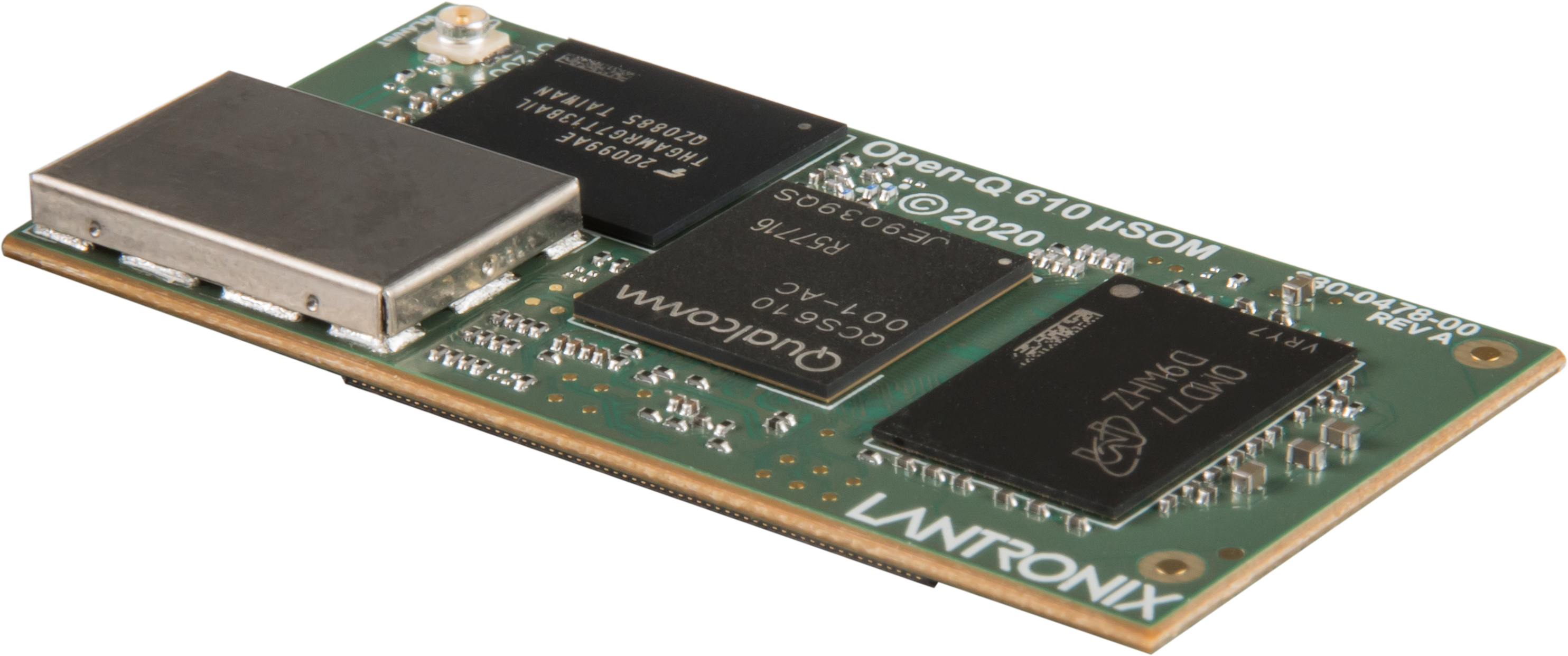
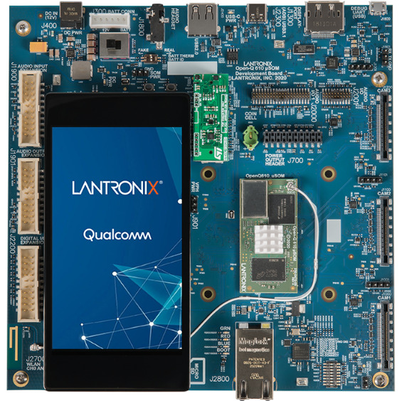
Lantronix had announced its new Lantronix Open-Q™ 610 μSOM based on the powerful Qualcomm® QCS610 System on Chip (SOC). This micro System on Module (µSOM) is designed for connected visual intelligence applications with high-resolution camera capabilities, on-device artificial intelligence (AI) processing and native Ethernet interface. They also released a Qualcomm camera-focused development kit that run linux and an AI enabled octa-core Qcs610 Soc with triple 4-lane MIPI-CSI interfaces priced At $995 with shipments due in November. About the Open-Q 610 μSOM Paul Pickle, CEO of Lantronix says:
“Our long and successful relationship with Qualcomm Technologies enables us to deliver powerful micro SOM solutions that can accelerate IoT design and implementation, empowering innovators to create IoT applications that go beyond hardware and enable their wildest dreams”
Lantronix’s Open-Q™ 610 μSOM is an ultra-compact (50mm x 25mm) production-ready SOM based on the powerful QCS610 SoC, with built-in Neural Processing Engine for on-device edge AI capabilities. Aimed at connected visual intelligence applications, with advanced built-in image sensor processing such as staggered HDR, lens de-warp, dual camera stitching, and image de-fog, the 610 μSOM is the ideal platform for your next smart camera product. Available with a full-featured development kit for ease of evaluation and POC development, the platform is supported by a Yocto Linux SDK with Qualcomm optimizations, GStreamer audio/video framework, and AI support for TensorFlow Lite and Qualcomm SNPE.
The Open-Q 610 µSOM provides the core computing capabilities for:
Image processing
Artificial intelligence
Advanced audio processing
Low power sensor processing
The new Lantronix Open-Q 610 μSOM is based on the powerful Qualcomm QCS610 SOC, the latest in the Qualcomm® Vision Intelligence Platform lineup targeting smart cameras with edge computing. Delivering up to 50 percent improved AI performance than the previous generation as well as image signal processing and sensor processing capabilities, it is designed to bring smart camera technology, including powerful artificial intelligence and machine learning features formerly only available to high-end devices, into mid-tier camera segments, including smart cities, commercial and enterprise, homes and vehicles.
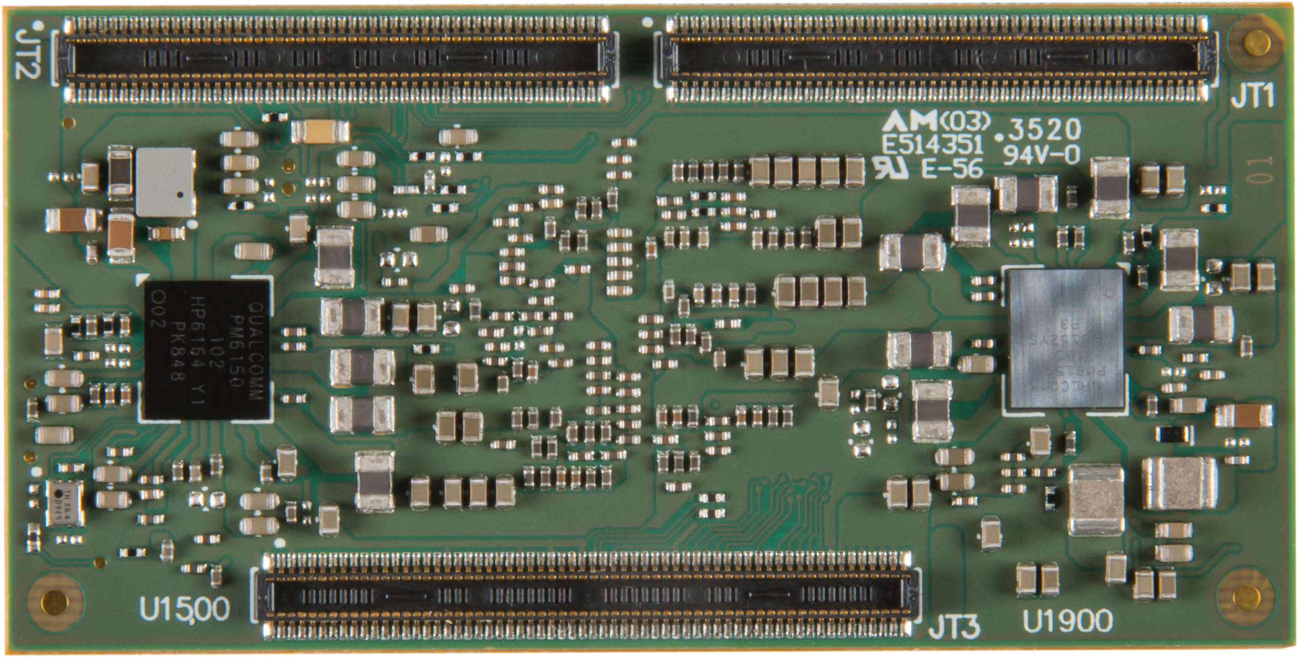
The Open-Q 610 μSOM follows other 50 x 25mm Intrinsyc μSOM modules such as Snapdragon 845 based Open-Q 845 uSOM. The Open-Q 610 μSOM ships with 2GB LPDDR4x and 16GB eMMC. The module integrates a native GbE controller and a Qualcomm WCN3980 module with dual-band 802.11a/b/g/n/ac and Bluetooth 5.x. Media interfaces include 3x 4-lane MIPI-CSI, 4-lane MIPI-DSI, DP 1.4 with Type-C support, and SLIMBus, SoundWire, and MI2S audio. Other I/O includes USB 3.1 and 2.0 plus SD, UART, I2C, SPI, and GPIOs. The 3.7V module is equipped with a PMIC.
Open-Q 610 Development Kit
The companion Open-Q 610 Development Kit is a full-featured platform with available software tools, documentation, and optional accessories. It delivers everything required to immediately begin evaluation and initial product development. The development kit integrates the production-ready Open‐Q 610 µSOM with a carrier board, providing numerous expansion and connectivity options to support the development and testing of peripherals and applications. The development kit, along with the available documentation, also provides a proven reference design for custom carrier boards, providing a low-risk fast track to market for new products. The Open-Q 610 μSOM Development Kit is equipped with a single GbE, USB 3.1 Type-C, USB 2.0 host, and micro-USB serial debug ports. Available also is a dedicated DP 1.4 port that can be deactivated when running the Linux SDK.
There is no price available for the open-Q 610 μSOM. However, the Open-Q 610 μSOM Development Kit is available for pre-order at $995, with shipments due in November. More information about specification and documentation can be found on the Lantronix announcement, Open-Q 610 μSOM and Open-Q 610 μSOM Development Kit product pages, with the latter showing a shopping link.
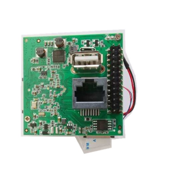
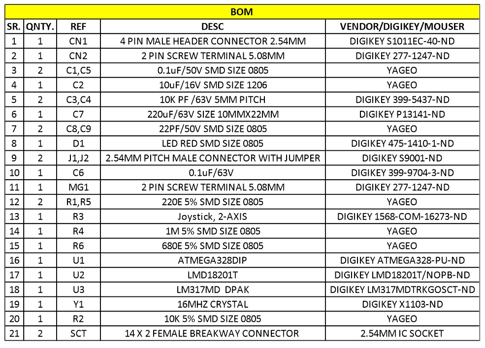
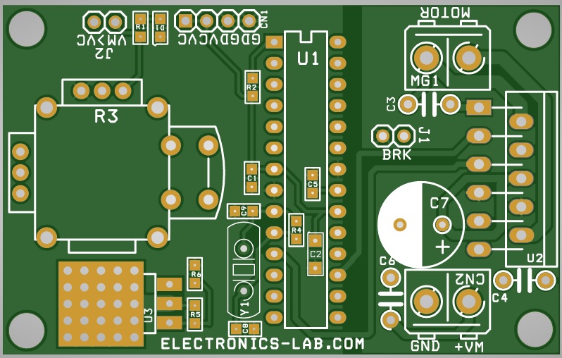
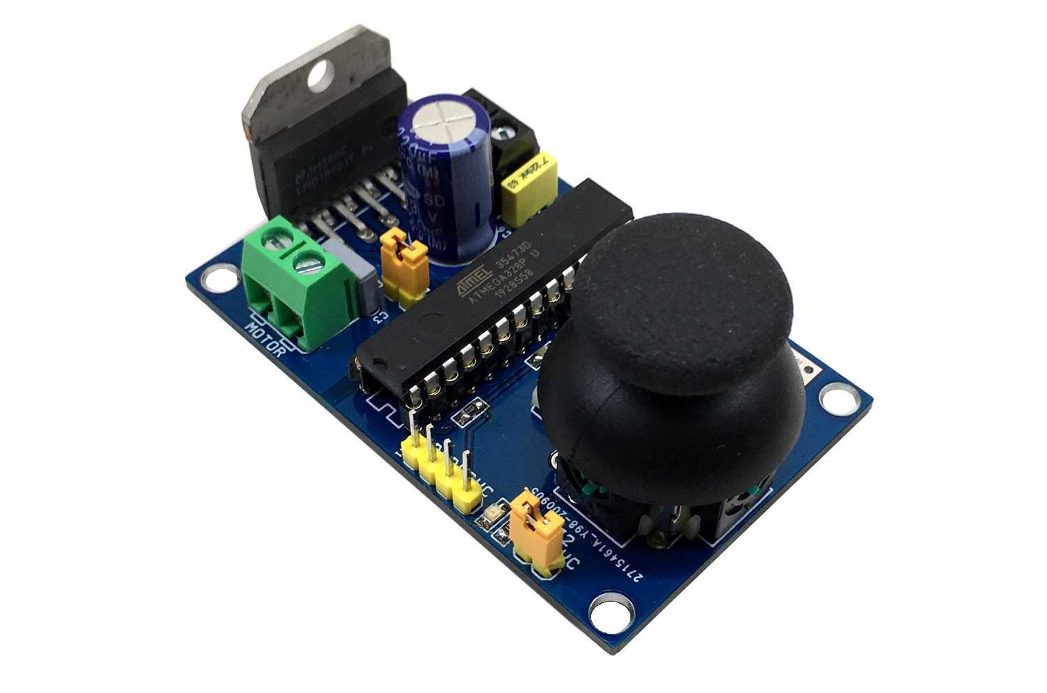
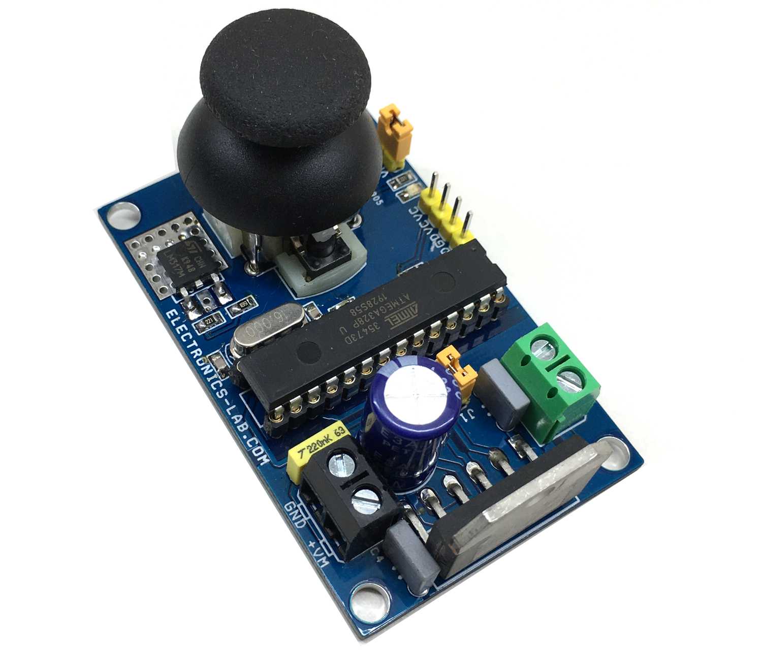
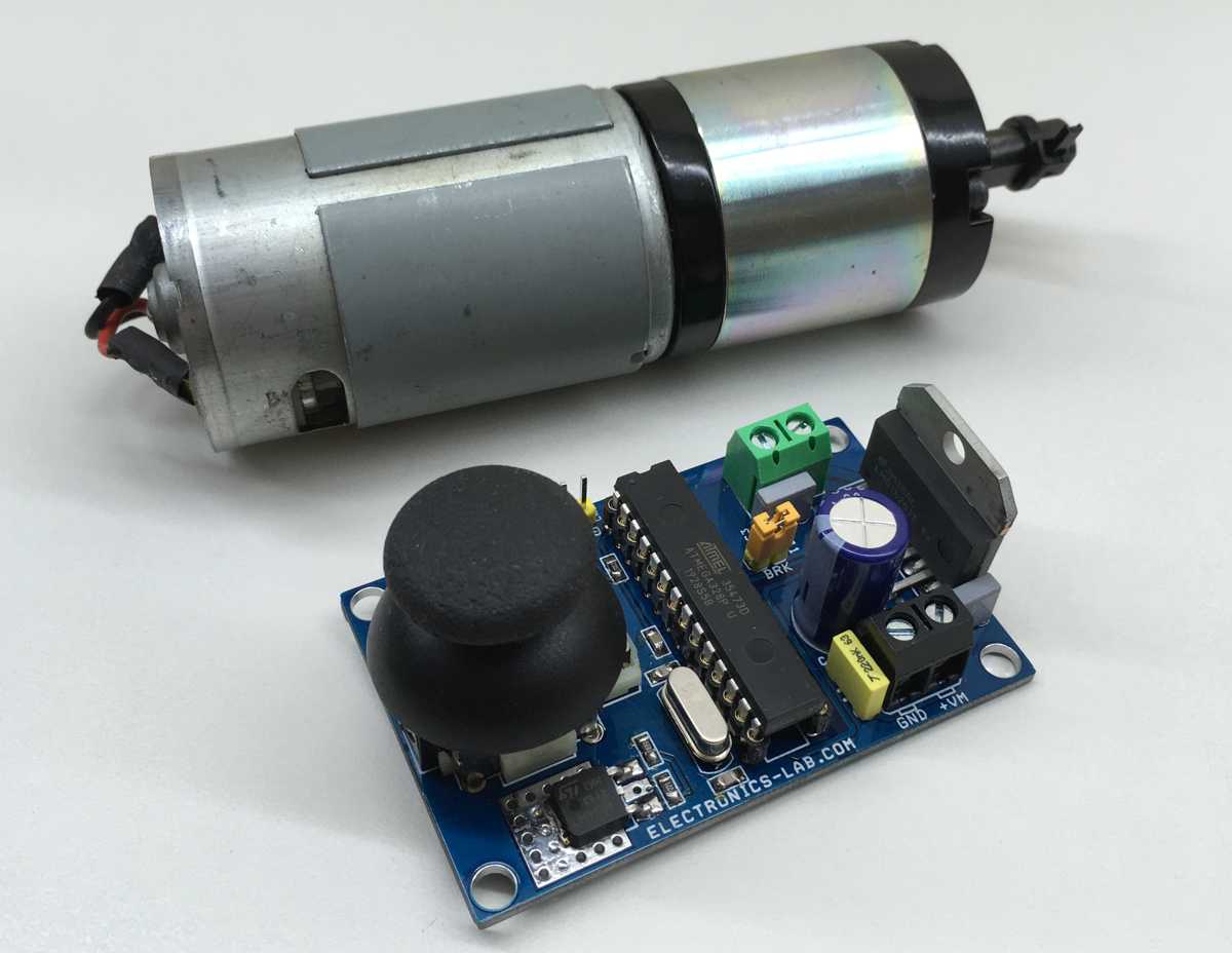
This DC Motor controller provides direction and speed control of a brushed DC motor using a Joystick. This is an Arduino compatible open-source hardware with various applications. It can be used to control scissor lift motor, Linear actuator, Camera slider, camera pan-tilt head, curtain motor, power window motor, robotics, smart furniture automation, hospital furniture automation, projector up/down controller, TV up/down controller are few application examples. The board provides superb performance, smooth movement of motor, and hassle-free use. You only need to connect the motor wires, power the board, and you ready to go.
The controller has 3 main elements, Atmega328 Micro-Controller, LMD18201 DC Motor H-bridge, and Joystick connected to A0 Analog pin of microcontroller. This board can control DC motor up to 48V DC with continuous current up to 3A and peak current 6A.
Brushed DC Motor Speed and Direction Controller Using Joystick – [Link]
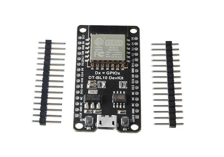
DT-BL10 is a development board powered by BL602 WiSoC that sells for around $5. This board is specifically designed to work with a 32-bit RISC-V CPU with dynamic frequency from 1MHz to 192MHz. It has a 276KB SRAM and 128KB ROM.
The main focus of this board is on its wide range of wireless support. It has the support for Wi-Fi 4 802.11 b/g/n and Bluetooth 5.0 Low Energy. Wi-Fi security standards WPS/WEP/WPA/WPA2/WPA3 are available also with this low-power IoT application-focused board.
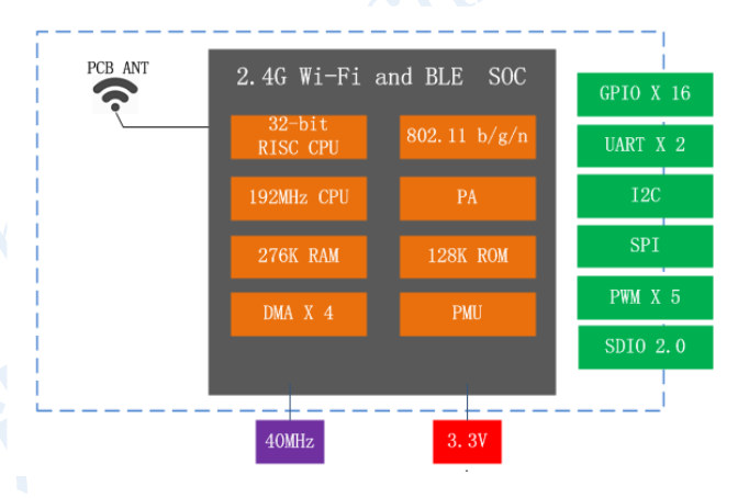
DT-BL10 Block Diagram
Moreover, a variety of security features such as secure boot, secure debug, XIP QSPI On-The-Fly AES Decryption (OTFAD), AES-128/192/256 are supported on this 49 × 26 × 3 mm board. Peripheral interfaces include SDIO, SPI, UART, I2C, IR remote, PWM, ADC, DAC, ACOMP, PIR, etc. Flexible GPIO configurations are supported. BL602 has a total of 16 GPIOs.
Board Specifications for the DT-BL10 :
SoC : Bouffalo BL602 RISC-V processor @ up to 192 Mhz with 276KB RAM, 128KB ROM with WiFi and Bluetooth
Wireless :
2.4GHz 802.11b/g/n WiFI 4 up to 65 Mbps (802.11n) or 26 Mbps (802.11g)
Power consumption : Deep-sleep mode: 22mA; deep standby mode: 2mA
Dimensions : 20 x 16 x 3mm
Temperature Range : -20°C to +85°C
Targeted toward the well-established low-power IoT applications, this board tries to rival the ESP8266 and ESP32 solutions which are already very affordable and community-supported. It may take the heat off from this competition with the implementation of the BL602 SoC. Time will tell if it can make an impact in the maker community. More information can be found on this product page.
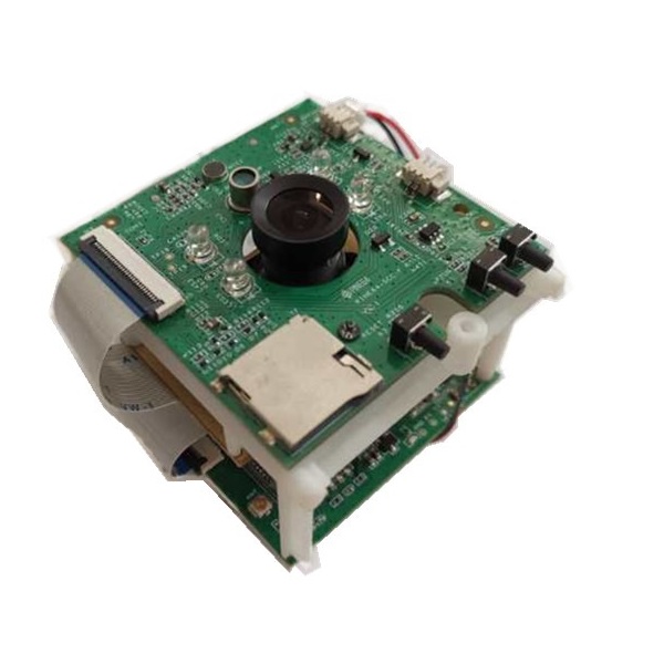
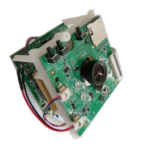
Pine64 announced its open-spec PineCube back in 2019 as a device called The Cube equipped with the 8-megapixel Sony iMX179 CMOS sensor. But for the technical issues with the Sony sensor, they changed it into a 5MP OmniVision OV5640 sensor and implemented the new name PineCube. The camera development kit has now shipped for $29.99.
The PineCube is powered by the SoC Cortex-A7 based Allwinner (Sochip) S3 clocked at 800MHz. This camera-application minded SoC allows 1080P@60fps decode and encode with support for up to two HD cameras. The OmniVision OV5640 is a 1/4 inch CMOS sensor that captures 2592 X 1944 @ 15fps and 1920 X 1080 @ 30fps video. It has an electronic rolling shutter with autofocus support for objects at 10cm-to-infinity distance. It comes with an adjustable control over brightness, contrast, color saturation, hue, gamma, white balance, and exposure. It has a FOV of 65-degree.
The PineCube
There is only a single RAM option of 128MB DDR3 and 26 pin GPIO for this 55 x 51.5 x 51mm 55gram board. Other features incorporate fast ethernet with passive PoE, 2.4GHz WiFi, micro-USB power, and USB 2.0 host ports, mic and speaker, and a bootable microSD slot. A battery pack and a 4.5-inch display are optional. The PineCube also offers an M12-compatible attachment. A variety of lens attachments are available for the kit.
PineCube Specification Summary :
Processor: Allwinner S3 (1x Cortex-A7 @ 800MHz)
Memory/storage:
128MB DDR3
128Mb SPI NOR flash
MicroSD slot (bootable)
Networking:
10/100Mbps Ethernet port with passive PoE
2.4GHz 802.11n/g/b
Sensor:
OmniVision OV5640 camera sensor — 5MP with M12 attachment for optional lenses
IR LED array for night vision
Photoresistor sensor
Mic, speakers, volume button
Optional 4.5-inch RGB LCD screen
Other I/O:
USB 2.0 host port
Micro-USB port for PD
26-pin GPIO
Power: 5V/1A via micro-USB or 4-18V via PoE; optional 950-1600mAh Lithium Polymer Ion Battery Pack (model 903048)
Operating System: Linux SDK; supports NixOS, stock Linux
More information: The PineCube is available now for $29.99 on Pine64’s shopping and wiki pages.
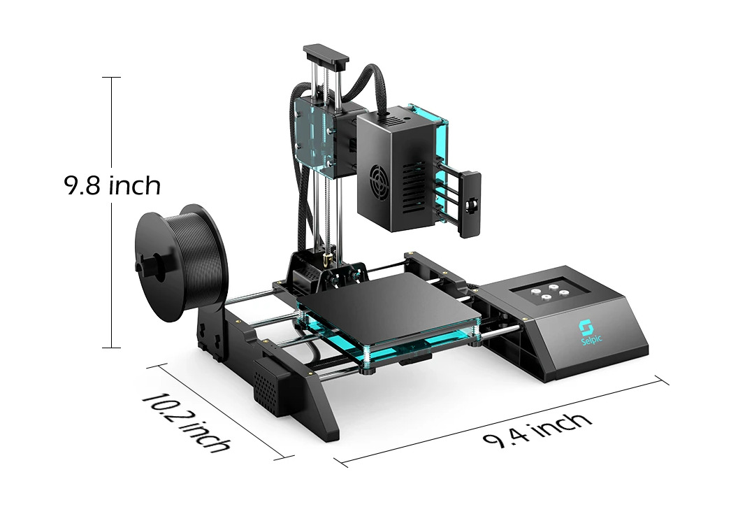
Selpic Inc, a leading company focusing on digital printing solutions, has been developing innovative printing technologies since its foundation. Following the debut of Selpic P1, Selpic is going to launch the world’s most cost-effective 3D printer Star A on Kickstarter soon.
Star A is an ultra-compact and lightweight open-source 3D printer which is also easy to operate and set up. Most importantly, it supports extended functions, providing more possibilities of 3D printing.
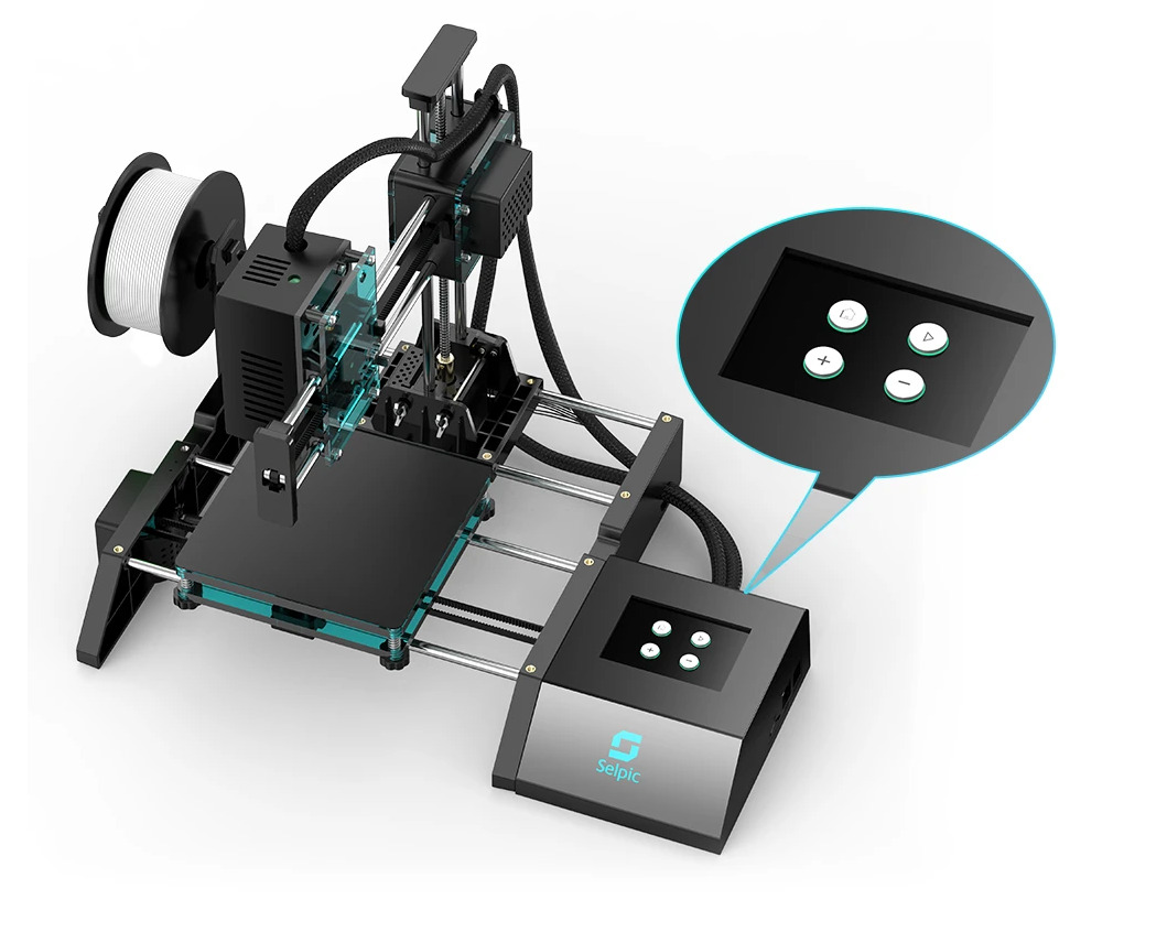
Weighing 4.4 Ibs and measuring 10.29.49.8 inch, Star A is 3 times lighter than ordinary printers. With its compact body, Star A saves space and can be moved easily. Also, Star A is easy to assemble and set up. Its assembly can be finished within 4 steps. What you need to do is just turning screws, connecting 2 cables and setting filaments ready. Besides, 4 intuitive operating buttons can help with an easy reset, printing, filament feed and release.
With the X-axis and Y-axis accuracy of 100 μm and the Z-axis accuracy of 50 μm, Star A’s printing resolution is ±0.1 mm and its layer thickness can achieve 0.1~0.2 mm. Adopting low-noise motor, Star A keeps its working noise below 60 dB, which greatly improves the users’ experience. Besides, Star A has a resume-printing function. In the cases of an unexpected power outage or filament exhaustion, this function helps save filaments and improves printing efficiency.
It is worth mentioning that Star A is an open-source 3D printer. You can adjust the product parameters by modifying its code. We provide add-ons. By upgrading Star A’s parts, you can get the higher hotbed temperature up to 100 ℃ and 2.4 inch full-color and highly-sensitive touch screen. And with the laser head installed, you may have the laser engraving on the leather, cardboard, wood, etc.
Besides what is mentioned above, Star A has more surprises for you to explore. Should you be interested, Star A will meet you guys on Kiskstarter with only $99 pretty soon. Sign up now to enjoy the super early bird discount (50% off the $199 MSRP) for the first 100 backers only.
Click the following link to participate in our giveaway activity and grab the chance of winning 3 units of Star A 3D printer: https://gleam.io/2Baaw/selpic-star-a
UPDATE 3/11/2020: Selpic Star A 3D printer will be launched on kickstarer.com at 6:00AM, Nov. 3, 2020, Pacific Time.
This DC Motor controller provides direction and speed control of a brushed DC motor using a Joystick. This is an Arduino compatible open-source hardware with various applications. It can be used to control scissor lift motor, Linear actuator, Camera slider, camera pan-tilt head, curtain motor, power window motor, robotics, smart furniture automation, hospital furniture automation, projector up/down controller, TV up/down controller are few application examples. The board provides superb performance, smooth movement of motor, and hassle-free use. You only need to connect the motor wires, power the board, and you ready to go.
The controller has 3 main elements, Atmega328 Micro-Controller, LMD18201 DC Motor H-bridge, and Joystick connected to A0 Analog pin of microcontroller. This board can control DC motor up to 48V DC with continuous current up to 3A and peak current 6A.
Arduino Code
It is an Arduino compatible hardware and a new Atmega328 chip requires the burning of Bootloader to upload the Arduino code. Follow the below link for more info on programming and boot-loader burning.
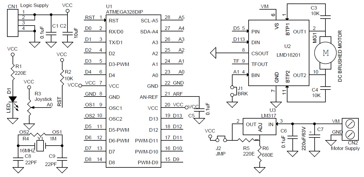
The example code drives the DC motor with a joystick. I have used only 2 pins of LMD18201 chip, PWM, and Direction pin, I have not used the break pin, close the J1 jumper to free the break option of LMD182001. Open the jumper J1 in some applications if the user wants to use the Break option.
Click the download link at the end of the article to download the Arduino example code and test this hardware.
Arduino Pins Vs LMD18201 Motor Driver Pins
Arduino Digital D5>>PWM Pin LMD18201, Arduino Digital Pin D11 >> Direction Pin LMD18201, Analog Pin A1 >> Break Pin LMD18201, Analog pin A0 >> One Axis-Joystick
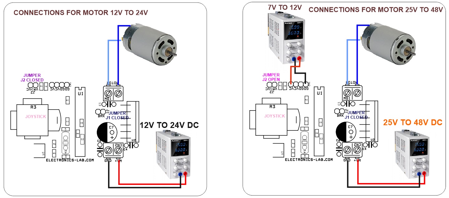
Power Supply
To run a 12V to 24V motor, the board requires a single power supply of 12V to 24V DC. To use this option Close the jumper 2 and power the CN2 wih 12V to 24V. To drive a Higher voltage motor, the circuit requires 2 separate power supplies, one for logic and one motor, in this case open the J2 jumper, use CN2 to apply motor supply 25V to 48V and CN1 7V to 24V logic supply.
Heat-sink
If you want to fetch full power from LMD18201 IC it is advisable to use a large size heatsink on the IC.
Features
Operating Power Supply 12V to 24V DC (for Motor 25V to 48V Power Refer to Note)
D1 Power LED
Joystick: Motor Direction CW/CCW and Speed Control
PWM Duty Cycle Adjustable 0 to 100% (Frequency 975Hz)
On Board Regulator L317 to Power 5V DC to Atmega328 Chip
LMD18201
The LMD18201 is a 3A H-Bridge designed for motion control applications. The device is built using a multi-technology process which combines bipolar and CMOS control circuitry with DMOS power devices on the same monolithic structure. The H-Bridge configuration is ideal for driving DC and stepper motors. The LMD18201 accommodates peak output currents up to 6A. Current sensing can be achieved via a small sense resistor connected in series with the power ground lead. For current sensing without disturbing the path of current to the load, the LMD18200 is recommended.

 The 65 x 42mm FET1028A-C module comes with 2GB DDR4 and 8GB eMMC memory. Other features include the support for DP 1.3 and eDP 1.4 interfaces up to 4Kp60. Available I/Os are 2x USB 3.0, 2x CAN FD, 4x UART, 6x I2C, 6x I2S, 2x SPI, and SD 3.0. The module has a robust operating temperature range of -40 to 85℃.
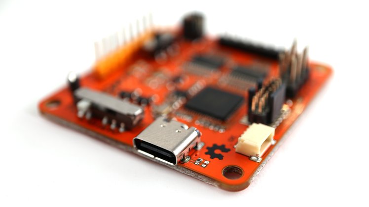

 Pine64 announced its open-spec PineCube back in 2019 as a device called The Cube equipped with the 8-megapixel Sony iMX179 CMOS sensor. But for the technical issues with the Sony sensor, they changed it into a 5MP OmniVision OV5640 sensor and implemented the new name PineCube. The camera development kit has now shipped for $29.99.