Introduction
Users of a microscope always want one with big viewing screen, and excellent image quality. One microscope that falls into this category and we had the chance to review, is the Andonstar ADSM302. ADSM302 is a multifunctional digital microscope individually designed, developed with full HD sesnor, high object distance, multi-output at the same time.
Additional the Andonstar measuring software can be used in many industries, such as industrial overhaul and teaching demonstration. Its appearance and design combines ergonomic consideration, and provides users with better experience. The ADSM302 is manufactured by Shenzhen Andonstar Technology Co and comprises an excellent quality microscope. Let’s dive in.
Unboxing
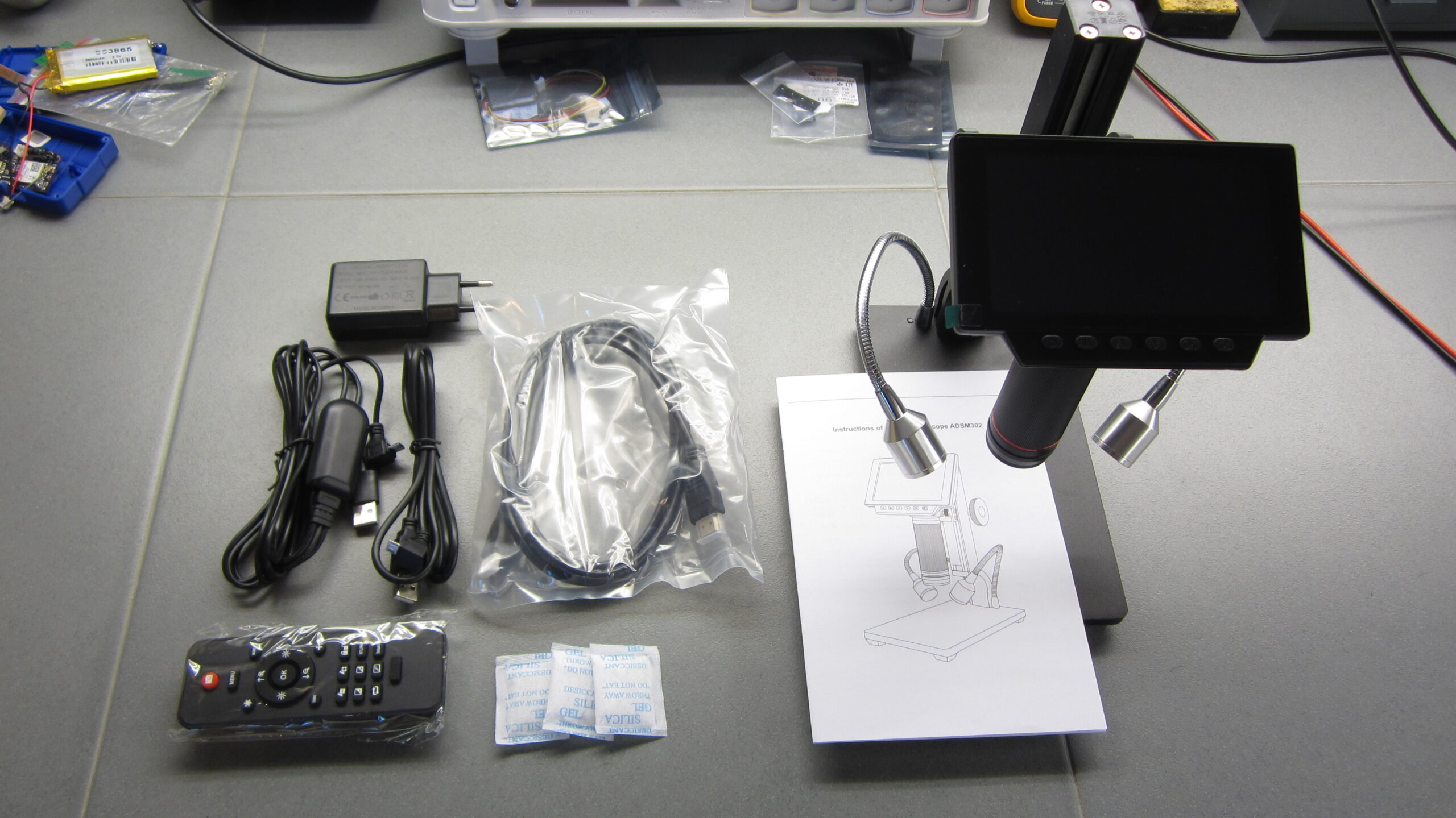
The microscope comes in a big box with plenty of insulation to protect it during transport. The box includes:
- 1 * Andonstar ADSM302 High Object Distance Digital USB Microscope
- 1 * Power adaptor
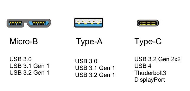
- 1 * USB cable
- 1 * HDMI Cable
- 1 * IR remote controller
- 1 * Manual (English)
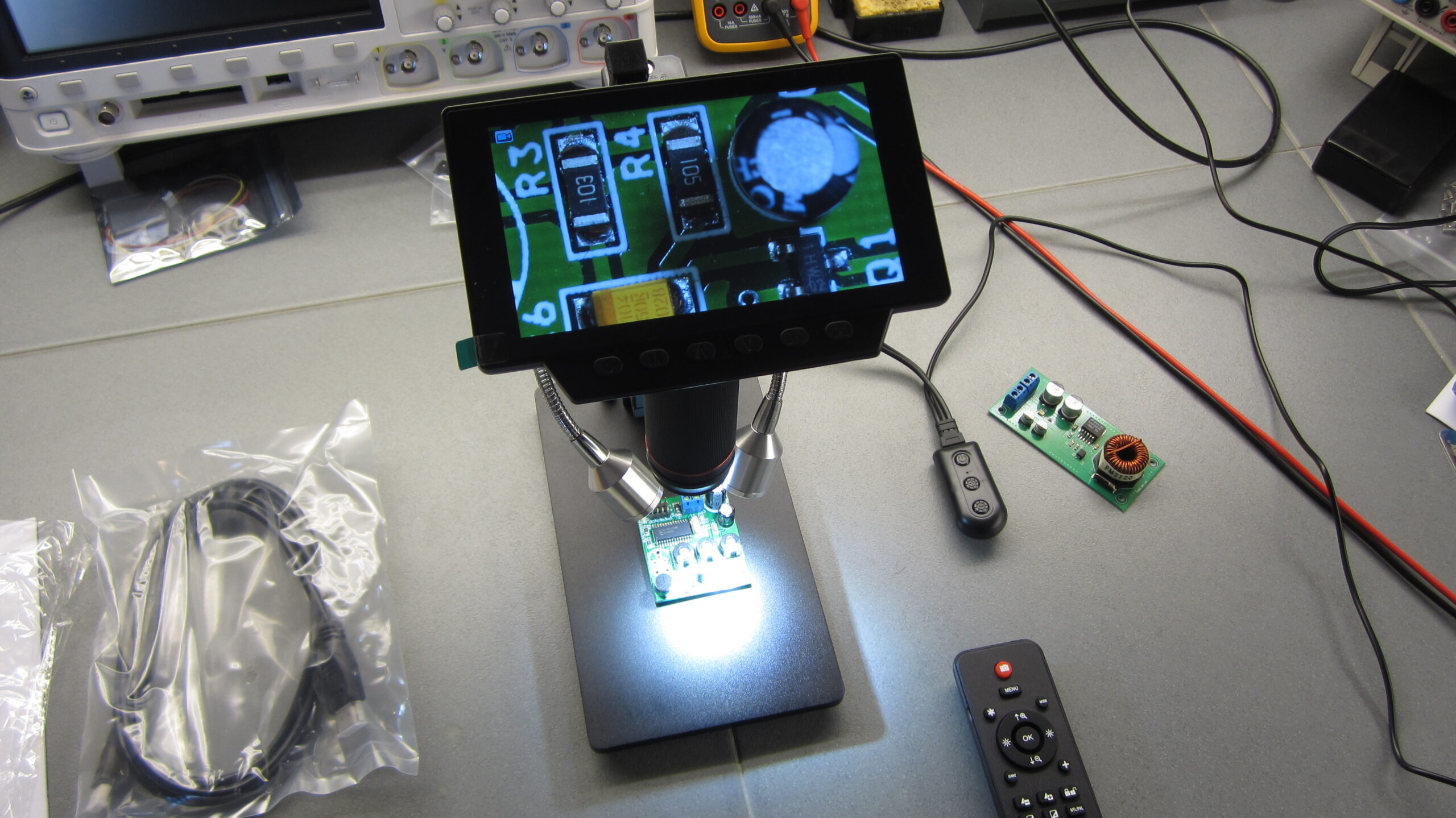
Unboxing and powering up the unit took only 4-5 minutes. The microscope comes assembled and all you have to do to start is to add batteries to the remote control and connect the light and power control cable the the USB adapter. Hit power ON button and you are ready to go.
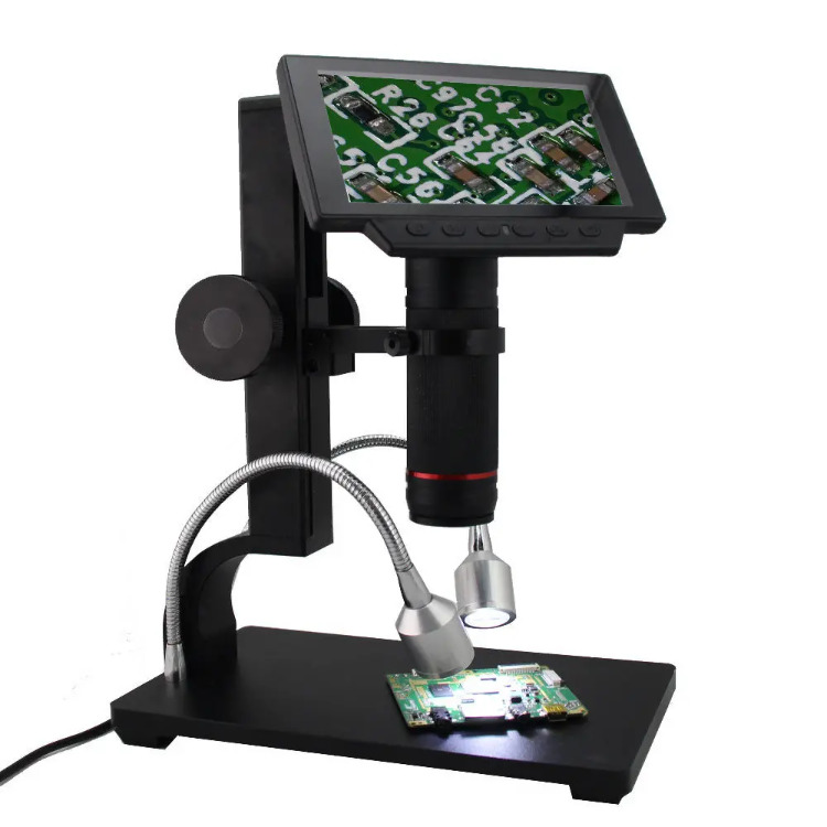
The first impression we had is that it is a well build and quality constructed microscope with precise movement of the focus and distance set knobs. The two LEDs add adequate light on the test bench and they are easily configured in both placement and light intensity.
First Impressions
The ADSM302 is the newer model of the ADSM201, with some improvements on some of the gripes people had with the older model. One area of improvement is the camera sensor. The sensor is larger and the working distance has been increased significantly because of the elongated tube for the lens to move. The ADSM302 also features a larger and higher quality screen than the ADSM201, with the ability to adjust it’s angle.
Another area of improvement is the base, which is much larger and heavier than the previous model. This give the device more stability. The objective table is big enough to do most of the soldering and repair work. One area of improvement i like is the black color, which is different from the reflective silver of the older model. This is a significant improvement, because the silver color made it hard to look at single components without glare. The Andonstar microscope is fully functional even without using it’s software or connection to a PC or TV screen.
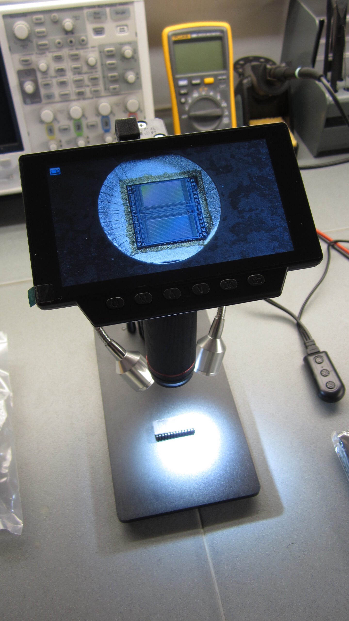
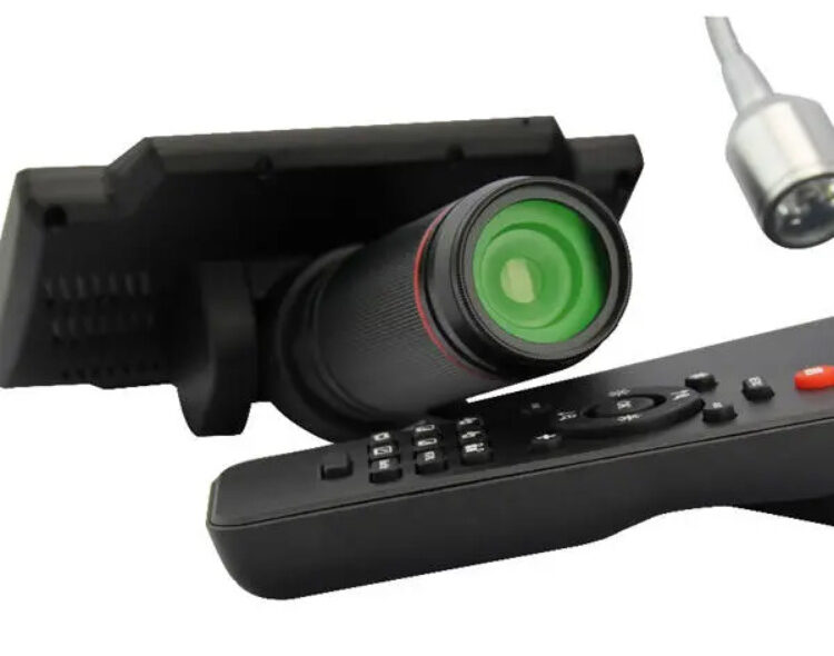
The ADSM302 features a 5-inch display. This increased resolution and size makes user experience better, from video recording to photo shooting to image analysis, making everything clearer. It also features a technical grade lens, which functions by focusing the light onto the field of view when the background is dark.
If there is too much light, the lens will deflect the light away from the light source in order to get a better image. It also features an adjustable monitor which enables the user choose the most comfortable and suitable angle from the display. Its UV filter helps to protect the lens from the heat, smoke, dust and other things which are produced by heat machines and soldering irons during repair work.
The UV filter can also help to reduce the effects of ultraviolet rays and increase the sharpness and color of the image.
Features
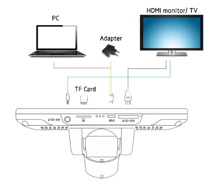
The ADSM302 can support 4 different outputs, not including its own monitor: AV-OUT, USB, HD-OUT and SD memory card. It also features buttons & IR remote, which is handy when a user is doing some repair work on the table, it would be convenient for them to capture photos, record videos, zoom in and out etc from a distance.
If you want to perform object or specimen manipulation under the viewing lens barrel, you have a maximum working distance of slightly more than 4.5 inch. This should be sufficient space to perform any sort of SMD related works. The ADSM302 features two adjustable LED illumination arms shining down both sides of your viewing object or specimen. This gives the user a very clear and concise viewing experience.
If you need to carry measurement (spacing in between circuit board holes), or tool for counting bacteria inside a petri dish, there is a calibration software made available that comes with ADSM302, and can help you with on-screen measurements.
Software
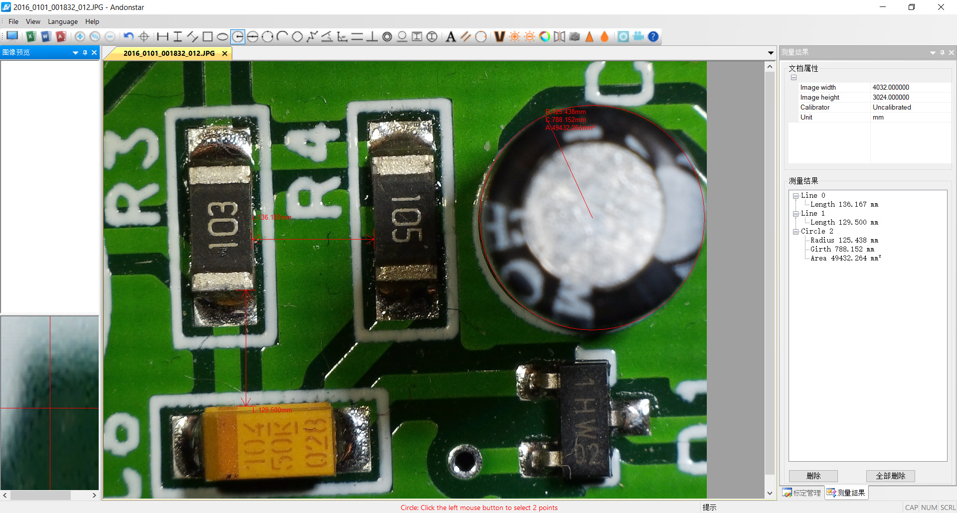
Software comes in Chinese and English and you have to go to the Language menu to change it (the third menu item from left). It offers some basic functionality to mark and measure points on an image acquired with the microscope. Before you make any measurements it is advisable to run a calibration of the software so you get some proper values.
We couldn’t find the download on the official website so we downloaded from Elektor reference page and we also included the download link below.
Specifications:
- Material: metal+plastic
- Main color: black
- Image sensor: 3 mega pixels HD sensor
- Video output: 1080P full HD;720P
- Video format: MOV
- Magnification ratio: up to 560x
- Photo resolution: 12M
- Photo format: JPEG
- Focus range: 50mm to 220mm
- Frame rate: max 30f/s under 600 lus brightness
- Storage: micro-SD card
- PC support: yes, for Windows XP/7/8/10
- Remote control battery: 2 * AAA battery (not included)
- Light source: LED light
- Power source: 5V/2A
- Rated voltage: AC 110-240V
- Stand size: 265 * 200 * 120mm / 10.4 * 7.9 * 4.7in
- Screen size: 5 inch
- Package size: 300 * 240 * 177mm / 11.8 * 9.4 * 7.0in
- Package weight: 2100g / 4.6lb
Note: The color of the plug is random.
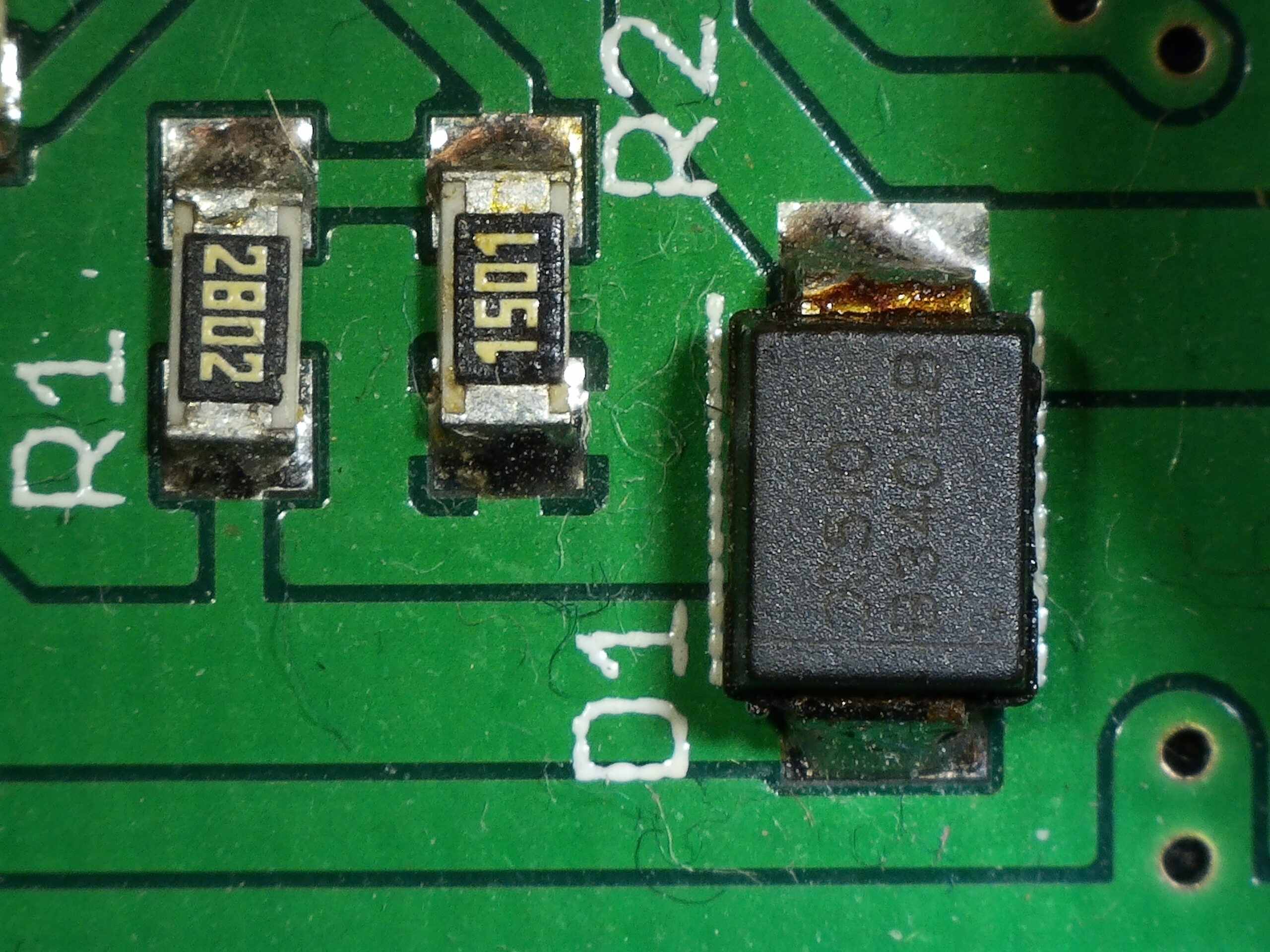
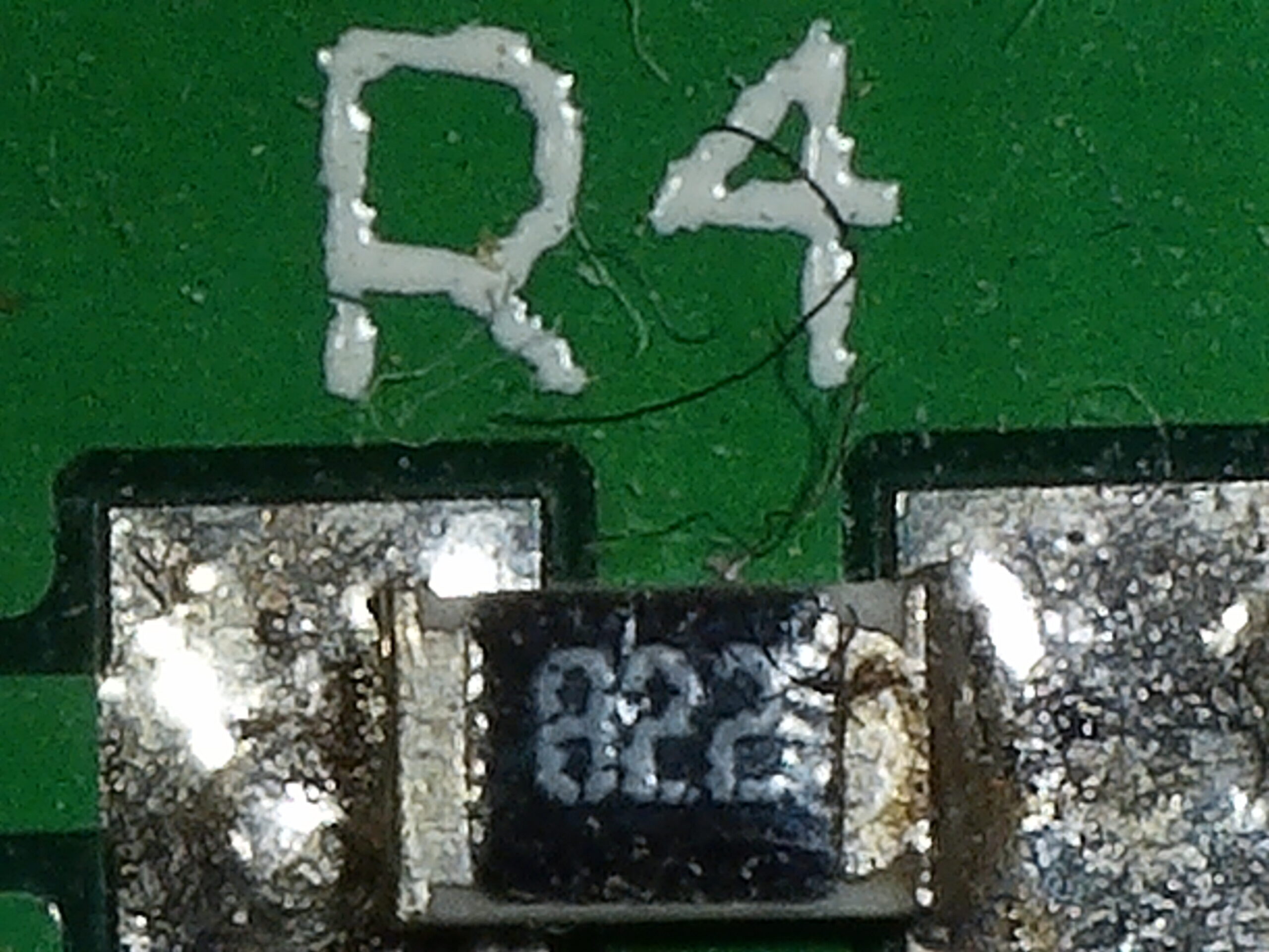
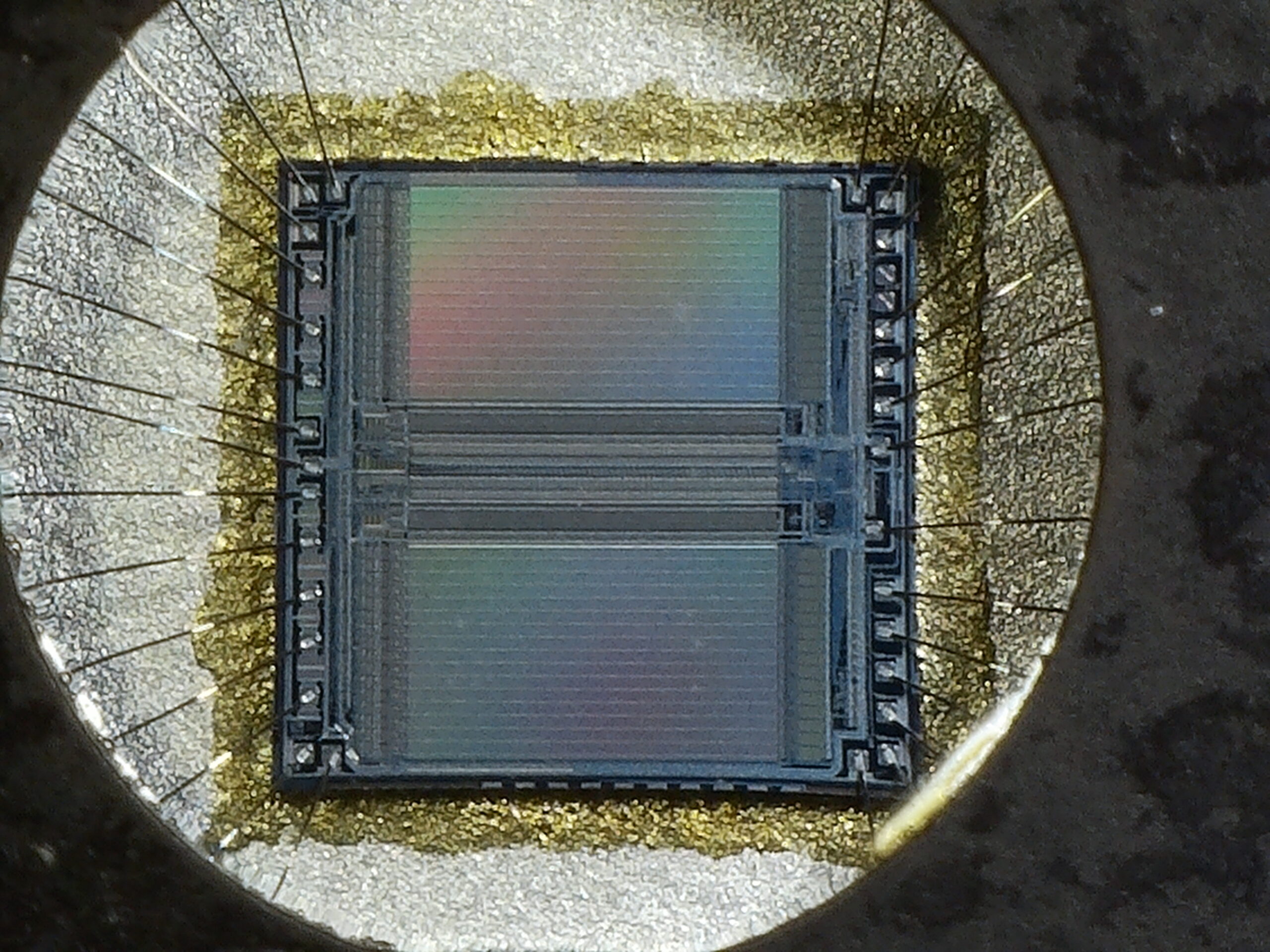
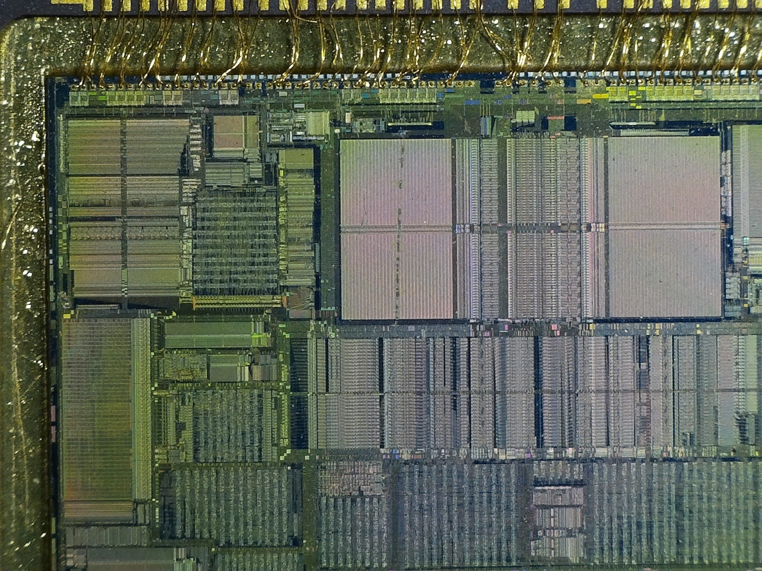
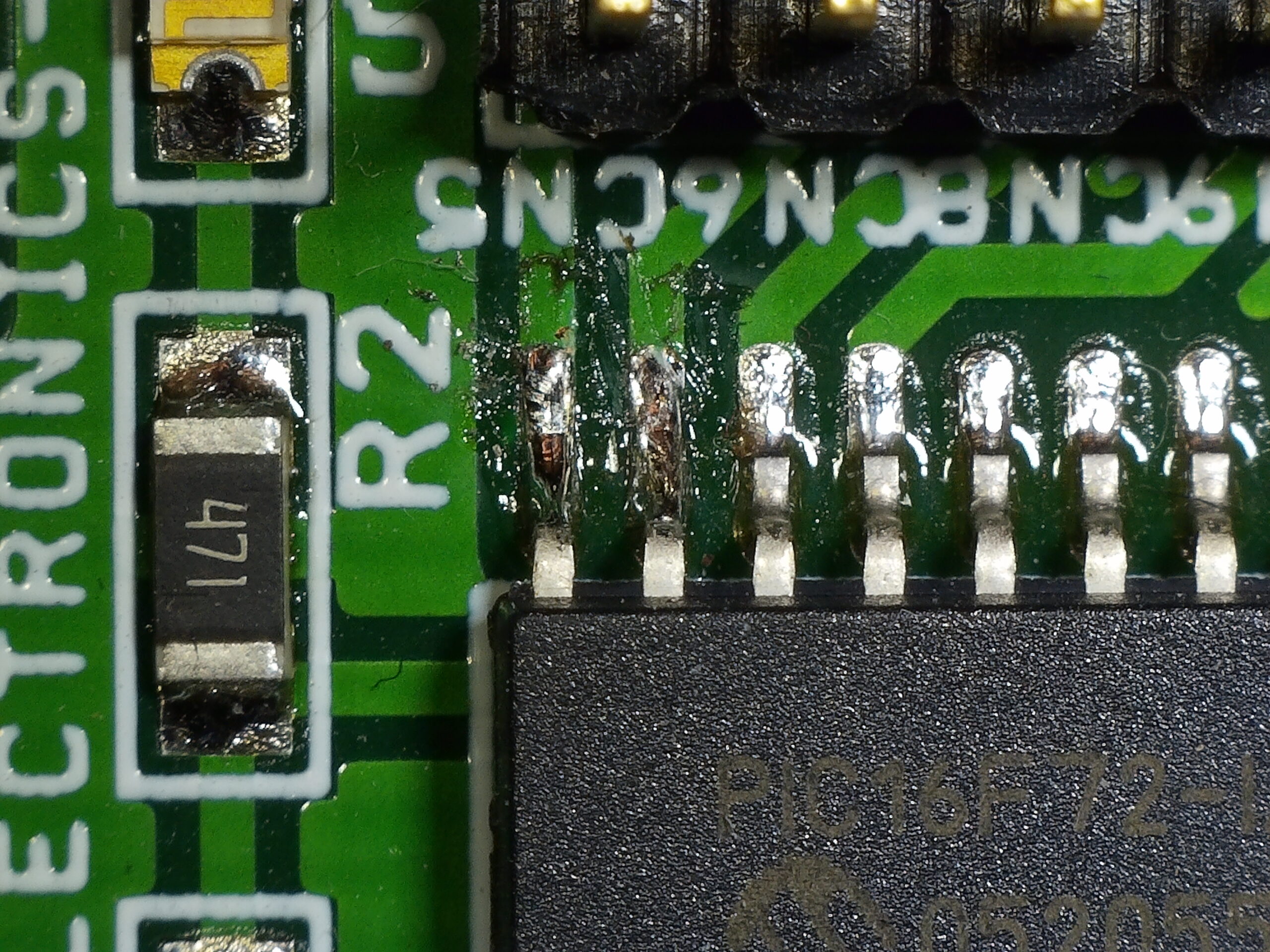
Sample Photos
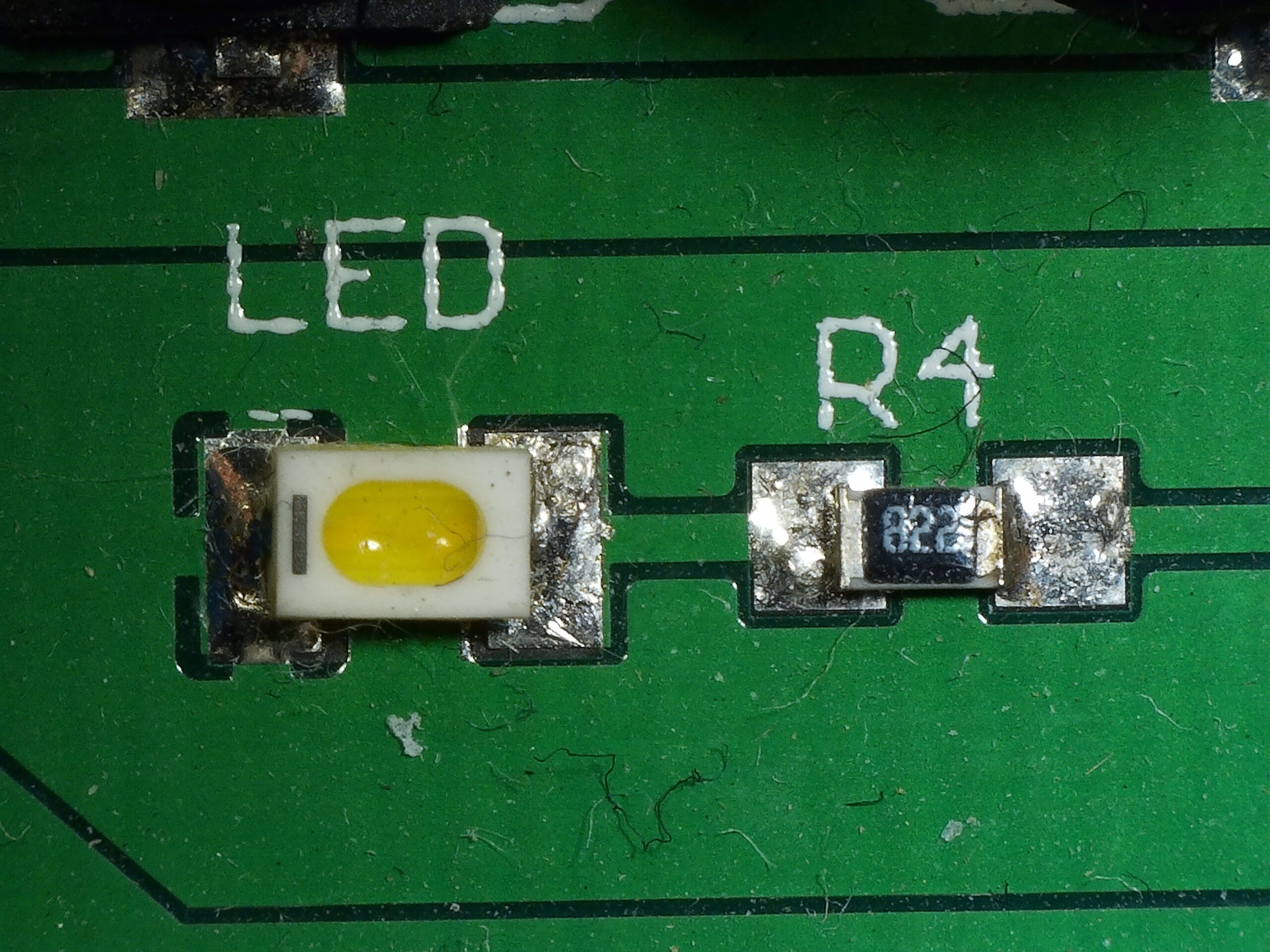
Here are some images captured on the SD card of the microscope. As you can see the quality is nice and the images are sharp and clear. Resolution of images is 4032 x 3024 px which is fair enough.
Downloads
In summary, the ADSM302 is a good and solid piece of equipment because of its full HD resolution, high object distance, multifunction abilities, multi-output at the same time. And also its appearance design combines more ergonomic consideration, provides user a better experience.
The ADSM302 is available for $179.99 on Banggood, and you can find more information on Andonstar’s product page.