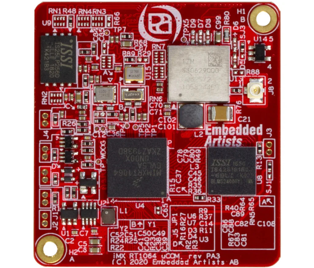
The i.MX RT1064 is one of the highest performing Cortex-M7 solution delivering 3020 CoreMarks (when running core at 600 MHz). In addition to the high-speed performance it provides fast real-time responsiveness and offer several low power modes.
This is a great option when microcontrollers no longer offers sufficient performance and there are reasons to not fully transfer into the Linux universe with an application processor.
Highlights
High-performing Cortex-M7, up to 600 MHz
Fast real-time response with ultra-low latency
On-board 1ZM Wi-Fi/BT option
Multimedia functionalities
The i.MX RT1064 has the most comprehensive multimedia functionality among our microcontroller modules including great audio, 2D video accelerator, pixel processing and camera sensor.
Wide range of connectivity options
There is an on-board Wi-Fi/BT option with Murata’s 1ZM (LBEE5QD1ZM) module, based on NXP 88W8987 chipset. It is a dual-band Wi-Fi 802.11a/b/g/n/ac + Bluetooth 5.1 module.
There is also a wide range of advanced off-board connectivity options with other Murata Wi-Fi and Bluetooth modules.
Temperature Range
Our iMX RT1064 uCOM board is available in commercial / industrial temperature range, 0 to +70 / -40 to +85 degrees Celsius. The industrial (temperature range) version is suitable for always-on applications.
Available in December 2020
The iMX RT1064 uCOM modules will be available in mid-December 2020 and supported with an iMX RT1064 uCOM Developer’s Kit. Contact Embedded Artists if you want early access.
It has always been a far fetched idea for the hobbyists to get hold of a good telescope and go observing the night sky and take various breathtaking pictures. There has been a very steep learning curve with the technicalities of space exploration. Also, the essential pieces of equipment are cumbersome and expensive. That’s why many give up on their hobby of exploring the night sky. A small company called Vaonis from New York is showing big promises for space observation hobbyists and enthusiasts with their Kickstarter campaign for Vespera.
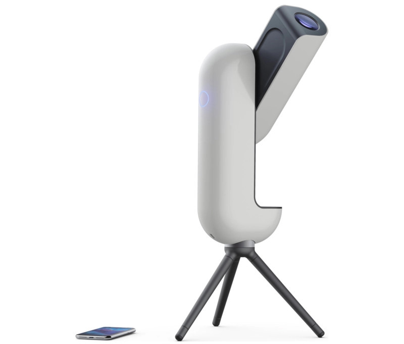
Vespera with adjustable leg tripod
Vespera is the combination of a telescope and a camera. It is smart and fully automated with the help of a mobile device combined with their app. With the help of this new smart device, the user can explore and observe the night sky along with capturing photos of celestial objects. It has a tripod with adjustable legs. It calibrates itself through the GPS and its so-called “Star Field Recognition technology“. The setup process is easy as that of selecting a celestial object in the app and clicking a button to start the automated tracking and observation.
The telescope used here is a custom made an optical design based on 4 lenses in 2 groups with a focal length of 200mm and 50mm aperture. They claim to have zero distortion, zero chromatic aberration and, zero astigmatisms. For the camera they are using, the 2MP Sony sensor IMX462 Starvis, enhanced with their custom-made electronic card. The brain of the system is a Raspberry Pi (undisclosed model) running their patented image processing algorithm to get the best out of the Sony sensor. As mentioned by the company, it has water resistance and an integrated battery with 4hours of backup.
The Orion Nebula, captured by the Vespera with an exposure time of 33
The Vespera has already surpassed the original Kickstarter goal by a significant amount. According to Vaonis the device should be arriving at the backers by Christmas of 2021. For a complete list of all available early bird pledges, stretch goals, and other information check their Kickstarter page.
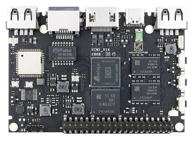
VIM1 is the original Amlogic S905X ARM development board designed by Khadas for hobbyists, makers and electronic lovers, which is also often referred to as an “Open Source TV Box”. It is tiny, and slightly smaller than a Raspberry Pi, with dimensions similar to that of a credit card. The VIM1 is only available in two versions: VIM1 Basic with 8GB EMMC storage and AP6212 (b/g/n) Wi-Fi, and VIM1 Pro with 16GB EMMC storage and AP6255 (b/g/n/ac) Wi-Fi. Both versions offer 2GB of DDR3 RAM and Bluetooth 4.2.
Like your conventional desktop computer, the VIM1 single board computer supports the booting of multiple operating systems. They say:
You can choose from a variety of OS images (ROMs) from our Khadas Docs or Community Forum. Popular OSes include: Android 7.1 / 9.0, Ubuntu 18.04, LibreELEC, Armbian, Buildroot, and so on. There are even dual-boot images, for developers to boot both Android and Ubuntu from the same EMMC.”
One feature developers will like is the built-in 40-pin GPIO, real-time-clock (RTC) and VIN port for an extra power supply. Also, the three user-buttons on the side enables easy access to power, reset and function keys. You can find full open source code on Github, and hardware schematics can be found in Khadas’ documentation. Khadas also includes a built-in power control unit for supporting power-cycling via a remote control.
Talking about the edge VIM1 has over VIM2, they say:
“In comparison with the Octa-Core Amlogic S912 SoC in the VIM2, the Quad-Core S905X SoC in the VIM1 generates significantly less heat. This makes the VIM1 especially useful in environments that only allow passive air convection for heat dissipation, rather than forced airflow. In many instances, a single heatsink is sufficient, and some users may even find a heatsink unnecessary for their applications.”
The VIM1 enables 2GB DDR3(1866Mbps), 8GB of EMMC V5.0, AP6212(b/g/n) Wifi, and Bluetooth:4.2. It supports USB Type-C USB2.0 OTG & 5V DC IN. The VIM1 HDMI 2.0a is Type-A Female, with up to 4K@60Hz, and it features a 12GB Max TF Card Slot. It also features a dual channel IR receiver. GPIOs includes:USBx2,I2Cx2,UARTx2,SPDIF,PWM,ADC,GPIOs. It is also equipped with Red+Blue LEDs indicators.
Khadas targets to develop high-performance SBCs with better quality for both beginners, makers, and developers, it comes with open source, professional technical support, and an global community for issue discussion & idea sharing. Khadas aspires to help the makers grow by achieving their ideas and dreams step by step.
Some of the prominent features includes:
Multi-O/S (Support Multi O/S Boot)
VIN Port for Extra Power Supply
Built-in RTC: Support timer on/off (Android testing method: Settings—>Timer)
40-Pin GPIOs, can be developed other kinds of products you want.
Technology Community Forum
Three user buttons: more easy for developers
Encryption chips
Full open source code on Github
Tiny size like a credit card 82.0 x 57.5 x 11.5 mm
Support cooling fan
Built-in power controller unit: Support power on/off via remote controller
USB2.0 HOST:x2(500mA & 900mA each respectively)
Mounting Holes:Size M2*4
The VIM1 is available on AliExpress for $44.99. More information about the VIM1 can be found on Khadas’ website.
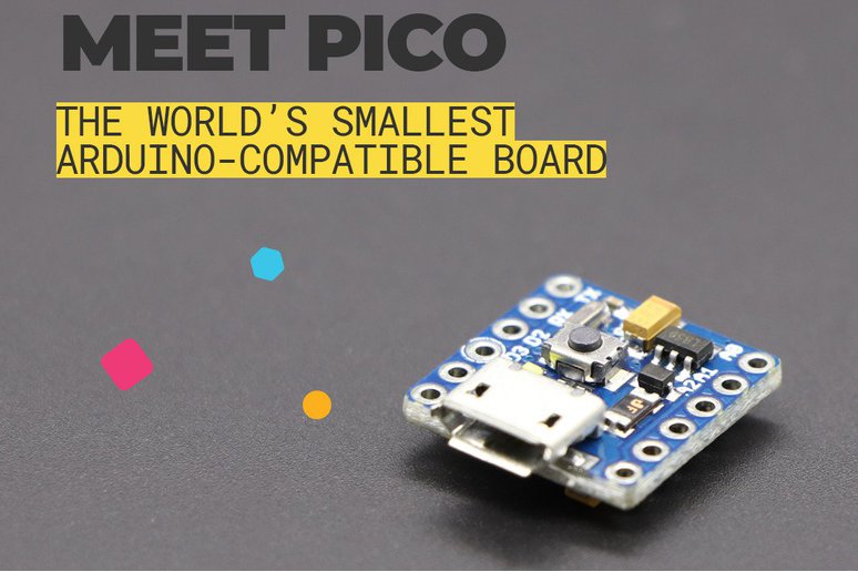
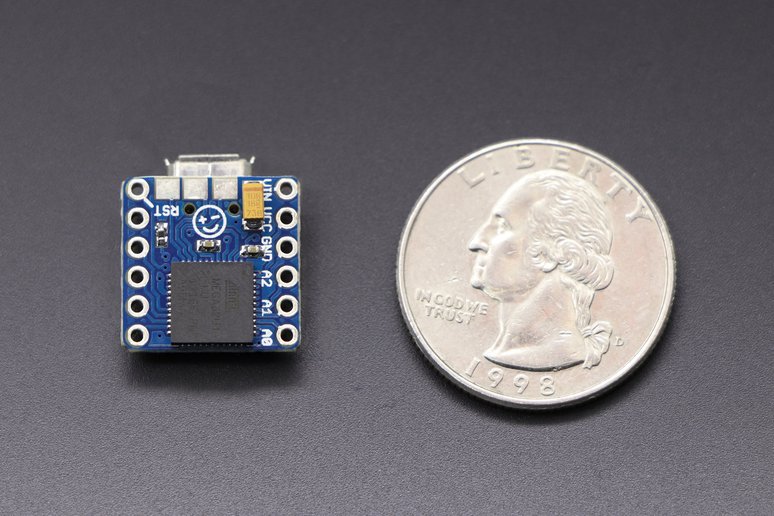
Recently, we have been getting some interesting downsizing when it comes to the development boards that we can use in our maker projects. What makes them so interesting is the fact that you can fit them anywhere and not worry about them, as they usually consume so little energy that even a small battery can run them for a long while. In that segment, we may have a new interesting addition: behold, the PICO!
But what is the PICO? Well, as you can probably guess from the name, it is the smallest Arduino compatible development board, designed by MellBell Electronics in the USA. The word smallest may ring a bell, due to our recent overview of the Adafruit QT Py. This PICO makes a mockery of that downsizing effort. Without taking the merit from the QT Py, as a really interesting product which has some interesting features (probably even more than the PICO), this one is almost half the size. We think the QT Py can be a good reference point to overview this one, as they intend to do mostly the same thing, which is shrink down your projects.
Regarding features, with the PICO we are looking at:
ATmega32u4 microcontroller, clocked at 16 MHz
32 kB of internal Flash (4 kB used by the bootloader) and 2.5 kB of SRAM
8x digital I/O pins, 1x PWM channel and 3x analog input channels. 3 SPI enabled pads on the back of the board
5 V operating voltage. Input voltage range from 7 to 12 V. 40 mA DC current per I/O pin
Bootloader compatible with the Arduino Leonardo
0.6 x 0.6 inches size. Weight of 1.1 grams
The PICO alongside a coin
Besides the incredibly small size, you get some interesting peripherals to work with, enabling you to do almost anything when you only need to think small! You also can make use of the Arduino platform, due to the PICO being compatible with it. When comparing to the QT Py, you lose some features, such as the I2C at hand, some I/O (including the stemma QT connector), besides the considerable downgrade in specs, which is not necessarily bad, as it will consume less energy and handle longer battery time.
Probably, the most dissuasive feature of the PICO is its price, when compared to the QT Py. When the QT Py comes at $6, the $17 dollar price tag placed on the PICO is considerable. Nevertheless, you can get it on Tindie an make your own opinion, as we still think it is worth at least to take a look at it, specially if you have been having problems with the size of your Arduino-based projects.
As technology changes from time to time, the need to deliver networks with high throughput and high efficiency becomes a major necessity. The latest generation of wireless network technology, WiFi 6 or 802.11ax offers not just faster speeds as generational changes, but higher-efficiency Wi-Fi for better coverage, improved capacity, and reduced network congestion.
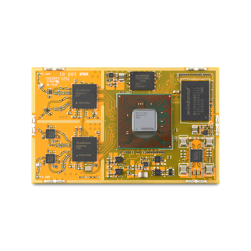
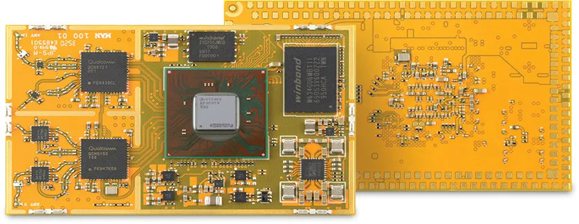
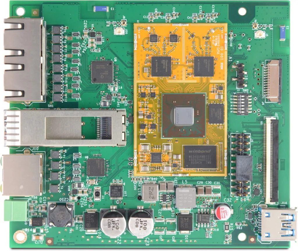
To provide developers with a platform that allows them leverage on the speed and efficiency offered by these new wireless technology, 8Devices has employed their many years of experience in hardware and embedded software to birth a WiFi 6 system-on-module and a corresponding WiFi 6 development kit called the Mango SoM and Mango DVK.
The Mango SoM is powered by Qualcomm IPQ6000/IPQ6010 quad-core Cortex A53 processor and supports high power dual-band 2×2 MiMo 802.11ax. It has many peripheral interfaces that can be configured as general-purpose I/O pins and others.
The SoM runs OpenWrt Linux and is considered ideal for routers, gateways, and access points. It is available in both the commercial and industrial temperature range (Mango and Mango-I respectively), in case you’d want to use it for applications that require extended temperature range.
Some features and specifications of Mango SoM include:
CPU: Qualcomm IPQ6000 / IPQ6010 quad-core Cortex-A53 @ up to 1.2 GHz / 1.8 GHz respectively, with NEON SIMD DSP extension.
Hardware NAT engine and high-end HW crypto
512MB DDR3L DRAM (up to 2GB)
32MB NOR FLASH
256MB NAND flash (up to 1GB)
2402Mhz – 2482Mhz 22 dBm 802.11 b/g/n/ac/ax WiFi 6 2×2 MU-MIMO, explicit beamforming and up to 573.5 Mbps
4920Mhz – 5920Mhz 21dBm 802.11 b/g/n/ac/ax WiFi 6 2×2 MU-MIMO, DL-OFDMA (8 users), explicit beamforming and up to 1021 Mbps
2x Ethernet SerDes that supports 6.25/5/3.125/1.25 Gbps Ethernet
2x 2.5GbE interfaces
5x 1Gigabit Ethernet ports
64x GPIO
4x Audio PWM, 2x SPI,1x UART and 1x I2C
1x PCIe 3.0
1x USB 2.0 and 1x USB 3.0
1x SDIO3.0/eMMC interface
1x Parallel NAND flash
1x Reset, and,
1x Display controller.
Commercial temperature range: 0 – 65°C
Industrial temperature range: -45 – 85°C
Dimensions: 38.3 x 61.7 mm
Features and specifications of Mango-DVK on the other hand include:
SoM: Mango-I WiFi 6 module (industrial-grade)
eMMC module socket
MicroSD card slot
2.5Gbps Ethernet RJ45 port plus PoE passive 24-48V
SFP cage
2x 1Gbps Ethernet interface
SFP port
2x WiFi antennas and 2x u.FL connectors for external antennas
1x USB 3.0 interface
2x Optional FPC power bus board-to-board connectors
2.54 mm GPIO header
mPCIe socket with PCIe 3.0 and USB 2.0
9-60V DC power supply
Optional power out pin header 3.3V and 5V.
LEDs, User, and Power buttons, and Configuration switch.
Dimensions: 100 x 115 mm
Both versions of the Mango SoM as well as the development kit are currently available for preorder; Mango $79, Mango-I $99 and Mango DVK $219. Further details like the product brief may also be found here.
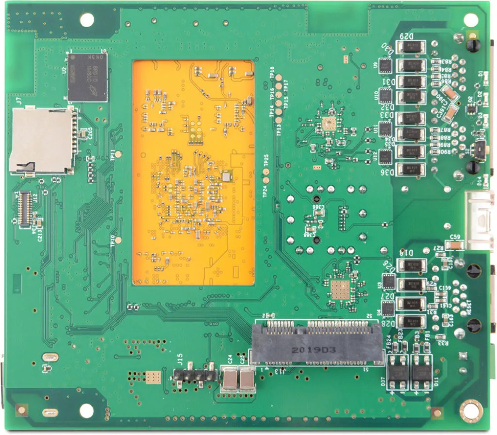
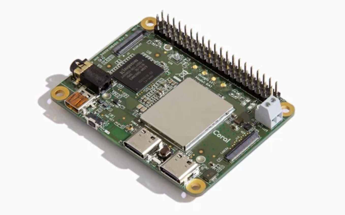
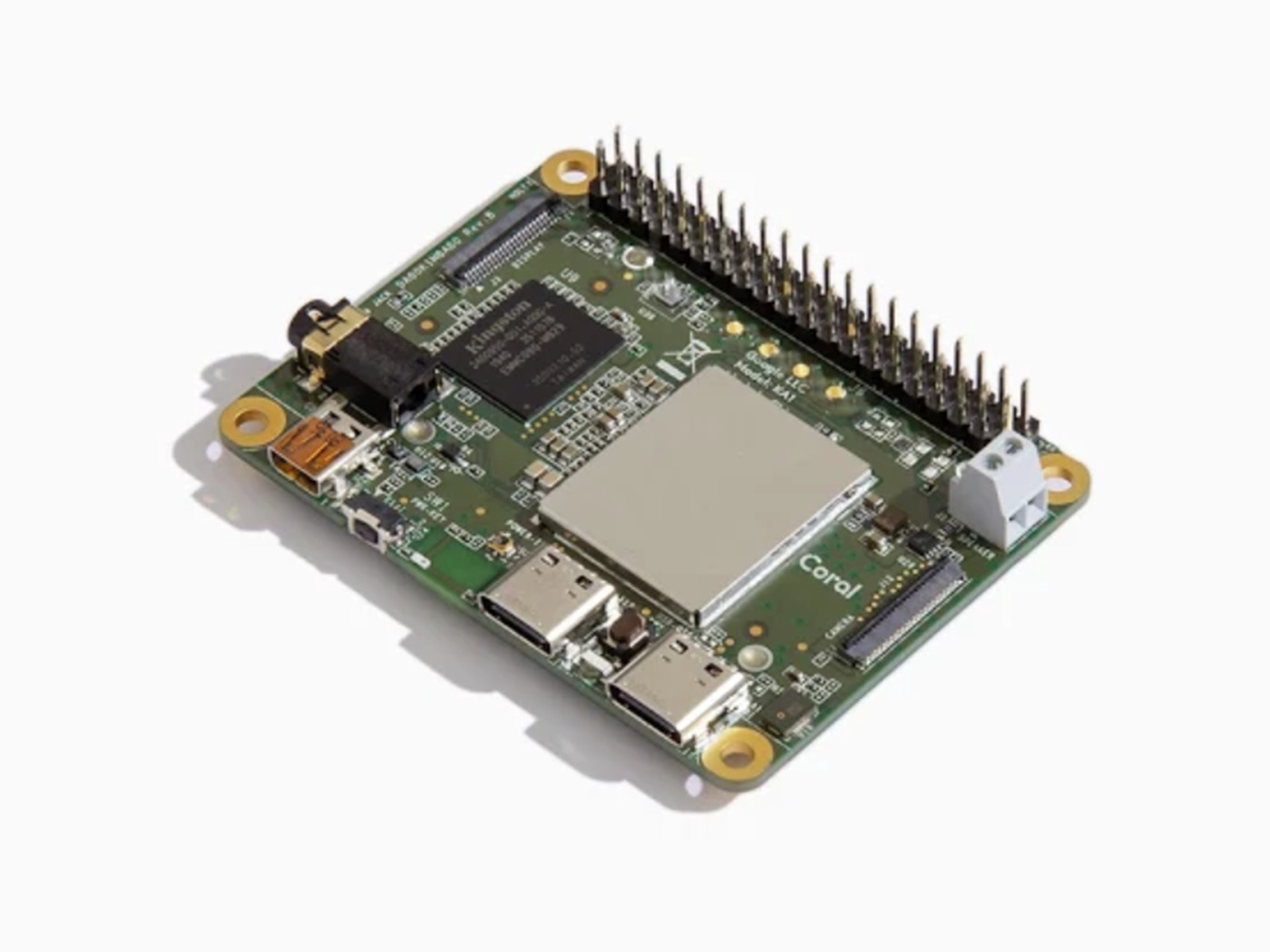
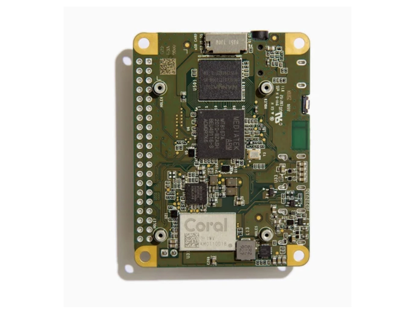
The Coral Dev Board Mini is a single-board computer that provides fast machine learning (ML) inferencing in a small form factor. It’s primarily designed as an evaluation device for the Accelerator Module (a surface-mounted module that provides the Edge TPU), but it’s also a fully-functional embedded system you can use for various on-device ML projects.
Features
Performs high-speed ML inferencing: The onboard Edge TPU coprocessor is capable of performing 4 trillion operations (tera-operations) per second (TOPS), using 0.5 watts for each TOPS (2 TOPS per watt). For example, it can execute state-of-the-art mobile vision models such as MobileNet v2 at almost 400 FPS, in a power-efficient manner. See more performance benchmarks.
Provides a complete system: A single-board computer with SoC + ML + wireless connectivity, all on the board running a derivative of Debian Linux we call Mendel, so you can run your favorite Linux tools with this board.
Supports TensorFlow Lite: No need to build models from the ground up. TensorFlow Lite models can be compiled to run on the Edge TPU.
Supports AutoML Vision Edge: Easily build and deploy fast, high-accuracy custom image classification models to your device with AutoML Vision Edge.
In our previous article about the Integrator op-amp, we have seen that the implementation of a reactive component significantly changes the electrical behavior of OPAMPs in comparison to fully-based resistive designs. Indeed, the presence of a capacitor in the feedback loop constitutes the main aspect of integrators, which perform electrically the mathematical operation of integration.
When the position of the capacitor is inversed, that is to say, that the feedback branch becomes resistive and the input branch reactive, a new configuration commonly known as a differentiator emerges.
The goal of the first section will be to present the general function of the differentiator op-amp and we will of course also demonstrate and explain its output formula.
Such as we have seen for the integrator, the ideal differentiator configuration that we focus on in the first section presents limitations that can be overcome with an alternative design. This limitation and it’s solution are both focused on the second section of this tutorial.
Presentation
The ideal differentiator
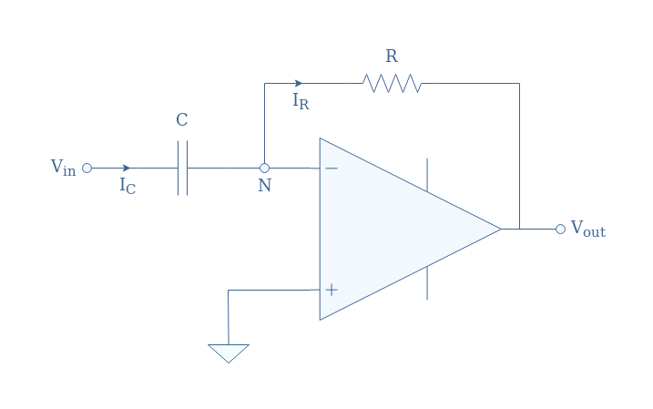
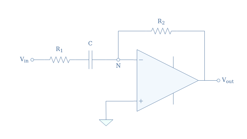
A differentiator is an inverting op-amp configuration in which a capacitor is present in the input branch such as shown in Figure 1 below:
We remind, as we properly explained in the integrator tutorial, that in the DC regime, a capacitor is equivalent to an open circuit while in the high-frequency regime it tends to be a short circuit as the frequency increases.
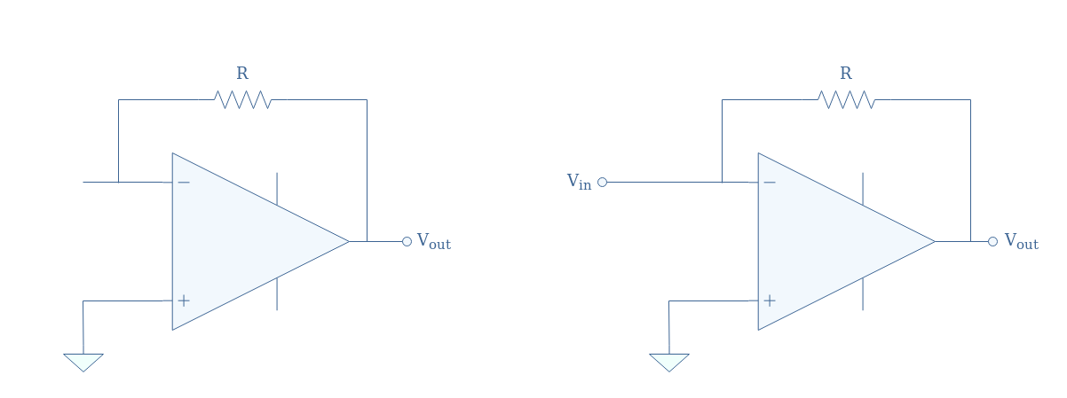
If we project this observation to the circuit shown in Figure 1, two different configurations can explain the behavior of the differentiator in low and high-frequency regimes:
fig 2: Equivalent differentiator circuit in DC regime (left) and in high-frequency regime (right)
In both cases, the differentiator can be reduced to an inverting op-amp and when the input signal frequency is very low the capacitor tends to block it. On the other hand, when the input signal frequency is high, it is directly supplied to the inverting op-amp input without any intermediary impedance.
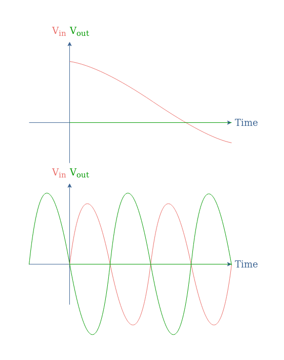
In other words, slow variations present in the input signal are not being amplified by this configuration, fast variations are however amplified and affect the output signal.
fig 3: Output signal as a function of the input variations
We can highlight that in the second Figure, the output signal is in phase opposition with the input signal.
Output formula
If we suppose the internal op-amp impedance to be very high or tending to infinity in the ideal case, the equality IC=IR is established. If we label this current “I”, it satisfies the input branch in the relation I=C(dVin/dt), moreover, the Ohm’s law in the feedback loop gives Vout=-RI.
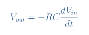
Therefore, the output relation of the differentiator is given by Equation 1 below:
eq 1: Output formula of the differentiator op-amp
Using the complex notation, Equation 1 can be simplified to Equation 2, which also gives the transfer function T:
eq 2: Transfer function of the ideal differentiator
These formulas clearly highlight the fact that the differentiator configuration performs the differentiation operation between the input and output.
AC Analysis
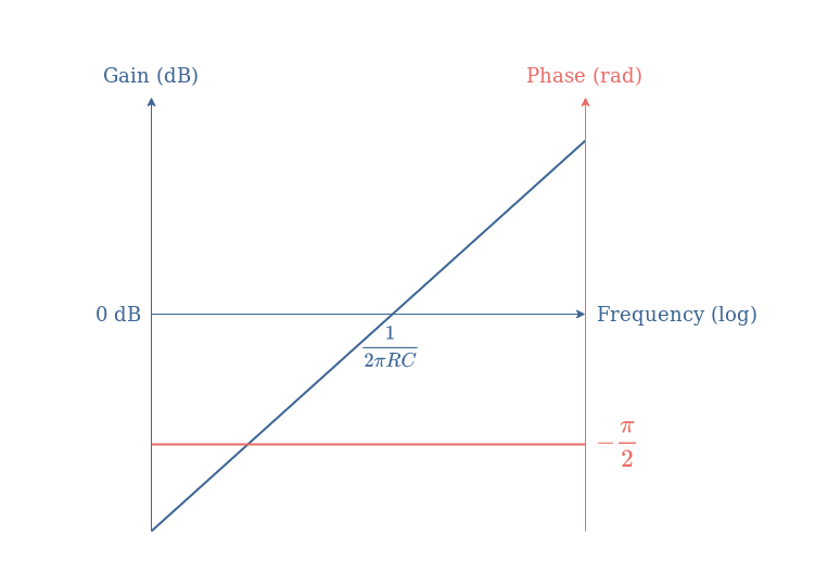
From Equation 2, it is easy to establish that the gain in dB of the ideal differentiator is given by +20log(x), moreover, the phase of a pure negative imaginary number is -π/2 rad.
From this information, the Bode plots of the ideal differentiator are given in the following Figure 4:
fig 4: Gain and phase Bode plots of the ideal differentiator
The real differentiator
Limitations of the ideal configuration
A major gain limitation arises from the ideal configuration. As we have seen in Figure 2, when the frequency increases, the circuit tends towards an inverting configuration with a gain given by -R/Rin (refer to the inverting op-amp tutorial). However, since the input is shortened when the frequency increases, Rin=0,the gain tends to infinite values.
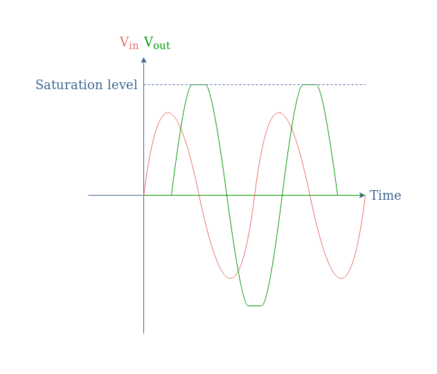
In practice, when the frequency of the input increases too much, a saturation will start to appear which limits the differentiation operation:
fig 5: Saturation phenomenon in ideal differentiators
Pseudo-differentiator with a series resistor
An improvement that can be made to the differentiator is to place a series resistor in the input branch. This configuration is referred to as a pseudo-differentiator SR (for series resistor).
fig 6: Pseudo-differentiator SR circuit representation
The equivalent circuit for high frequencies will be an inverting op-amp with a finite gain -R2/R1. As a consequence, in the high-frequency regime, when the capacitor impedance tends to zero, the gain will therefore be limited to R2/R1instead of ∞ which would make the output to saturate as pinpointed in the ideal circuit section.
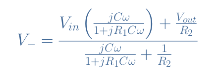
We can apply Millman’s theorem at the node N in order to analyze this circuit:
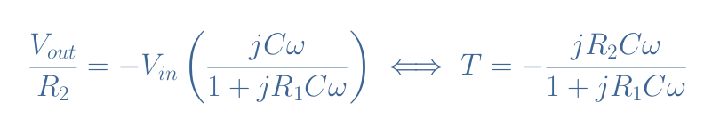
With the virtual earth hypothesis V–=0, we establish the transfer function T of the circuit in Figure 6:
eq 3: Transfer function of the pseudo-differentiator SR
For frequencies from DC up to the cutoff frequency 1/(2πR1C), the transfer function can be approximated to -jR2Cω, which is a similar form of the ideal differentiator transfer function. When the frequency increases and tends to infinite values, a good approximation of the transfer function becomes -R2/R1 which establishes a plateau for the gain.
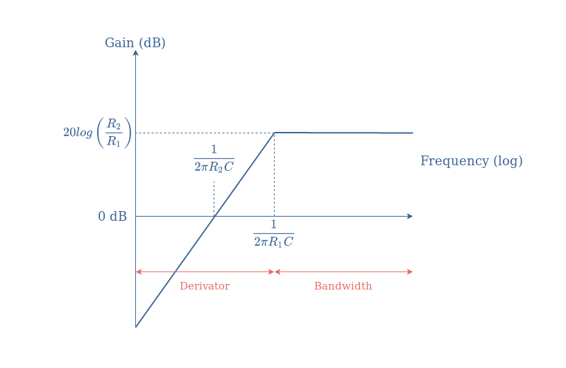
From these observations, the asymptotic gain Bode plot is given in Figure 7 below, which is typical of a high-pass filter:
fig 7: Bode plot of the pseudo-differentiator SR
We can conclude by saying that the pseudo-differentiator SR is a good approximation of the ideal differentiator up to the cutoff frequency of the circuit determined by the value of R1 and the capacitor C.
Pseudo-differentiator with a parallel capacitor
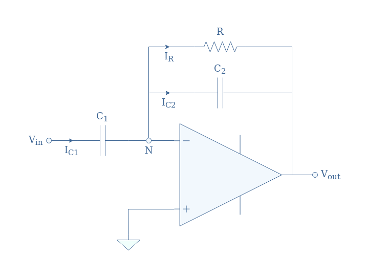
Another possible modification that can be applied to the ideal differentiator is to place a capacitor in parallel with the resistor in the feedback loop. The circuit presented in Figure 8 will be referred to as pseudo-differentiator PC (for parallel capacitor).
fig 8: Pseudo-differentiator PC circuit representation
Thanks to the capacitor C2, the equivalent circuit in the high-frequency regime is an inverting voltage buffer which means that the gain will be limited to the unity.
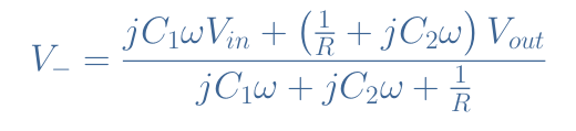
Let’s again apply Millman’s theorem at the node N:
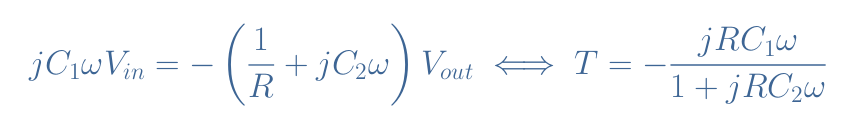
With the hypothesis of the virtual earth, the transfer function T of the pseudo-differentiator PC becomes:
eq 4: Transfer function of the pseudo-differentiator PC
For frequencies from DC up to the cutoff frequency 1/(2πRC2), the transfer function can be approximated to -jRC1ω, which is a similar form of the ideal differentiator transfer function. When the frequency increases and tends to infinite values, the gain of the transfer function reaches a plateau of absolute value 0 dB.
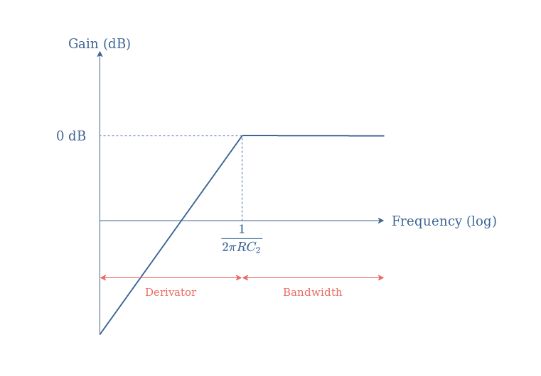
The transfer function of the pseudo-differentiator PC is again equivalent to a first-order high-pass filter such as we show in the following asymptotic Bode plot:
fig 9: Bode plot of the pseudo-differentiator PC
We can conclude by saying that the pseudo-differentiator PC is a good approximation of the ideal differentiator up to the cutoff frequency of the circuit determined by the value of R and the capacitor C2.
Conclusion
The mathematical operation “differentiation” can be realized by an electronic circuit called a differentiator, which is based on an operational amplifier working in inverting configuration with a reactive component in its input branch.
In the first section, we present the ideal differentiator which is a simple circuit to theoretically establish how a differentiator works. In particular, we pinpoint that due to the capacitor in the input branch, the circuit is equivalent to an inverting op-amp with a gain of 0 at low-frequency and a gain tending to infinite values in high-frequency regime.
The consequence of this electrical behavior is that an ideal differentiator can be characterized by a simple transfer function T=+jx, which means that its related Bode diagram is a linear plot with a slope of +20 dB/decade.
However, the ideal differentiator cannot be designed in practice due to the infinite gain the circuit is supposed to have when increasing the frequency. As a consequence, the differentiation operation is limited up to a certain frequency when the output will start to saturate.
Real circuits present either a series resistor in the input branch or a parallel capacitor in the feedback loop in order to limit the gain. “Pseudo-differentiators” as they are called are a good approximation of the ideal differentiator for a certain range of frequency that is determined by the value of their resistive and reactive components.
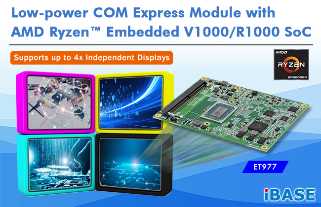
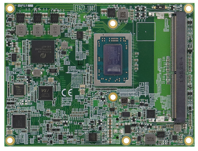
IBASE Technology Inc., a leading provider of industrial motherboards and embedded solutions, announces the launch of the ET977 low-power COM Express Compact Type 6 modules, which are based on the AMD Ryzen™ Embedded SoC to enable next-generation embedded designs. The series targets a wide range of applications including AIoT, retail, medical, transportation, automation and gaming fields.
“The ET977 COM Express module allows IBASE customers to deliver compact embedded solutions with a new class of performance and power efficiency,” said Wilson Lin, Director of IBASE Product Planning Department. “Built with the AMD Ryzen™ Embedded V1000/R1000 SoC, it is very suitable for modular designs and platforms that require high scalability to meet customers’ time-to-market needs.”
The new ET977 provides powerful computing with ‘Zen’ CPU cores and excellent image processing performance with the integrated AMD Radeon Vega graphics with 3 compute units to deliver stunningly visual experiences. It features four (V1000) or three (R1000) independent displays (HDMI/DVI/DP, LVDS or eDP) with up to 4K UltraHD resolutions and two DDR4 SO-DIMM slots for up to 32GB memory and with ECC compatibility.
The unit provides a wealth of advanced connectivity options including 2x serial, 4x USB 3.1, 8x USB 2.0, and 2x SATA 6Gb/s ports, as well as high-speed PCIe 3.0 lanes. Measuring 125mm x 95 mm, the Computer-on-Module is available in V1807B and V1605B variants for high computing and R1606G variant for low-power applications. Both Windows 10 and Linux Ubuntu are supported.
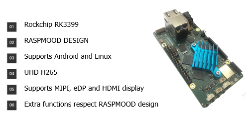
There’s a new member in the Novasom’s SBCs M-Line family
The SBCs M-line was created for those advanced multimedia applications, where the computing power and the presence of specific HW accelerators, are needed as much as the advanced connectivity to various kinds of displays while maintaining the classic low-level industrial connectivity.
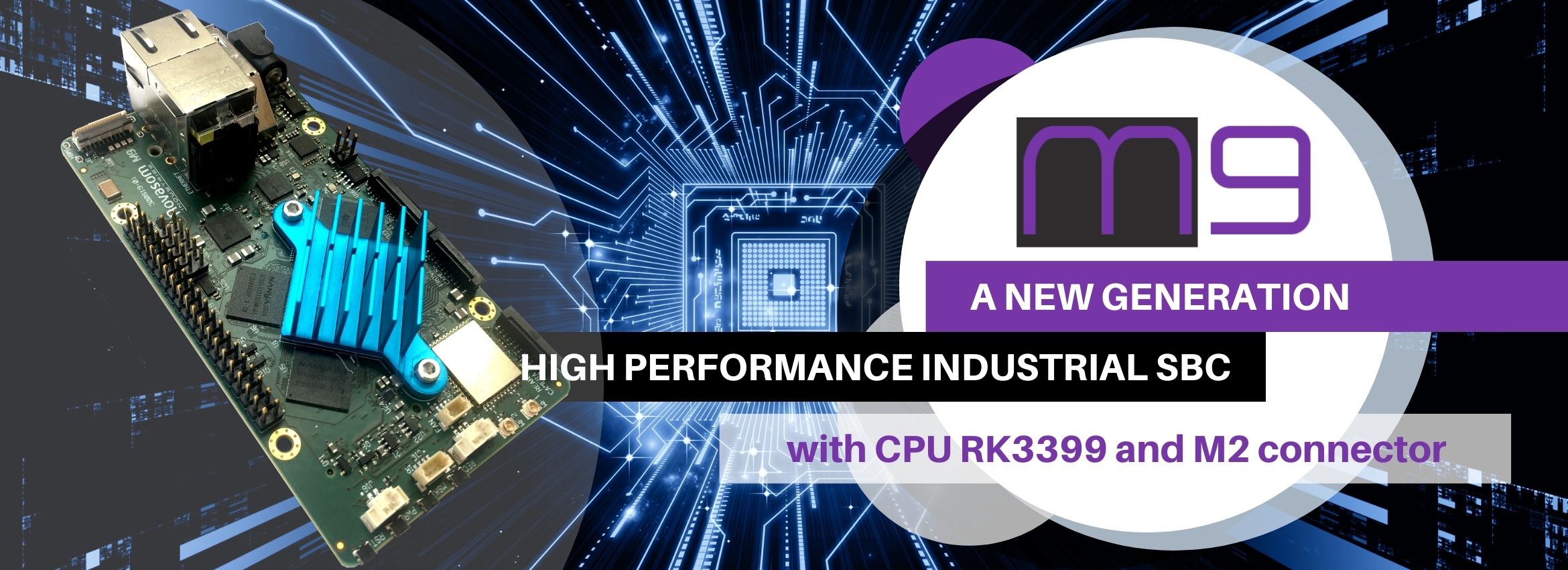
A new generation high performance industrial SBC
The latest product of the M-Line is Novasom M9 which joins the well-established M7 and M7Plus. This SBC is based on the prestige Rockchip 3399. This CPU offers the new Cortex A72’s performance and the multicore Quad A53 used to speed-up parallelism and lower consumption when needed, with one of the strongest GPU available on the market: the Mali-T860MP4. This board has been minded to offer the latest and strongest video input-output capability, while minding to our RASPMOOD approach with USB extender and low level GPIO to assure the compatibility with the famous community board’s started application.
As any Industrial Novasom’s SBC, the unit is equipped with our famous protected power supply, minded as industrial in terms of emission, susceptibility, mission profile and assisted by our technical support that will assure the success of your application. This is an Android-graphics oriented minded SBC, offering a superior fluidity experience for any tablet like or digital signage application.
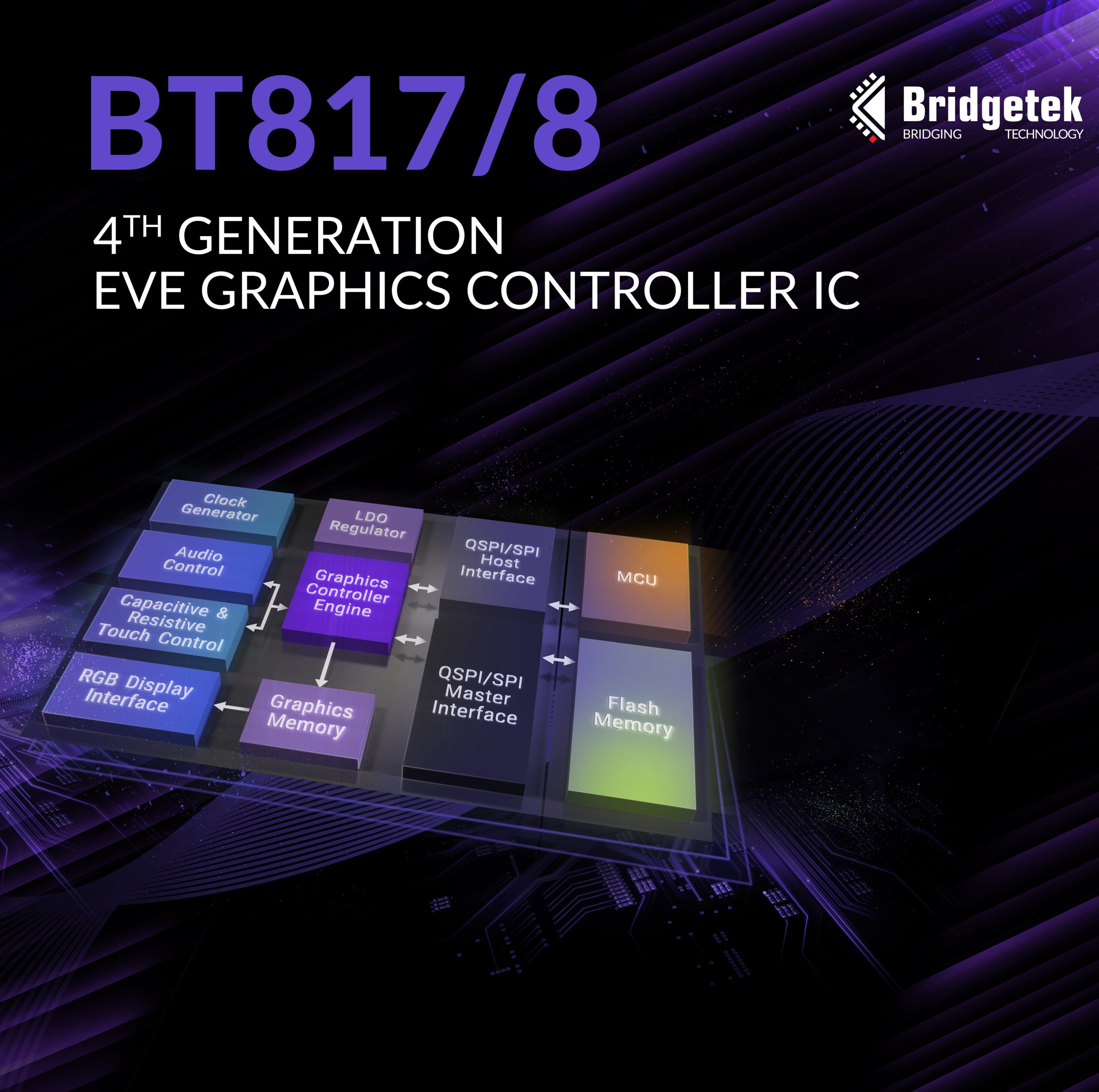
Driving forward the progression of human machine interface (HMI) development, Bridgetek has made further announcements relating to its multi-award winning embedded video engine (EVE) platform. The BT817 and BT818 represent the company’s fourth generation of EVE products, and follow the already established mantra of helping those with little or no relevant prior experience to build advanced HMIs with high degrees of differentiation.
These new functionally-superior graphic controller ICs are intended for use in retail, digital signage and office management systems, as well as public information units, vending machines, domestic appliances, store/mall direction finding systems, training/educational equipment and interactive exhibits. They are able to address the requirements of HMIs rendered on much larger format displays and offer greater resolution levels too.
Suitable for use with 1Mpixel displays, the BT817 and BT818 support resolution numerous options – such as 1920×480, 1440×540, 1280×800, 1024×600, 800×600, 800×480, 480×272, etc. Each has a 1Mbyte embedded graphics RAM, and this can be supplemented by attaching an external NOR flash memory through the QSPI interface. Thanks to the object-oriented approach pioneered by EVE, there is no need for a frame buffer to be incorporated into the HMI system. In addition, by leveraging adaptive scalable texture compression (ASTC), it is possible to lower the system’s graphics processing overhead. This also means better use can be made of the available data storage capacity, so that bigger items can be accessed and more compelling HMI content delivered.
The BT818 is optimized for use with 4-wire resistive touchscreens, while the BT817 has been designed to accompany capacitive touchscreens (with multi-touch functionality allowing detection of up to 5 different touch points). Touch point movement can be accurately tracked and there is the scope to assign 255 different touch tags. The ability to adjust both the horizontal and vertical sync timing means that a much wider array of different display units can be accommodated. Power mode control ensures that electricity consumption is reigned in. Other notable features include video playback, enhanced sketch processing and a built-in sound synthesizer.
“EVE, and the unique object-based architecture that it relies upon, has already made a huge impact on the way that HMIs are now constructed, with the display, touch and audio aspects all being addressed via a single chip. It has streamlined the whole process and reduced the bill-of-materials costs involved significantly,”
states Bridgetek’s founder and CEO Fred Dart.
“Through the latest additions to this product family, we can assist our OEM partners in bringing touch interaction to a plethora of new applications where larger format displays are employed.”
The Bridgetek BT817 and BT818 are supplied in compact 9mm x 9mm 64-pin VQFN packages. An extended -40°C to 85°C operational temperature range allows them to be deployed within industrial environments.