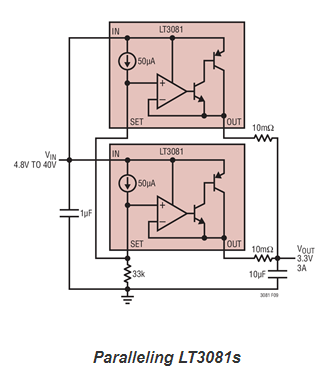
Various configuration of linear regulator for parallel operation discussed in this technical article from Analog Devices.
Linear regulators provide a simple, low noise solution for dc-dc regulation. However, at higher VIN-VOUT differentials the low efficiency and high power dissipation of linear regulators limits the amount of output current that can realistically be delivered. Connecting multiple linear regulators in parallel spreads the load (and the heat) over several ICs, increasing the useful range of output currents a solution can deliver. However, connecting linear regulators in parallel is not always straightforward.
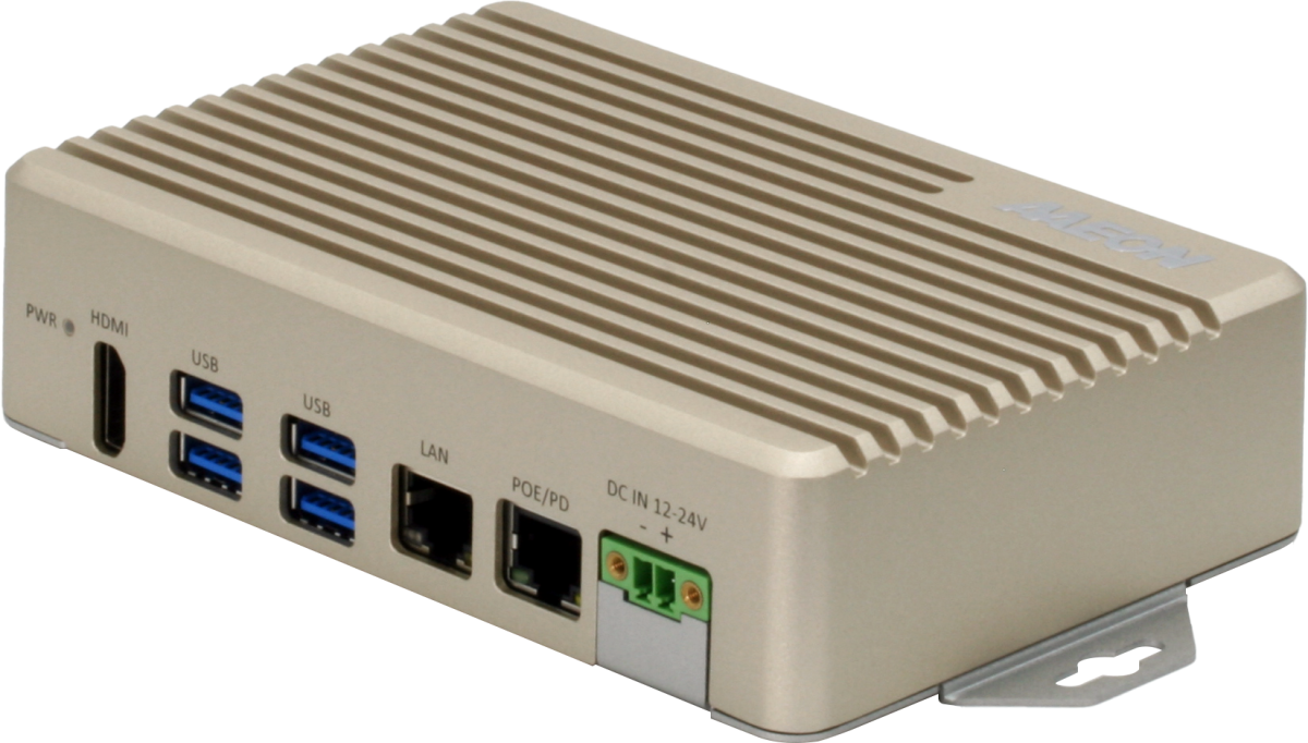
AAEON, an industry leader in AI Edge Computing, announces the BOXER-8222AI compact system powered by NVIDIA® Jetson Nano™. Featuring a PoE PD LAN port, the BOXER-8222AI can be powered by a PSE Gateway allowing for deployment without requiring a dedicated power supply.
The BOXER-8222AI is the latest platform in AAEON’s family of compact rugged AI systems powered by the innovative and energy efficient NVIDIA Jetson Nano SoC. Specialized for AI edge computing, the Jetson Nano utilizes the quad-core ARM® Cortex®-A57 MPCore processor with NVIDIA Maxwell™ GPU architecture featuring 128 NVIDIA CUDA® cores. This innovative design allows processing speeds up to 472 GFLOPs and is capable of operating multiple neural networks or processing several high-resolution images at the same time. The NVIDIA Jetson Nano also features onboard 4GB RAM and MicroSD card slot supporting up to 32GB of storage.
The BOXER-8222AI is unique in its design by featuring a PoE PD (Powered Device) LAN port. This allows for deployment without a dedicated power supply by connecting with a PSE Gateway (Power Supply Equipment). The BOXER-8222AI utilizes the 802.3at standard, supporting power input of 25.6W, more than enough to power the system and connected devices such as USB cameras and sensors.
The BOXER-8222AI also features a flexible I/O loadout including a 40-pin I/O connector designed to support a wide range of sensors and controllers. It also features four USB3.2 Gen 2 ports, RS-232 COM port, as well as LAN, CANBus and HDMI ports. The BOXER-8222AI also supports Wi-Fi expansion with an onboard M.2 2230 slot.
The BOXER-8222AI is designed to operate in a range of rugged environments, featuring a fan-less design to ensure reliable operation. It can operate in temperatures from -10°C up to 70°C without a loss in performance. Its compact size also makes it easy to deploy in tight spaces, putting it closer to where it’s needed.
AAEON offers industry leading service and support with the BOXER-8222AI, from providing technical support to end-to-end solutions to help reduce deployment times and shorten time to market. AAEON also offers manufacturer and OEM/ODM services to help with creating custom configurations, or designing systems from the ground up.
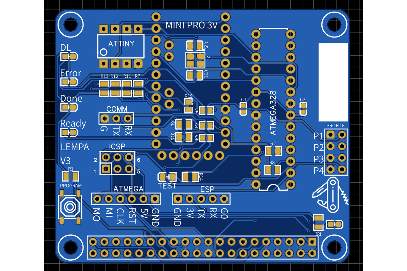
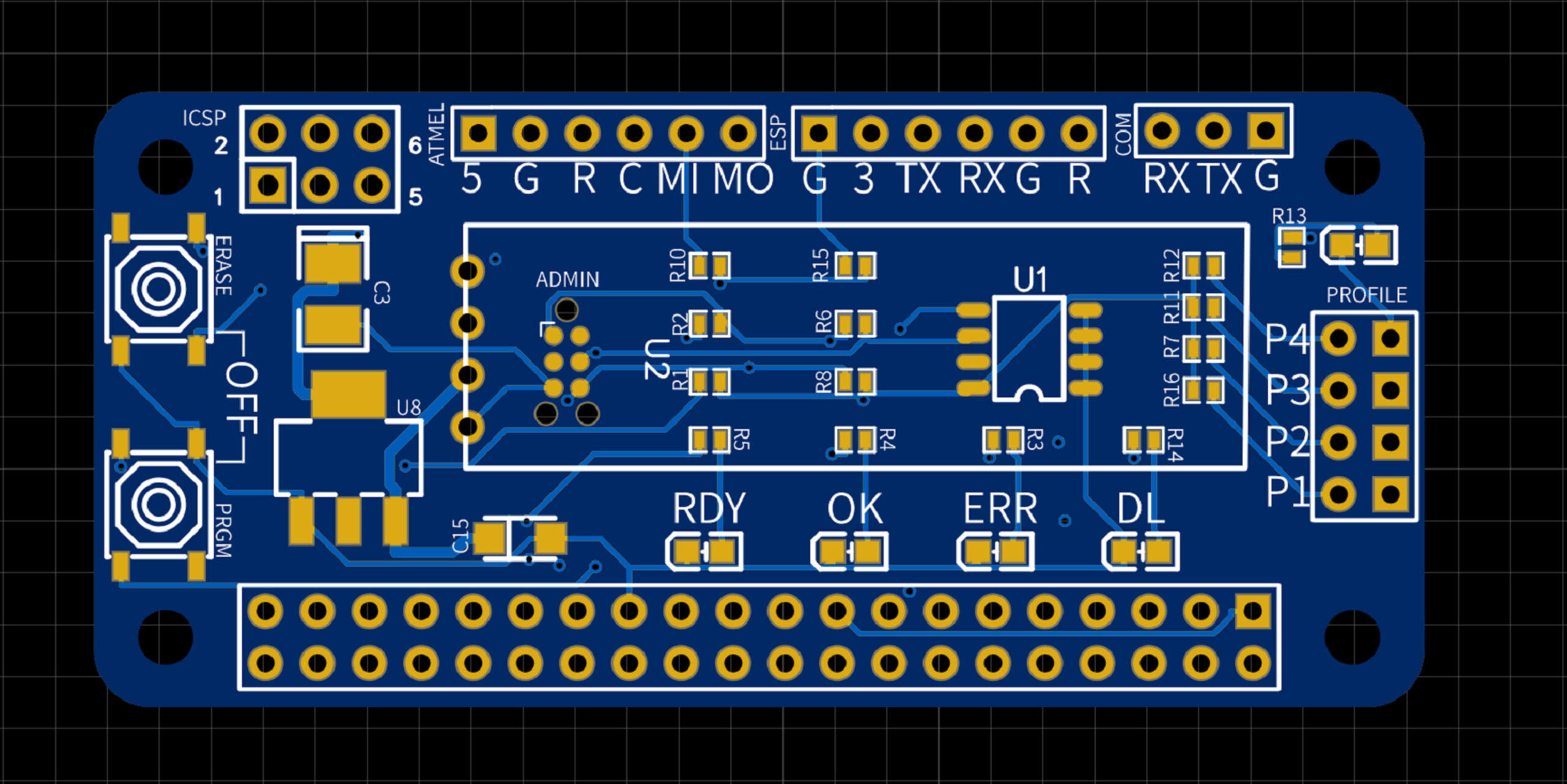
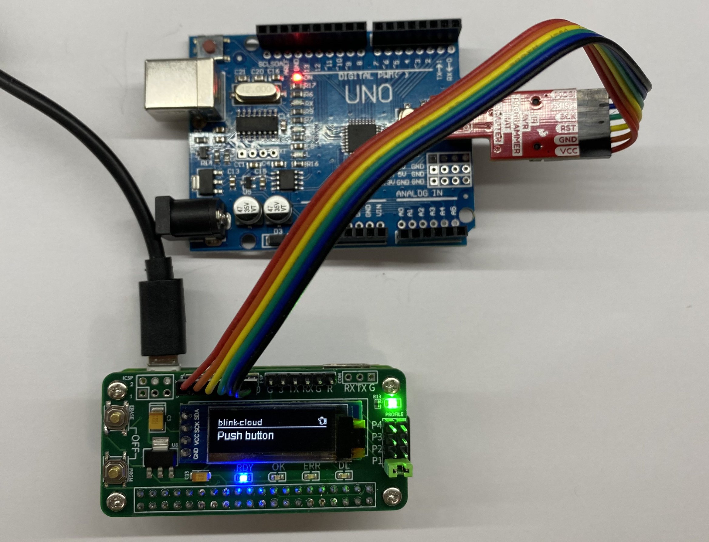
One of the challenges of developing and producing microcontroller-based hardware projects in a repeatable, small/medium volume, is the amount of work it takes to flash the MCUs with the required firmware. Another side of the problem for designers who work with diverse types of microcontrollers is the number of different kinds of programmers they need to have to be able to program the different microcontrollers successfully. Sensing this plight and desiring to provide a better experience for designers, Georgia Based Roey Benamotz’s recently announced the launch of his new integrated MCU programmer called LEMPA.
Designed as a Raspberry Pi HAT with the desire for a Pi or other Pin Compatible SBC to serve as the host device, LEMPA provides an easy way for developers to program Microchip Atmega/ATtiny and ESP Microcontrollers with full support for CI/CD and onboard LEDs that provide visual feedback during firmware upload.
The HAT comes with; a ZIF socket to allow for quick insertion and removal of the target DIP-type MCUs, a connector/Socket for ATtiny microcontrollers, and headers for an Arduino Pro Mini dev board. Asides from the LED that provides visual feedback during firmware upload, the board also comes with another LED that can be used to test for the success of the flashing process.
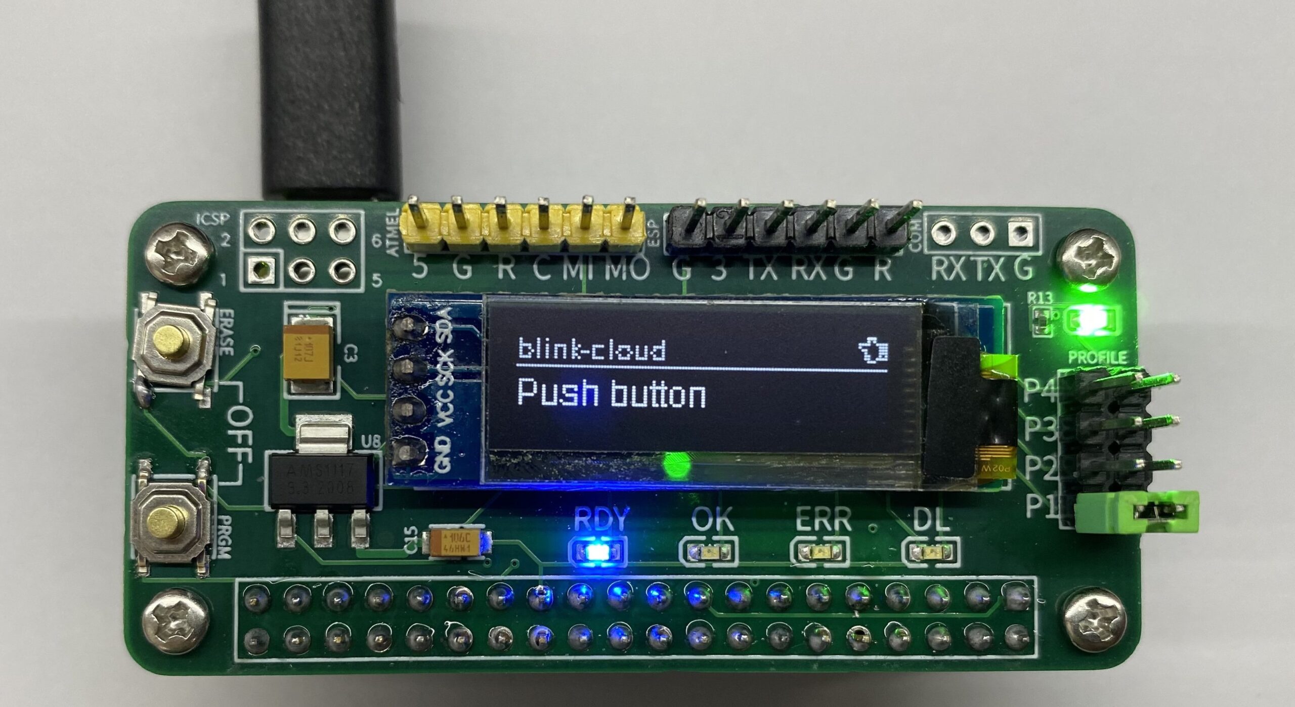
Inline with the goal of the project being to create an integrated tool that enables easy and fast firmware upload, Benamotz also developed a Python-based software that can pull firmware updates from a remote server and handle profile management and flashes the target MCU with the firmware using AVRdude. The software, which runs directly on the Raspberry Pi and other compatible SBCs, makes LEMPA a complete wireless standalone solution without the need for users to connect it to a separate PC to upload firmware, ensuring very little/no wire mess is made.
For repeatability of the firmware upload process, once the setup has been done, to upload firmware, all the user needs to do is to use the jumper on the HAT to select a profile, and press just one button on the HAT to initiate the firmware upload process.
Some highlight features and specification LEMPA(LEan Mean Programming mAchine) include:
Self-contained – no need for PC
Full support for CI/CD – binaries automatically downloaded from cloud or local network
Single-button: One click to program the MCU, long click to download the latest firmware
Support for multiple profiles with the simple editing of a JSON file. A jumper on board chooses which profile to use.
Fully open-source
Does not require cumbersome FTDI adapter or similar
Embedded LEDs provide immediate feedback without the need for a monitor.
While the LEMPA HAT is currently available for sale on Tindie for $19.99, the LEMPA Software is entirely open source and all the code files are available on the project’s Github page here.
More information on LEMPA may be found on the product’s Tindie page which also contains a video that shows how the project works.
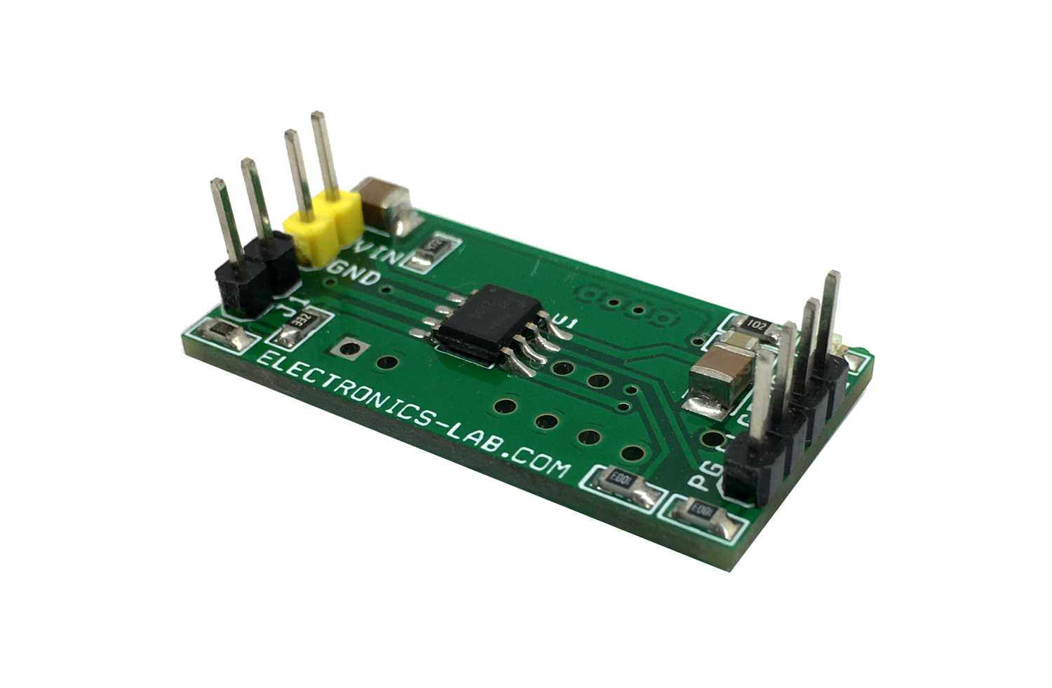
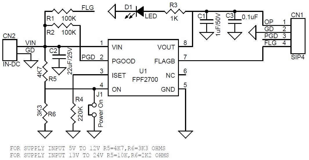
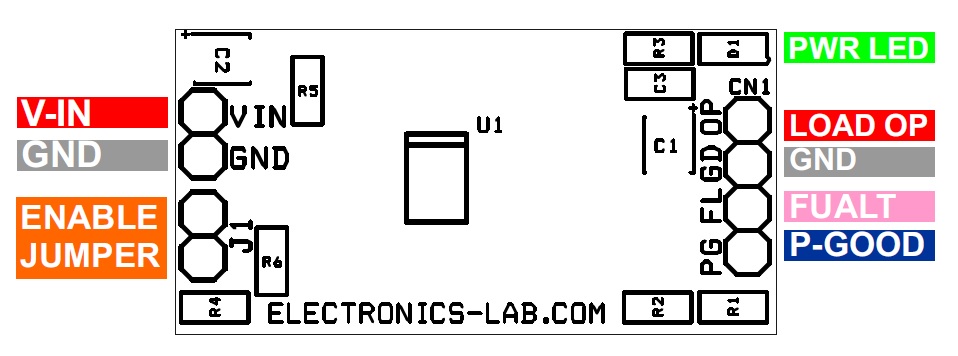
The Over-current limit load switch project presented here provides full protection to devices and loads from access load conditions. The default current limit is set to 1 Amp, however, this load limit is adjustable from 0.4A to 2A with the help of R4 ISET resistor. When an overload condition occurs circuit responds to that overload condition that lasts longer than a fixed blanking period by turning off the load, followed by a retry after the auto-restart time, auto-retry time is 127.5ms. Flag output is pulled up with R1 and the board provides active low output in a fault condition, normally Flag output is high. Power good output is also pulled up and it’s an open-drain output to indicate that the output voltage has reached 90% of the input voltage. The input range of this circuit is 5V to 24V DC. The load can be activated or deactivated with low-voltage logic compatible on Pin4, jumper J1 is provided to activate or deactivate the output. Close the jumper J1 to activate the output load.
An under-voltage condition on the input or if junction temperature is in excess of 140-degree centigrade overrides the ON control and turns OFF the switch. In addition, an over-current condition causes the switch to turn OFF. After the expiration of the blanking time, the IC has an auto-restart feature that automatically turns the switch ON again after the auto-restart time of 127.5ms.
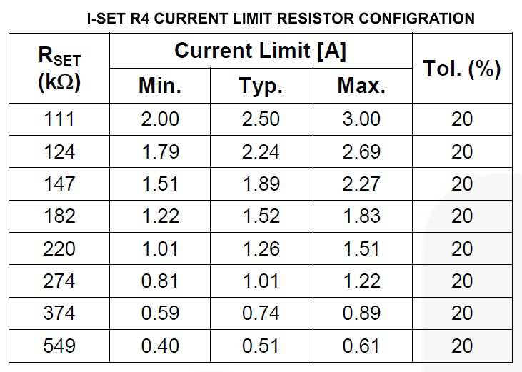
It is important to choose the appropriate value of resistor R5 and R6 which is dependent on the operating power supply, choose R5 4K7 and R6 3K3 for supply input 5V to 12V, alter these resistors value R5 10K and R6 2K2 ohms for supply input 13V to 24V DC. Voltage ON pin 4 should not exceed 5.5V. Default current limit is set to 1A, refer (I-Set resistor R4) table for the current limit set.
The FPF2700 over current limit switch is designed to meet the power requirements of a variety of applications with a wide input voltage range 2.8V to 36V and adjustable current-limit value. while providing optimum operation current for safe designed practices. The core of the switch is a typical 88mOhms (V=12V)
The N channel MOSFET and controller is capable of functioning over an input voltage range of 2.8V to 36V. FPF offers adjustable current limiting, under-voltage lockout, power-good indicator, fault flag output, and thermal shutdown protection. In the event of an over-current condition, the load switch limits the loads to the current value. The current limit value of the switch can be adjusted from 400mA to 2Amps trough the ISET pin. The enable pin is active LOW for and controls the state of the switch. Pulling the ON pin continuously to LOW holds the switch in on state. The switch moves into the OFF state when the ON pin is pulled HIGH. The ON pin can be pulled HIGH to a maximum voltage 5.5V.
Features
Operating Supply 5V to 24V DC
Load Current Limit 1Amps (Adjustable Range 0,4A-2A)
In most of the previous operational amplifier tutorials, the circuits had a feedback loop to the inverting input. This design is the most common because it provides indeed stability and avoids undesirable saturating effects and, it is also common to call it the linear mode.
On the other hand, when no feedback is applied to the inverting input, the op-amp is said to work in the non-linear regime, we can also say in an open-loop configuration. Comparators are specific op-amps circuits that are meant to work in a non-linear mode and can be used as simple logic gates.
A presentation of the circuit along with the basics about comparators is given in the first section.
In the second section, we increase the complexity of the circuit in order to show how to translate the so-called “tipping point” or “threshold” of the comparator. We show that being able to translate this value is important in order to properly design level detectors.
Schmitt triggers are discussed in a third paragraph, we will see how this kind of comparators work and how they can be used in real applications. Moreover, we highlight their advantages by comparing them to basic comparators.
Presentation
Non-inverting comparator
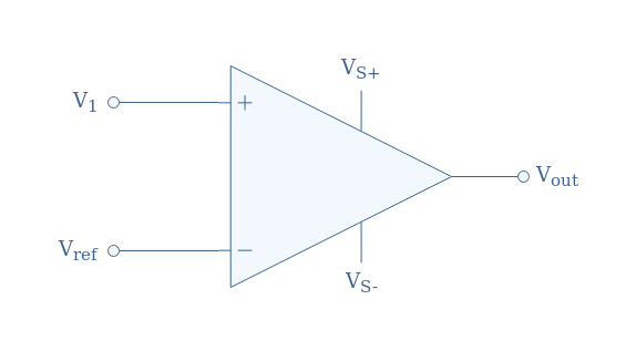
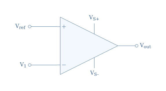
The simplest comparator consists of an op-amp without any resistor or feedback loop, the signal to compare is V1 and supplies the non-inverting input, a reference signal Vref supplies the inverting input, the output is labeled Vout and the supply power is VS+ and VS-, which can be symmetrical or not.
During this presentation section, we will pose and admit that Vref constitutes the ground, and therefore Vref=0. Moreover, we will admit that the supply is symmetrical (VS+=-VS-).
The functioning of this circuit is extremely simple and can be summarized depending on the value of V1:
If V1>Vref, Vout=VS+
If V1<Vref, Vout=VS-
The absence of feedback to the inverting input makes the amplifier to saturate up to the supply power level when the differential input Vin=V1-Vref=V1 becomes slightly higher than zero in absolute value
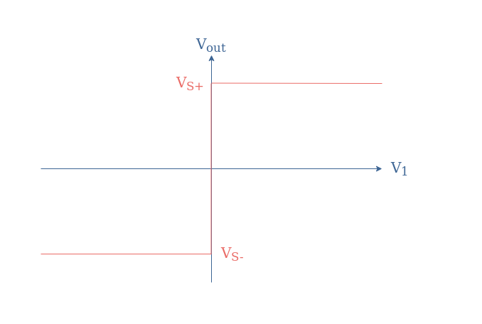
The input/output characteristic associated with the circuit of Figure 1 is a Heaviside-like function shown in Figure 2 below:
fig 2: Transfer characteristic of the non-inverting comparator
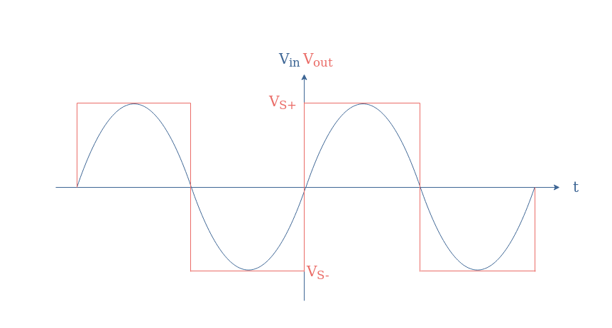
If a sine waveform is applied as an input, the comparator can be used to convert a sine to a square signal:
fig 3: Time-dependent output of a comparator with an input sine
Inverting comparator
In the previous subsection, the signal to compare was applied to the non-inverting input while the reference was on the inverting input of the op-amp. However, the roles can be inverted in order to get an inverting comparator such as presented in Figure 4:
In this case, the value of the output is dictated by these two conditions:
If V1<Vref, Vout=VS+
If V1>Vref, Vout=VS-
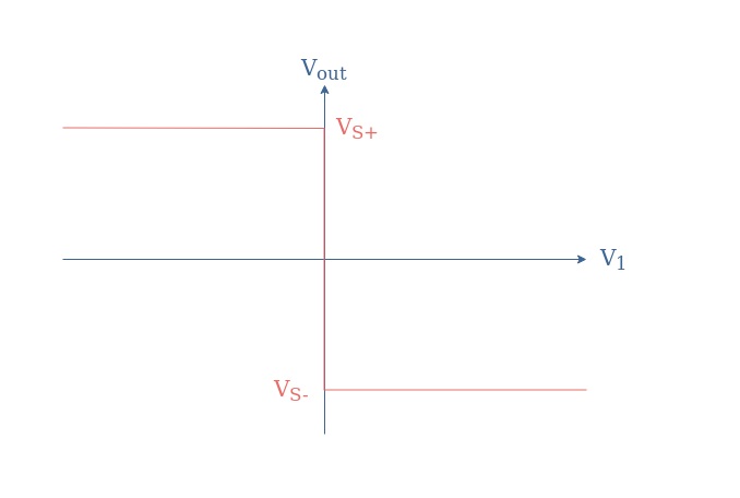
The transfer characteristic for this configuration is also a Heaviside-like function but with the positive saturation happening for V1<0 and the negative for V1>0:
fig 5: Transfer characteristic of the inverting comparator
Translation of the tipping point
Some complexity can be added with a voltage divider in the reference branch to either the non-inverting or inverting comparator in order to translate the tipping point. The tipping point is the value of V1 for which the output suddenly changes from a high (resp. low) to a low (resp. high) value. In the previous section, the tipping point was always happening for V1=0.
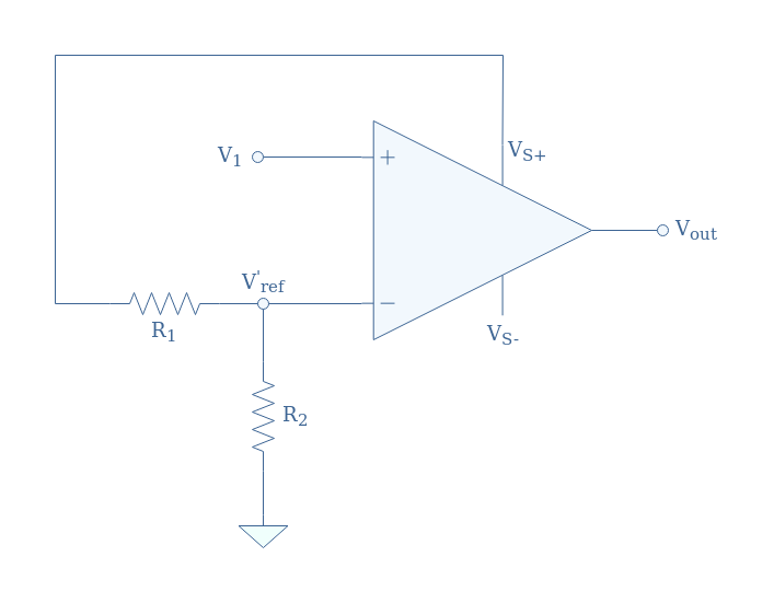
Let’s consider the comparator presented in Figure 6:
fig 6: Non-inverting comparator with a positive tipping point
Thanks to the voltage divider, an alternative reference voltage labeled V’ref is supplied to the inverting input of the op-amp. This new reference satisfies the voltage divider formula: V’ref+=+VS(R2/(R1+R2)). Note that the voltage divider can also be supplied with the negative power supply VS-, in that case, the alternative reference presents a negative sign (we label it V’ref-).
These observations can be summarized in the following transfer characteristics:
fig 7: Transfer characteristics of the non-inverting comparator with positive (left) and negative (right) tipping point
If we consider an inverting comparator, the effect of the same voltage divider circuit will have the opposite effect. Indeed, if the voltage divider is supplied with the positive (resp. negative) power supply, the translation of the tipping point will be negative (resp. positive). Moreover, the signal is inverted such as presented in Figure 5.
Time-dependent input
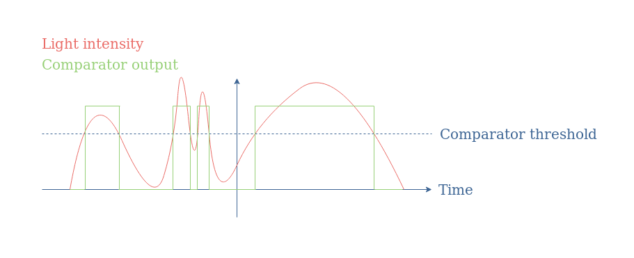
The translation of the tipping point allows setting the threshold level of the comparator to a non zero level. When a variable input is applied to the circuit, such as the output of light or temperature sensor, a simple level detector can be made with this basic comparator.
fig 8: Functioning of a level detector
Schmitt trigger
Non-inverting trigger
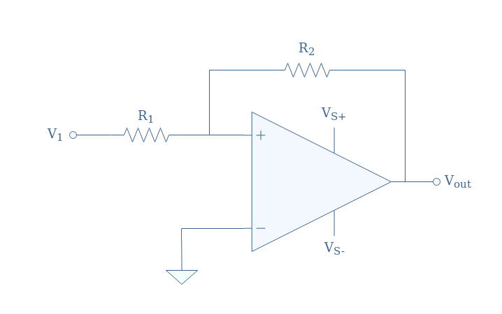
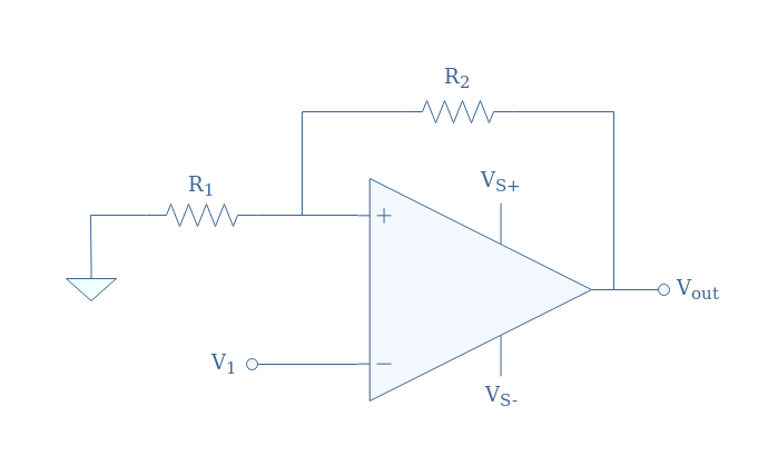
The translation of the tipping point can also be realized by adding a voltage divider circuit as a feedback loop in the non-inverting branch, the inverting branch is grounded (Vref=0). The full configuration is shown in Figure 9 below, it is also known as a Schmitt trigger, we take as an example the non-inverting comparator:
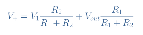
In the situation proposed in Figure 9, the differential input can be written Vin=V+-Vref=V+. Moreover, the voltage V+ can be written as a superposition of V1 and Vout thanks to Millman’s theorem:
The differential input is equal to zero when V1=-Vout(R1/R2). Since the output value can only be equal to VS or -VS, there are two values of V1 that can be seen as tipping points, we label them VT+ and VT- for “threshold”:
VT+=VS(R1/R2) is the upper threshold for which Vout=VS-→VS+
VT-=-VS(R1/R2) is the lower threshold for which Vout=VS+→VS-
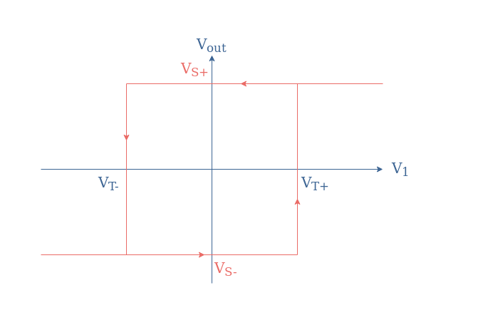
The input/output characteristic of a non-inverting Schmitt trigger is a hysteresis graph presented in Figure 10:
fig 10: Transfer characteristic of the non-inverting Schmitt trigger
Inverting trigger
We can as well consider the same positive feedback for an inverting configuration:
In this case, the differential input can be written Vin=Vout(R1/(R1+R2))-V1, the input voltage V1 that cancels the differential input is therefore given by V1=-Vout(R1/(R1+R2)).
Depending on the sign of Vout, two thresholds specific to the inverting configuration can be defined:
VT+=-VS(R1/(R1+R2))
VT-=+VS(R1/(R1+R2))
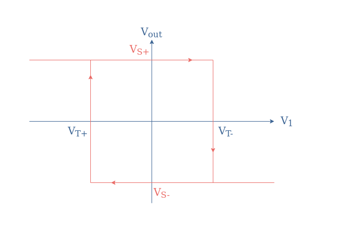
The associated hysteresis plot for the inverting Schmitt trigger is given in Figure 12:
fig 12: Transfer characteristic of the inverting Schmitt trigger
Applications
Schmitt triggers and comparators in general, as we briefly presented in Figure 8 are mainly used for the conversion of analogic signals to digital signals.
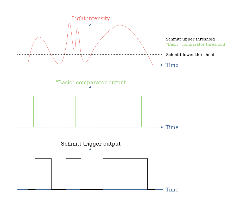
However, “basic” comparators present the disadvantage of being triggered by background noise. One of the very appreciated properties of Schmitt triggers is their noise immunity, which means that the comparator will switch between the low and high output states only when the input is effectively triggering it. Moreover, since the high output state is triggered by the upper threshold and the low output state by the low threshold, Schmit triggers usually add a delay in comparison with “basic comparators”.
When considering again Figure 8, we could imagine that during the second global light variation, the two peaks can be related to some noise (coming from the user for example).
Thanks to the hysteresis that can be achieved with a Schmitt trigger, if the lower threshold is set below the minimum noise level, the background noise does not trigger the comparator:
fig 13: Comparison of a “basic” comparator and a Schmitt trigger for level detection application
Conclusion
Comparators are operational amplifiers that are intentionally designed to work in open-loop or with positive feedback, which is both unstable and non-linear modes. Their output can only be equal to two different values, which correspond approximately to the power supply voltages. The output, or saturating voltages, depending on the input supplied. This input is being compared to a reference voltage which sets the threshold of the comparator.
In the second section, we have seen that the threshold voltage can be modified by adding a simple voltage divider circuit to the inverting branch of the op-amp. Basic comparators work in open-loop and present only one threshold, which makes them simple to design and with a fast response.
The third section focuses on Schmitt triggers which present the advantage to not be triggered by background noise, such as basic comparator do. Schmitt triggers do not work in open-loop configuration but instead with positive feedback to their non-inverting input. It allows them to have two threshold levels (high and low), as a consequence, their transfer characteristic is a hysteresis.
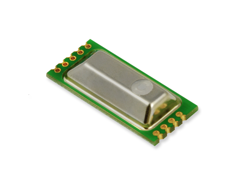
The EE895 sensor module is ideal for use in climate measuring devices. Pressure and temperature compensation ensure a high CO2 measuring accuracy.
The new EE895 sensor module from E+E Elektronik measures CO2, temperature and ambient pressure. The small 3-in-1 module is an ideal choice for measuring instruments used for ventilation and climate control, in building automation or for process control. Due to its low power consumption, the module is also suitable for battery-operated devices such as hand-held meters, data loggers or wireless transmitters. The temperature and pressure compensation ensures high CO2 measurement accuracy under changing environmental conditions.
A Single Module – 3 Measurands
Additionally to CO2 concentration up to 10 000 ppm the EE895 module measures also the temperature and ambient pressure. The pressure and temperature compensation with on-board sensors minimizes the environmental influences onto the CO2 measurement. Thus the module offers a constantly high CO2 measurement accuracy, independent of altitude or changing ambient conditions.
Long-Term Stable CO2 Measurement Principle
The dual wavelength NDIR CO2 measuring principle with auto-calibration ensures long-term stable measurements, as it automatically compensates for aging effects and is particularly resistant to contamination. The factory multi-point CO2 and temperature adjustment procedure leads to an excellent CO2 measurement accuracy over the entire temperature working range of -40…60 °C (-40…140 °F).
Easy Design-In
The measured data for CO2, temperature and pressure is available on the I2C or UART interface. The very small dimensions of only 35 mm x 15 mm x 7 mm (1.38″ x 0.6″ x 0.27″) and various mounting options facilitate the design-in of the sensor module.
Flexibly Configurable
The EE895 module can be flexibly configured via the digital interface. The CO2 measurement interval can be set according to the application and the power requirements.
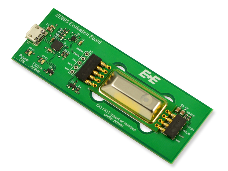
Evaluation Board for Testing on a PC
With the separately available EE895 Evaluation Board, the sensor module can be tested on a PC. The free evaluation software displays the measurement data in graphical form and allows the user to set the sampling rate and the measurement units for temperature and pressure. For further processing, the data can be saved as .CSV file.
Texas Instruments’ buffer features stuck bus recovery
Texas Instruments’ TCA4307 is a hot-swappable I2C bus buffer that supports I/O card insertion into a live backplane without corruption of the data and clock lines. Control circuitry prevents the backplane-side I2C lines (in) from being connected to the card-side I2C lines (out) until a stop command or bus idle condition occurs on the backplane without bus contention on the card. When the connection is made, this device provides bidirectional buffering, keeping the backplane and card capacitances isolated. During insertion, the SDA and SCL lines are pre-charged to 1 V to minimize the current required to charge the parasitic capacitance of the device.
The TCA4307 has stuck bus recovery, which automatically disconnects the bus if it detects either SDAOUT or SCLOUT are low for about 40 ms. Once the bus is disconnected, the device automatically generates up to 16 pulses on SCLOUT to attempt to reset the device which is holding the bus low. When the I2C bus is idle, the TCA4307 can be put into shutdown mode by setting the EN-pin low, reducing power consumption. When EN is pulled high, the TCA4307 resumes normal operation. This buffer includes an open-drain READY output pin, which indicates that the backplane and card sides are connected. When READY is high, the SDAIN and SCLIN are connected to SDAOUT and SCLOUT. When the two sides are disconnected, READY is low.
Supports bidirectional data transfer of I2C bus signals
Operating power supply voltage range: 2.3 V to 5.5 V
Ambient air temperature range (TA): -40°C to +125°C
Stuck bus recovery featuring automatic bus recovery
1 V pre-charge on all SDA and SCL lines prevents corruption during live insertion
Accommodates standard-mode and fast-mode I2C devices
Supports clock stretching, arbitration, and synchronization
Water Contact Indicator Tape from 3M™ changes color with water contact without performance degradation in high humidity exposure
3M™ Water Contact Indicator Tape is a tape that changes color from white to red upon contact with water. It is designed to withstand heat and humidity aging without giving water indications. The tape permanently changes from white to red upon direct water contact. In electronic products ranging from mobile phones, 2-way radios, video cameras, laptops, and Li-MH batteries/chargers to electrical box enclosures, users will have clear evidence of water contact without false identification from high humidity.
Highly absorbent, paper backing to transport water to show indication
Does not falsely indicate water contact in high humidity exposures
Performance not degraded by high humidity exposure
Printable top layer by thermal transfer, flexographic, or screen-printing methods
Easily die cuttable with rotary die-cutting process
Very high bond strength adhesive to most surfaces, including low surface energy plastics
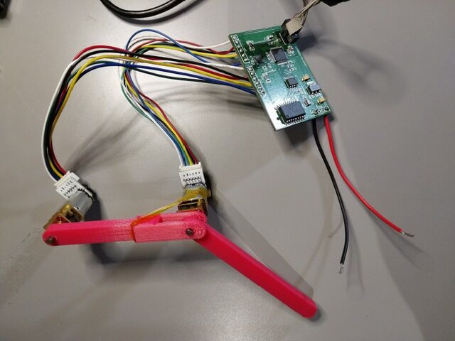
Jake Wachlin has posted on Hackaday a CANControlled Dual Closed-Loop Motor Controller. CAN is an acronym for Controller Area Network. This is a robotic vehicle bus standard designed to enable microcontrollers and devices to communicate with each other’s applications without a host computer. This mechanism is implemented in the CAN controlled dual closed-loop motor controller. This controlled dual closed-loop motor controller can be used for a SCARA robot, control a leg of a robot, and versatile if needed for any motor control. About the project, Jake says “This project aims to develop a low-cost design which can be used for closed-loop control of two micro-gear motors. The current to the motors will also be monitored for current limiting and possible impedance control applications. It can be interfaced over CAN bus, ensuring robustness and scalability in robotics applications.”
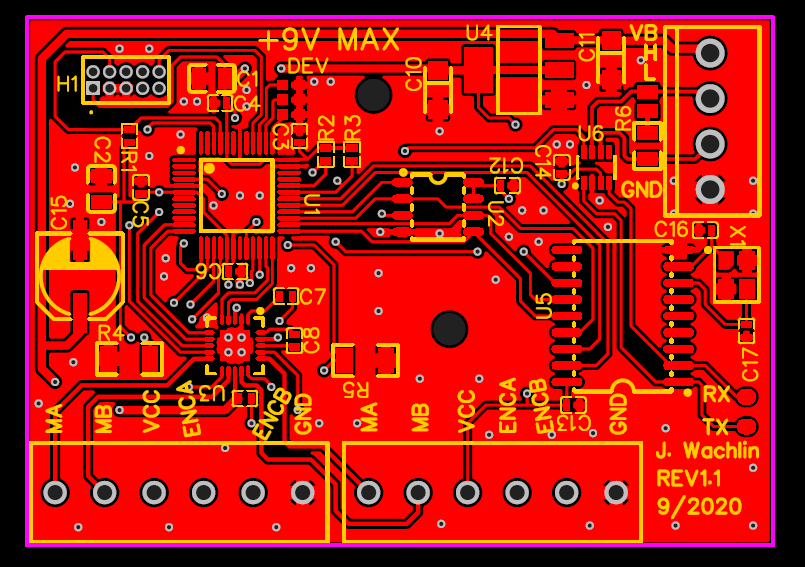
The PCB Layout
During the course of the project, CAN interface didn’t work with the V1.0 dual controller, however, Jake says that a V1.1 update should improve the workings of the controller. Also, the use of JLCPCB as an assembly service and EasyEDA for its clean interface is part of the changes made amongst the following :
Add a 16MHz crystal to the MCP2515 to fix the CAN issue
Add pads at logic level CAN TX/RX for debugging support
Label all external connections on the silkscreen
Label maximum input voltage
Add optional CAN 120 Ohm termination resistor with a solder jumper
Add 3-bit device numbering with solder jumpers to address devices without firmware changes
The first version just used 0.1″ pitch through holes for the motor and power/CAN connections. On V1.1 I chose actual screw terminal connections so wires don’t need to be soldered permanently in
Add holes that can be used for mounting
Add bulk capacitance for the motor controller (doesn’t seem strictly necessary, but not a bad idea to have).
The assembly service supports a limited number of components and only single-sided SMD parts so are preferable if the assembling can be done personally.
These dual motor controllers are meant to be peripherals on a larger network. They receive higher-level commands from some external device over CAN, and handle the low-level motor control, therefore building a simple main controller is advisable. The main requirements are an attitude sensor and sufficient computational capability to theoretically run complex walking gait controllers. The ESP32 with 2 cores at 240MHz is used because of its computational capability to run fairly complex control schemes that have a built-in CAN controller. It also supports wireless connectivity so commands can be sent remotely.
With the project now able to control two motors well, and much of the supporting code for more complicated use cases written, the next step is to set up the communication between devices. For this, the Controller Area Network (CAN) bus is used. Originally developed for automotive use, CAN allows for relatively high-speed, robust, and long-range multi-master communication. It uses two wires which are differentially driven by a dedicated transceiver. Preferably use the TCAN334. While some microcontrollers have a CAN controller built-in, the ATSAMD21 does not, so use the ubiquitous MCP2515. The MCP2515 is commonly used in all sorts of low-cost hobbyist (and serious commercial) CAN applications. It has an SPI interface to the ATSAMD21.
More information about the controller can be found on Jake’s project page on Hackaday.
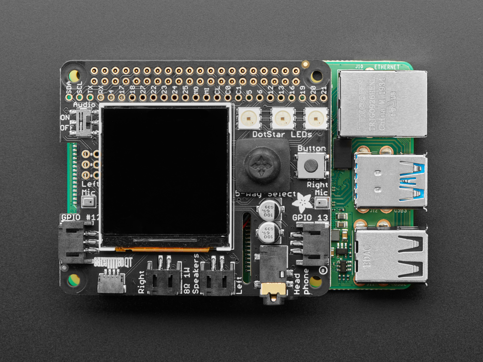
Think about what would be useful when developing your machine learning projects for the Raspberry Pi, maybe a camera, a display, some input and output sound capabilities or even an easy means to easily inject the results of your algorithms into servo motors or other devices. Look no further, as the BrainCraft HAT gives you everything you need to kickstart your machine learning on the Raspberry Pi!
The BrainCraft HAT is Adafruit’s take on how you would like to make machine learning projects for the Raspberry Pi, making it easy for you on the development stage. Their inspiration came when they picked up some popular projects on TensorFlow and realized what would be handy to have in each of them. For example, in computer vision projects, how annoying it was not to have a visual representation of what is happening. There is also a slot for a camera, a joystick, buttons, microphones for your audio recognition projects (which can be mechanically powered off, something Alexa and other home assistants should take into consideration) and some extra connectors where you can easily plug relays, servo motors and other electronics, which is something you do not see a lot and extremely useful, bringing the gap between actuators and machine learning even closer. Lastly, as this is a HAT, you can still access you Raspberry Pi pins.
Stereo microphone input (with an On/Off switch that completely disables the audio codec);
2x 3-Pin JST STEMMA connectors on PWM pins + 1x STEMMA QT plug-and-play I2C port (can be used to connect objects such as heat sensitive cameras);
5-Way Joystick + Button for user interface and control;
3x RGB DotStar LED’s for colorful feedback;
Controllable mini fan on the bottom to cool your Raspberry Pi.
The HAT’s performance is very acceptable, by looking at the introductory video on their website. They showcased an object identification project directly on the Raspberry Pi 4, packed with the TensorFlow Lite, while displaying video from the camera on the display and everything worked seamlessly. Interestingly, the performance only started to dip when the fan was turned off, typical of the Raspberry Pi 4.
Regarding the state of the BrainCraft HAT, it was just released and almost immediately stocked out, showing it already is taking off in the maker industry! Don’t worry, you can get notified via email when it gets stocked back. At a price of $39.95, you get a lot of value.
What do you think? Is it something you’ll consider pick up? I certainly think is worth your time.