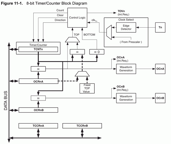
I’ve written a few software UARTs for AVR MCUs. All of them have bit-banged the output, using cycle-counted assembler busy loops to time the output of each bit. The code requires interrupts to be disabled to ensure accurate timing between bits. This makes it impossible to receive data at the same time as it is being transmitted, and therefore the bit-banged implementations have been half-duplex. By using the waveform generator of the timer/counter in many AVR MCUs, I’ve found a way to implement a full-duplex UART, which can simultaneously send and receive at up to 115kbps when the MCU is clocked at 8Mhz.
The voltage signal applied to an op-amp can either be supplied to its non-inverting input (+) or the inverting input (-). These different configurations are simply known as a non-inverting op-amp, and inverting op-amp. In this tutorial, we focus on the non-inverting configuration and present its details.
An overview of the non-inverting op-amp will be given in the first section through the concept of the ideal amplifier.
In the second section, real non-inverting configurations are discussed, we demonstrate the equations describing the gain and the input/output impedances.
Finally, examples of circuits based on the non-inverting configurations are given in the last section.
Ideal non-inverting op-amp
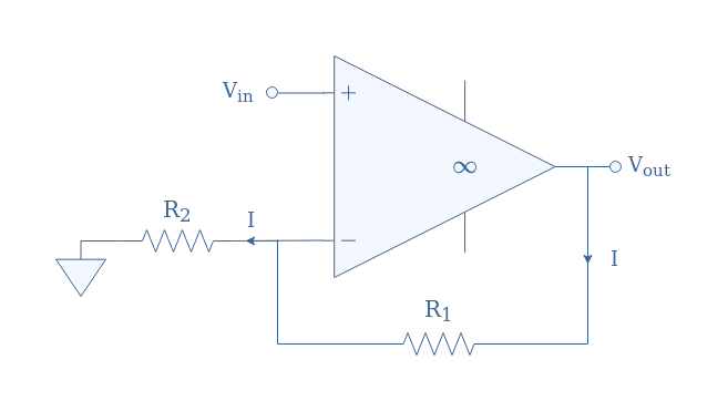
The goal of this section is to properly demonstrate and explain the ideal characteristics of the non-inverting configuration such as its input/output impedance and gain. The circuit representation of an ideal non-inverting op-amp is given in Figure 1 below.
Note that the symbol “∞” highlights the fact that the op-amp is here to be considered ideal. We highly recommend the reader to refer to the tutorial Op-amp basics for this section.
fig 1: Ideal non-inverting op-amp circuit
In this ideal model, the input impedance defined by the contribution of the resistance linking the inverting and non-inverting inputs (Ri in Figure 3) and the resistors R1 and R2, is infinite. Moreover, for an ideal circuit, Ri is supposed to be infinite, as a consequence, no currents can enter the op-amp through any input because of the presence of an open circuit.
This observation can also be summarized by saying that the node interconnecting the inverting input and resistances R1 and R2 is a virtual short. For this same reason, all the feedback current across R1 (I) is also found across R2.
For the ideal model, the equality V+=V–=Vin is assured by the fact that the differential signal V+-V– can only be equal to 0 in order to produce a finite output Vout when multiplied by an infinite open-loop gain.
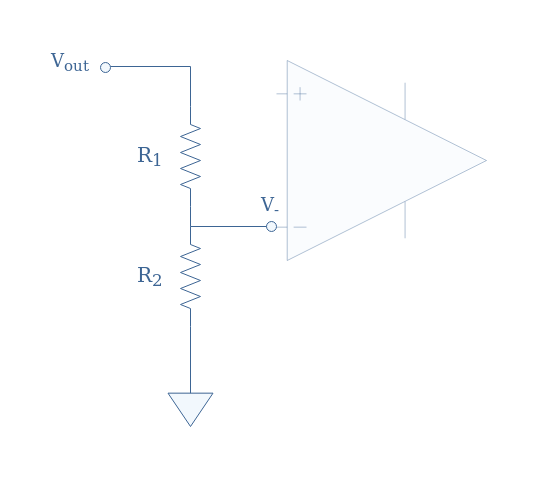
We can see the branches connected to the inverting input acting as a voltage divider circuit:
fig 2: Inverting branches seen as a voltage divider circuit
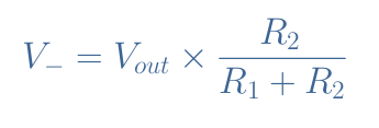
According to the voltage divider formula, we can express the inverting voltage V– as a function of the output voltage and the resistances:
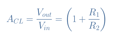
Since V–=Vin, after some simplification, we prove the expression of the gain in closed-loop ACL of an ideal non-inverting configuration:
eq 2: Closed-loop gain of an ideal non-inverting op-amp
We can note that the ideal gain presented in Equation 2 is strictly positive and higher than 1, meaning that the output signal is amplified and in phase with the input signal.
Real non-inverting op-amp
In a real op-amp circuit, the input (Zin) and output (Zout) impedances are not idealized to be equal to respectively +∞ and 0 Ω. Instead, the input impedance has a high but finite value, the output impedance has a low but non-zero value.
The non-inverting configuration still remains the same as the one presented in Figure 1.
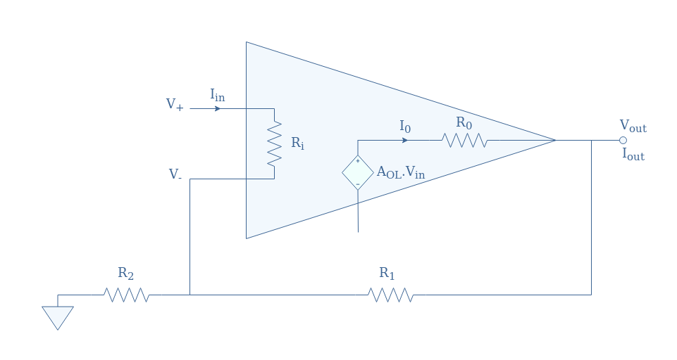
fig 3: Internal equivalent circuitry of a real op-amp
Note that Ri and Ro can be described to be respectively the input and output impedances of the op-amp without any feedback loop (open-loop configuration).
Closed-loop gain
For a non-inverting configuration, Equation 1 still applies for V– , moreover, we have V+=Vin. However, since a low current can flow from the non-inverting input to the inverting input, the voltages are not equal anymore: V+≠V–.
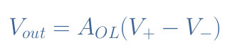
We also need to remind that the inputs V+ and V– are linked with the output through the open-loop gain formula:
eq 3: Open-loop gain formula
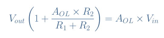
The equations for V+ and V– can be injected in Equation 3. After regrouping the terms “Vout” on one side of the equation and the terms “Vin” on the other, we get:
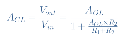
Finally, the closed-loop gain ACL for a real non-inverting configuration is given by Equation 4:
eq 4: Closed-loop gain of a real non-inverting configuration
For a real configuration, the gain not only depends on the resistor values but also on the open-loop gain
It is interesting to note that if we consider the op-amp to be ideal (AOL→+∞), the denominator is simplified to one term: AOLR2/(R1+R2). As a consequence, Equation 4 is simplified back to Equation 2.
Output impedance
We start by assuming the equality of the currents across the resistances: IR1=IR2. Even if for real op-amps, a small leaking current enters the inverting input, it is several orders of magnitude smaller than the feedback current.
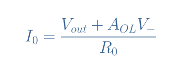
The current I0 across R0 (see Figure 3) can be expressed as a function of the voltage drop across R0 and the same value of the impedance R0:
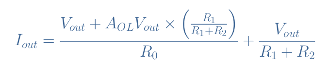
Since V– is described by Equation 1, the output current Iout can be expressed as the sum of I0 and the current flowing in the feedback branch given by Vout/(R1+R2):
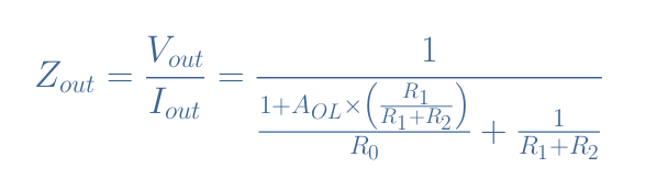
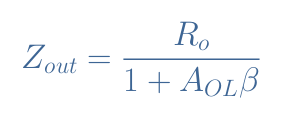
Finally, after rearranging the equation to obtain the ratio Zout=Vout/Iout, we can write the expression of the output impedance for a real non-inverting configuration:
eq 5: Expression of the output impedance for a real non-inverting configuration
We can note that in the case of an ideal op-amp, that is to say when AOL→+∞, we observe indeed Zout→0.
A simplified version for the expression of Zout is given by the following Equation 6:
eq 6: Simplified expression of the output impedance for a real non-inverting configuration
The term β is known as the feedback factor and is given by the ratio R1/(R1+R2). With that simplified version, we can still see that Zout→0 for an ideal op-amp situation.
Input impedance
The input impedance of a non-inverting configuration can be defined by the ratio V+/Iin (see Figure 3). For the input loop, we can write Kirchoff’s voltage law such as V+-Vin+IR2R2=0 with IR2 being the current across the resistor R2.
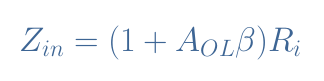
It can be shown that the expression of the input impedance can also be written as a function of the feedback factor:
eq 7: Expression of the input impedance for a real non-inverting configuration
Again, when the ideal situation is satisfied (AOL→+∞) we find that Zin→+∞ such as specified in the first section.
Non-inverting op-amp examples
Buffer circuits
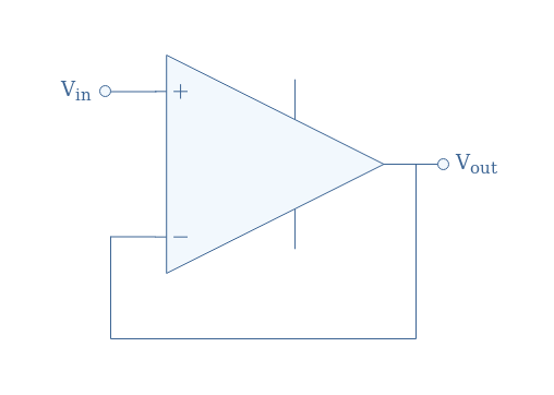
The most simple designs for non-inverting configurations are buffers, which have been described in the previous tutorial Op-amp Building Blocks. In this configuration, R1=0 and R2→+∞ as we can present in Figure 4 below:
fig 4: The buffer circuit
This buffer (or voltage follower) has a unity gain and does not invert the output, meaning that Vout=Vin. Its high input impedance and low output impedance are very useful to establish a load match between circuits and make the buffer to act as an ideal voltage source.
Example
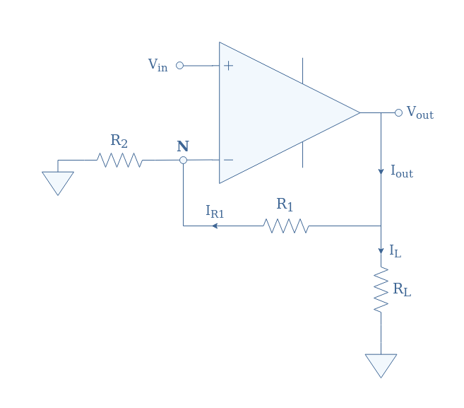
We consider a real non-inverting configuration circuit given in Figure5:
fig 5: Example of real non-inverting configuration
The resistors, input value, and gain in open-loop are given such as:
R1=10 kΩ
R2=2 kΩ
RL=1 kΩ
Vin=1 V
AOL=105
First of all, we can compute the value of the closed-loop gain ACL. By using Equation 4 we obtain ACL=5.99 while Equation 2 gives ACL=6. We can remark that both values are very similar since AOL is high. Typical values of AOL for real op-amps range between 2×10⁴and 2×10⁵, which is high enough to always consider Equation 2 valid.
From this value, we can simply say that the output voltage is given by Vout=ACL×Vin= 6 V.
The currents IR1 (across R1) and IR2 (across R2) are approximately equal if we consider the leaking current in the inverting input to be much lower than the feedback current. Due to the virtual short existing at the node N, VN=Vin, and therefore we have IR1=IR2=Vin/R2=0.5 mA.
Since the current IL through the output load is given by Vout/RL=6 mA, we can determine the output current thanks to Kirchoff’s current law: Iout=IL+IR1=6.5 mA.
Finally, we can also specify the output impedance to be Zout=Vout/Iout=920 Ω.
Conclusion
When the input signal is supplied to the pin “+”, the op-amp is said to be in a non-inverting configuration. The design and main properties of this configuration are presented in the first section that presents its ideal model.
In the second section, the real non-inverting op-amps are presented. Due to the parasitic phenomena that are intrinsic to their design, their properties change, the expression of the closed-loop gain, input, and output impedances are different. However, the simplified version of these formulas that describe the ideal model can indeed be recovered when we set the open-loop gain to be infinite.
Examples of real configurations are shown in the last section, we present how to calculate the main characteristics of a configuration with the knowledge of the resistors value and input voltage.
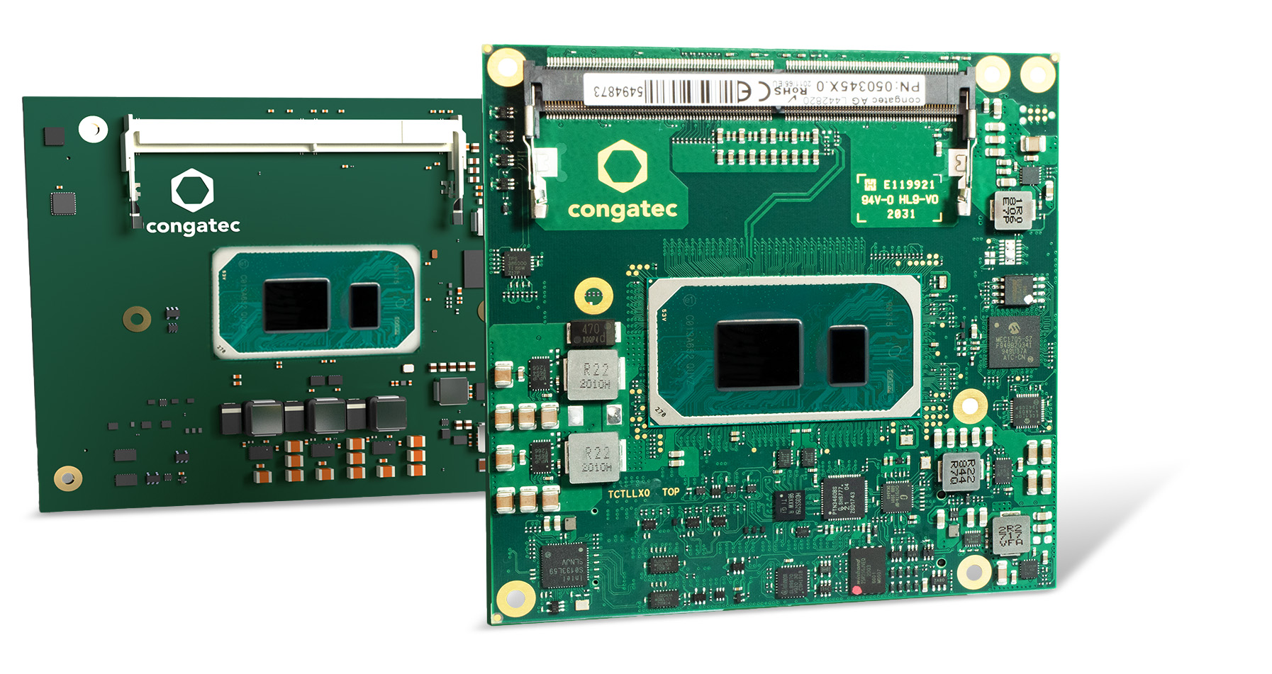
congatec fuels launch of 11th Gen Intel® Core™ processors with two great new design options
In parallel with the 11th Gen Intel® Core™ processor launch (code named “Tiger Lake”), congatec – a leading vendor of embedded computing technology – announces the availability of both its first COM-HPC Client size A module and a next generation COM Express Compact Computer-on-Module. This provides engineers the choice to further scale the performance of their existing systems or develop the next generation of products utilizing COM-HPC’s broader array of interfaces. OEMs will benefit from the substantial performance improvements as well as communication enhancements that the new modules based on 11th Gen Intel Core processors deliver to the high-end computing sector. Typical applications can be found in many high-end solutions, from embedded systems and edge computing nodes to network hubs, and local fog data centers to core network appliances, as well as ruggedized central cloud data centers for critical government applications.
“congatec’s modules based on the 11th Gen Intel Core processors feature high-performance CPU/GPU compute with integrated AI acceleration for critical applications that demand high-speed processing, and computer vision,” explains Gerhard Edi, CTO at congatec. The highlights of the 11th Gen Intel Core processors provide a massive CPU performance boost, fast DDR4 memory, expansive PCIe Gen4 and USB 4.0 bandwidth. These performance enhancements are complemented by features that are critical for communication connected edge computers such as congatec’s support for hypervisor technologies e.g. from Real-Time Systems. All this comes in a powerful and energy-efficient package leveraging Intel’s SuperFin technology delivering increased power savings, physical density and providing even more compute power for given thermal envelopes.
The benefits of choice
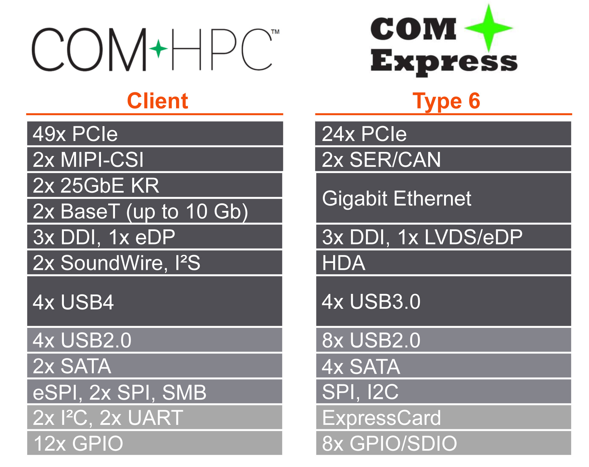
“For the first time, design engineers now have the choice to go either with COM Express or COM-HPC. Each provide unique benefits for example, we have an improved next-gen connector for COM Express that is expected to offer better bandwidth capacities compared to what was available in the past. This is essential information for engineers thinking about utilizing the high bandwidth interfaces such as PCIe Gen 4. Engineers choosing COM-HPC will benefit from by far more high-speed interfaces delivered over 800 signal pins in total. This is almost twice as many pins as COM Express Type 6 modules deliver with 440 pins,” explains Andreas Bergbauer, Product Line Manager at congatec.
To help engineers make the best choice, congatec provides engineering support and is creating a COM Express and COM-HPC design decision guide and a whitepaper, which will be available on congatec’s 11th Gen Intel Core processors page.
Even more innovations and benefits
It is important to mention that besides PCIe Gen 4, the new congatec Computer-on-Modules with low-power 11th Gen Intel Core processors also offer USB 4.0, which is fundamentally based on Intel’s Thunderbolt technology. USB 4.0 supports amazing data transfer rates of up to 40 Gbit/s and tunneling of PCIe 4.0 as well as DP-Alt mode supporting video signals of up to 8k resolution with 10-bit HDR at 60 Hz.
The feature set in detail
The COM-HPC Client size A module conga-HPC/cTLU as well as the COM Express Compact conga-TC570 will become available with the 11th Gen Intel Core processors. Both modules are the first to support PCIe x4 in Gen 4 quality to connect external peripherals with massive bandwidth. In addition, designers can leverage 8x PCIe Gen 3.0 x1 lanes. Where the COM-HPC module offers latest 2x USB 4.0 and 2x USB 3.2 Gen 2 and 8x USB 2.0, the COM Express module offers 4x USB 3.2 Gen 2 and 8x USB 2.0 in compliance to the PICMG specification. Sound is provided via I2S, SoundWire by COM-HPC, and HDA by COM Express modules. Comprehensive board support packages are provided for all leading OS’s like Linux, Windows and Chrome, as well as hypervisor support from Real‑Time Systems.
Further information about congatec’s new modules based on 11th Gen Intel Core processors can be found on the main landing page www.congatec.com/11th-gen-intel-core/
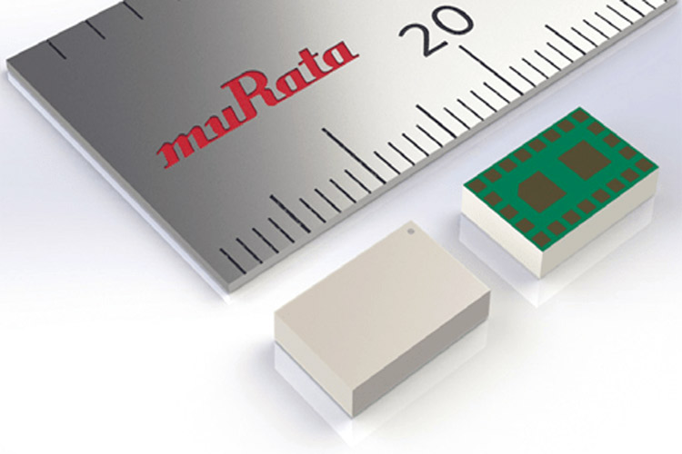
Murata Electronics today announced the availability of the Type 1RM ultra-small Medical Implant Communication System (MICS) band radio module. The LBAA0PC1RMH298 is designed for use in devices with data-intensive wireless capabilities that are used to diagnose, monitor, report, and provide warnings in support of human life. Typical applications include insulin, drug, and baclofen pumps as well as arrhythmia and bladder monitors.
Measuring just 8.6 x 5.6 x 1.7mm, this module is one of the smallest and most highly integrated solutions available. What differentiates the LBAA0PC1RMH298 from alternative products is Murata’s proprietary technique that discretely bundles several technological components and ICs into one miniatured package. The result is an advanced module that delivers a communication range up to two meters, an ultra-low current consumption of 0.2uA Sleep State, and a 128 kbps data rate.
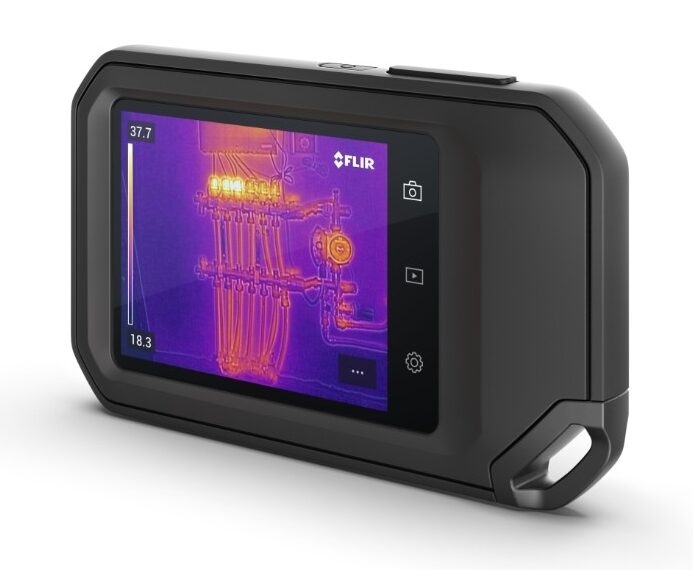
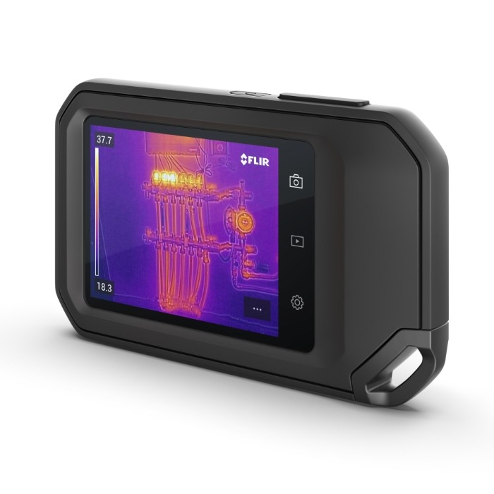
Flir C5 brings all the best from older C3 but features several major improvements. The main are 4x higher IR resolution (160x120px) and the WiFi + Bluetooth connectivity. Simply put, the ideal thermal camera for the fieldwork.
If you liked the popular pocket-sized industrial thermal cameras Flir C2 and C3 Series, you would certainly love the new C5.
Main features:
4x higher IR resolution (160x120px) comparing to C3 model
Instant backup of your images to Flir Image Cloud Ignite (FREE 1 GB Storage, software available on PC and mobile).
Automatic or Manual setting of level and span of temperatures of your measuring object? All available at one click.
3,5” LCD screen (+36% more area in comparison to C3)
5MPx visual camera
Double the operating battery life up to 4 hrs
Possibility to input notes and edit in the gallery, directly in the camera
Built-in tripod mount
IP rating 54
Measuring range -20 to +400°C
Naturally, even the Flir C5 features MSX function for overlaying images in an infrared and visible spectrum for easier identification.
It’s worth saying that in contrast with some cheaper types of infrared cameras on the market, stored images are fully thermometric, i.e. the stored image file carries information about the temperature of every pixel measured with IR camera with the possibility to post-process in Flir tools SW.
With Flir C5, you can edit images and use the Cloud feature to create and share reports directly from the measurement point much faster and easier. In many cases, you do not have to sit by the computer, but create a report from the measurement directly in the field.
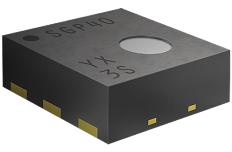
Sensirion has introduced a new SGP40 VOC (Volatile Organic Compound) sensor for maintaining indoor air quality in modern buildings. VOCs are the most responsible components for bad air quality in the modern buildings, this needs to be monitored and necessary steps should be taken to maintain the air quality. The new broadband VOC, SGP40 can identify VOC pollution source and allows the user to take necessary action when they are built into an air quality monitor.
With an integrated CMOSens sensor system on a single chip based on a metal oxide sensor provides a humidity compensated indoor air quality signal via a digital I2C interface. With outstanding long term stability of sensing and response time, the SGP40 provides low power consumption for battery-driven applications.
The VOC algorithm analyses the VOC events from the SGP40 and store them in a VOC index that qualifies the VOC events relative to each sensor’s average indoor environment. The VOC index states that to what extent the indoor air quality has deteriorated or improved to the average VOC environment, using this data users can gradually control the fan of an air treatment device or they can use it as feedback on their daily activity profile. Both SGP40 and the evaluation kit are available through the Sensirion’s distribution network.
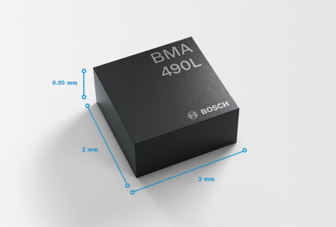
Bosch Sensortec’s high-performance longevity triaxial accelerometer features extended availability of up to ten years
Bosch Sensortec’s BMA490L is a high-performance longevity triaxial accelerometer with extended availability of up to ten years. BMA490L is designed to cater the long life cycles of mobile and stationary industrial applications such as robots, white goods and other industrial IoT (IIoT) applications. The BMA490L is a triaxial, low-g acceleration sensor with digital interfaces, aiming for various stationary and mobile industrial applications.
Applications
Industrial IoT (IIoT), e.g. predictive maintenance, vibration monitoring
Logistics, e.g. asset tracking
Agricultural and industrial robots, e.g. orientation detection, tilt detection
White goods and home appliances, e.g. vibration monitoring, power management
Power tools, e.g. power management, device level detection
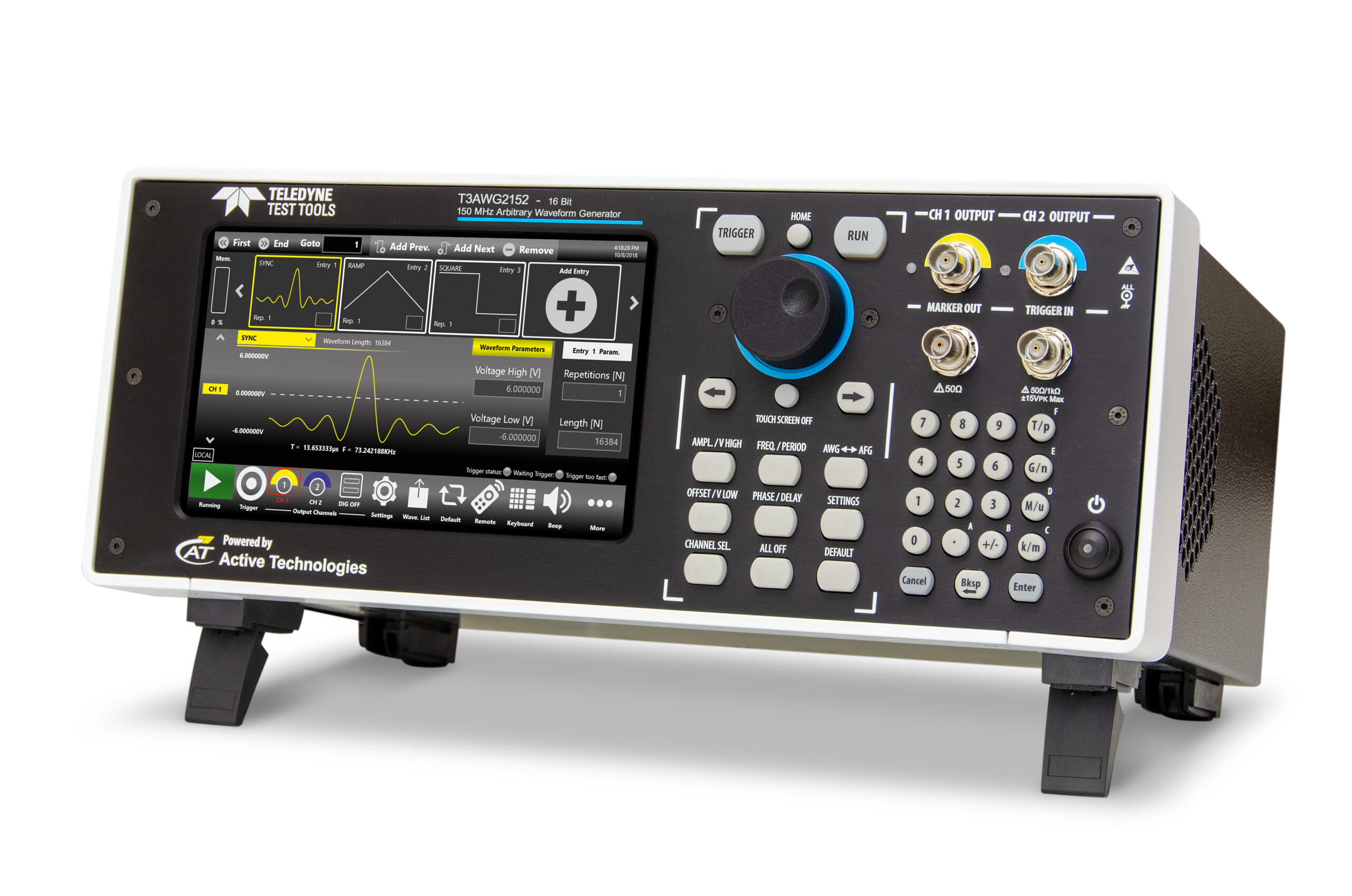
The T3AWG2152-D’s analog/digital synchronized output represents a valuable tool to simulate, troubleshoot, or validate digital designs.
Saelig Company, Inc. has introduced the Teledyne LeCroy T3AWG2152/T3AWG2152-D Multifunctional 16-bit Arbitrary/Function Generators that are designed with innovative architecture and synchronized digital pattern generation.
The T3AWG2152 and T3AWG2152-D generators are multifunctional 150MHz arbitrary/sweep/function generators that combine multiple functions in a single instrument, including a two-channel function and arbitrary waveform generator with an eight-channel digital pattern generator (in the D version). These three different functionalities are based on an advanced Direct Digital Synthesis (DDS) technology which allows glitch-free on-the-fly changes of all parameters while preserving the selected waveform shapes. All controls and settings are available with touch/swipe gestures on the color LCD: change the channel, the carrier selection, access the modulation parameters, access the waveform gallery to import a signal at a glance, or use the virtual numeric keyboard to change parameters values.
The variable clock, true-arbitrary technology of the Arbitrary Waveform (AWG) / Digital Pattern Generator lets the user create complex signals of synchronized analog waveforms and digital patterns. Users can create signals in a sequence, or apply loops, jumps, and conditional branches. The analog/digital synchronized outputs represent a valuable tool to simulate, troubleshoot, or validate digital designs. Users can use the waveform sequencer to generate quite complex or very long signals with multiple waveform shapes. The AWG mode uses a variable or synchronized sample rate ‘True-Arb’ technology to suit applications requiring extremely high signal fidelity. The platform’s deep memory enables the capability to store numerous long waveforms.
16-bit vertical resolution
Up to 16,384 waveform entries in the sequencer
128Mpts arbitrary waveform memory on each channel (standard)
Output impedance 50 Ω and 5 Ω selectable
Application tasks for which this test instrument is especially suited include the Distortion Test for Automotive Ethernet 100Base-T1 and 1000-Base-T1Power and the Semiconductor Dynamic Behavior Test, made easier with the instrument’s versatile double-pulse test capability. Among the compliance tests specified for the Automotive Ethernet standard none is more complex to set up than the transmitter distortion test. Using the T3AWG2152, as well as a Teledyne LeCroy oscilloscope and the QualiPHY Compliance Manager, testing is greatly simplified. The T3AWG2152’s excellent Harmonic Distortion performance, combined with the output voltage amplitude range and the precise tuning of the delay and phase of the differential signal pairs, makes the T3AWG2152 a perfect tool for emulating the disturber signal, to assist in avoiding pitfalls encountered during the execution of the test.
The T3AWG2152/T3AWG2152-D can also quickly determine the dynamic behavior of power devices. The standard feature Double Pulse function required for testing MOSFETs and IGBTs is made simpler because the two pulses can have a different amplitudes, rise-times, fall-times, and widths.
The Teledyne LeCroy T3AWG2152/T3AWG2152-D Multifunctional 16-bit Arbitrary/Function Generators are available now from their authorized North American distributor Saelig Company, Inc. Fairport, NY.
Alibaba has provided more details on its first RISC-V-based product; A 16-core RISC-V processor called the XT 910.
As at the time of its release in July 2019, not much was said about the XuanTie 910 except that it was targeted towards the high-performance end to end 5G, AI, and autonomous driving applications. But during the virtual Hot Chips 2020 conference held recently, Alibaba gave more insight on the overview of the processor, how it stacks up to Arm’s Cortex-A73, and a glimpse of what they plan for down the road.
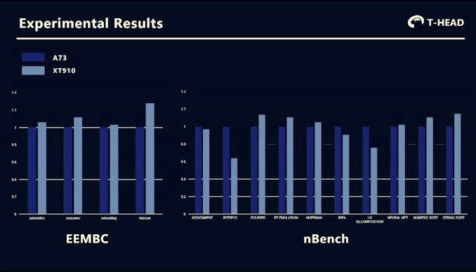
Alibaba claims the XT910 (XT stands for Xuantie, which is a heavy sword made using dark iron), is the most powerful RISC-V processor to date. The performance of the XT910 was compared to Cortex-A73 (Kirin 970) with the same L1 cache capacity, and the results showed that Alibaba chip outdistanced the Cortex-A73 in a number of the benchmark parameters. We are however not sure if the benchmarks included the RISC-V Turbo extension.
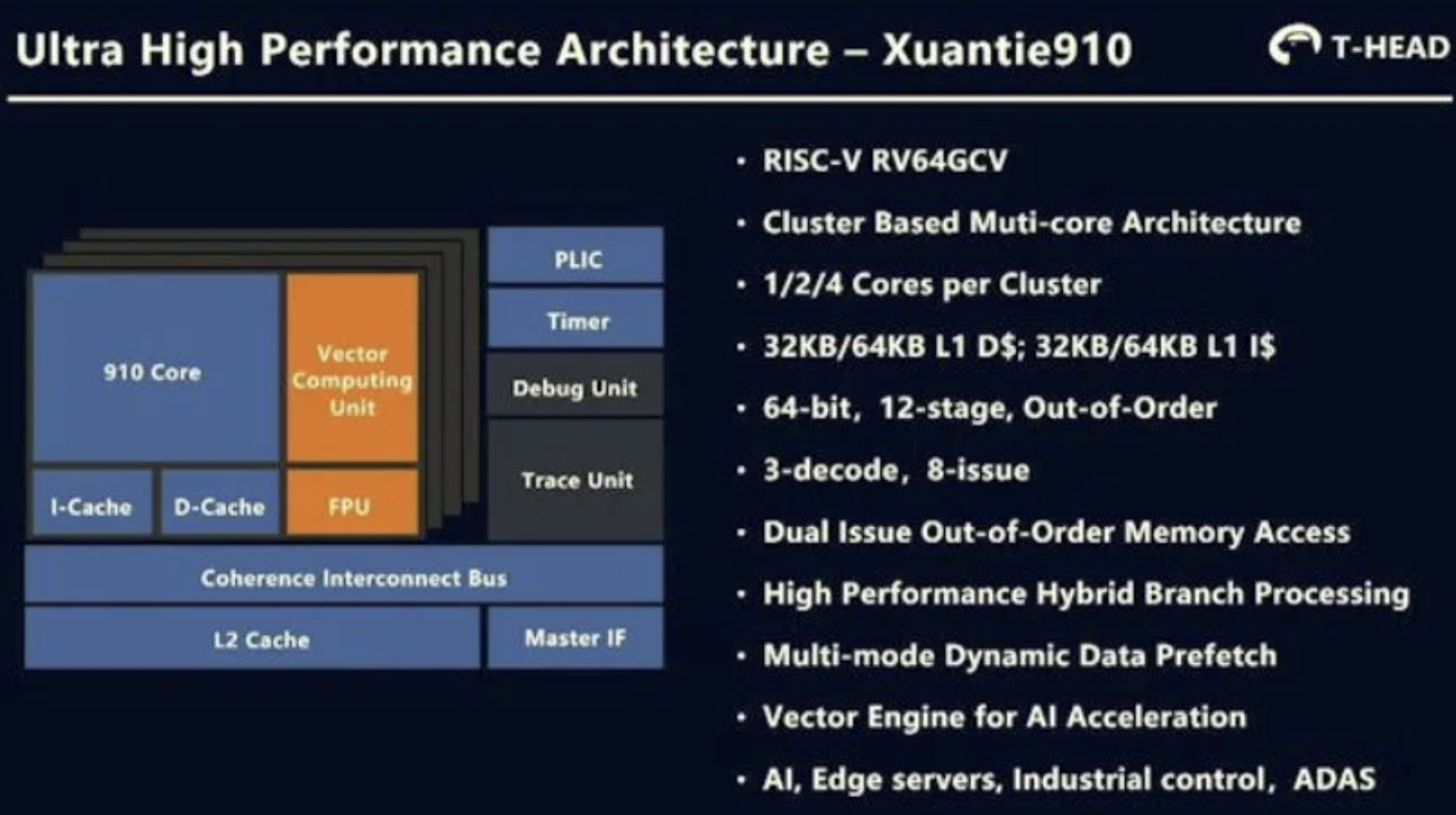
Some features and specifications of the XT910 processor include:
16x 64-bit RISC-V (RV64GCV) cores with a peak clock speed of 2.0GHz and 2.5GHz etched in 12 nm processes which include 16-bit instructions.
Supports RISC-V 0.7.1 Vector extension and custom Turbo extension
Up to Four clusters of four cores
32KB or 64KB instruction/data cache per core and up to 8MB L2 cache per cluster
Vector Computing Unit for AI acceleration
Sv39 MMU + 8/16 PMP
Clint + PLIC interrupt controller, and,
Support for unaligned memory data access
Yu Pu, edge product lead for T-Head semiconductor, the Alibaba organization that designed the chips said Alibaba is looking to make RISC-V the basis for its cloud and edge computing infrastructure. He admitted that the RISC-V is not “mature enough” in terms of technology and ecosystem”, but they are confident it holds a lot of potentials and wants to work with the open-source community to improve it.
XT910-vs-Arm-Cortex-A73 benchmark results
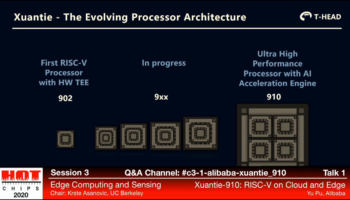
The company also revealed that the XT910 is the first in the line of what they plan to roll out as they have added a low power XT902 microcontroller core (Cortex-M0+ class) with hardware TEE to the league. Plans for others – including the XT903, XT905, XT907, and XT908 – that will come with different embedded performance and power levels, are also on top gear.
Like Google, a lot of cloud companies are beginning to show interest in the development of processors and microcontrollers that allows users to consume their services in unique ways. With the Google Coral Series and these new lines of Processors and microcontrollers from Alibaba, we are definitely in for a highly competitive high-performance computing future. [via www.cnx-software.com]
With the gKINO-V1000 small series, ICP Germany strengthens its product portfolio in the Mini-ITX board area by two AMD® based solutions with RyzenTM CPUs.
The gKINO-V1605B board is equipped with the quad-core processor V1605B with 3.6GHz clock frequency, whereas the gKINO-V1202B is equipped with the dual-core processor V1202B with 3.2GHz processor clock. Common to both is the RadeonTM VEGA HD7000 graphics. It supports a resolution of 4K (3840×2160) on its four display port outputs. DX11, UVD3, H.264, VC-1, MPEG-2, DivX®, Open CLTM, OpenGL 4.2 and soon Open GL4.3. gKINO-V1000 series can be equipped with a maximum of 64GB ECC memory on the two 260 pin SODIMM slots.
The gKINO-V1000 series offers on the IO-Shield besides the four DP interfaces, two RJ45 GbE, two RS-232, two USB2.0, two USB 3.2 Gen1 with 5Gb/s and audio with 6 Watt amplifier circuit. Furthermore, two RS-232 with Cctalk, four RS-232, two USB 2.0, SATA 3.0 and 8-bit GPIO are available on pin header. Expansion cards can be operated on the PCI Express x16 and the M.2 2242/2280 slot with PCIEe x2 and SATA signal. To secure the system, the boards can be delivered equipped with a TPM 2.0 Nuvoton NPCT750AAAYX. The boards also have an intrusion detection pin and watchdog functionality. Both versions work reliably in a temperature range from -10 °C to 70 °C.
Upon customer request, ICP can also supply the two gKINO-V1000 boards as a bundle with processor, industrial RAM and storage media.
Specifications
Mini-ITX Form Factor
AMD® RyzenTM V1000 Embedded CPU
Max. 64GB DDR4 SO-DIMM memory with ECC support
Quadruple/4-fold 4K Display Support
AMD RadeonTM GPU VEGA Graphics
1x M.2 2280, 1x PCIe x16
GbE Ethernet, USB3.2, DP, RS-232
Intrusion Detection, TPM, Cctalk, Watchdog
Applications
Industrial PC Systems
Compact PC Systems
Image and video processing
Panel PC and embedded systems
Gaming
The gKINO-V1000 series appears to be available now from ICP Germany. More information may be found in ICP’s announcement.