Saelig Announces The PF08H1 Facial Temperature Screening Kiosk

This slim, plug and play, free-standing thermal screening system offers a touch-less way to protect environments from risks of illness and viruses via advanced thermal imaging, providing instant body temperature measurements with an accuracy of +/-0.5°F

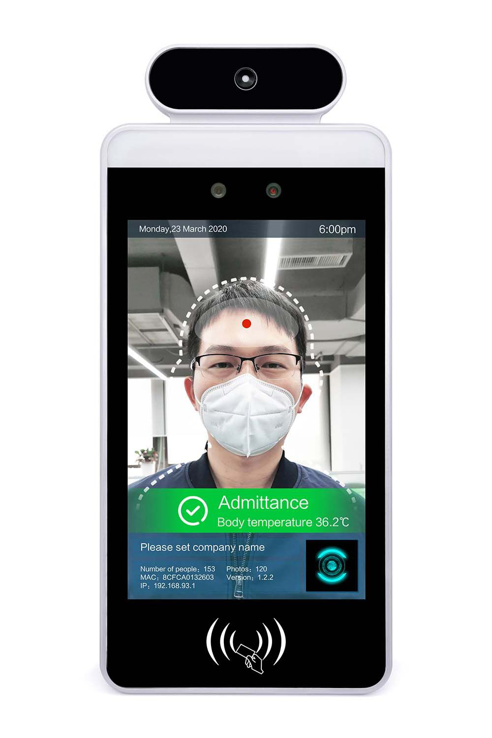
Saelig Company, Inc. has introduced the PF08H1 Facial Temperature Screening Kiosk – an easy-to-use, self-contained personnel temperature screening device that scans in under 3 seconds, thus allowing or denying entry. Using Heimann sensor technology from Germany, a global leader in thermal imaging technology, the PF08H1 Thermal Guard system detects face temperature with an accuracy of ±0.5degF. This touchless, plug and play standalone system does not require any operator participation, with network connection optional. The 11.6″ x 5.2″ x 1″ Thermal Guard, mounted on a 40” sturdy floor-stand, features an 8”high-resolution LCD display, and provides individual body temperature measurements. It can trigger alerts when readings are higher than normal. With face shape recognition technology, the device can also detect individuals with or without protective facial masks. This provides an unobtrusive way of scanning personnel and makes working environments safer. Access can be denied if no mask is detected. The system can be set up to send an alert via email and/or text when a user has a high temperature or isn’t wearing a mask. It can use facial recognition to deny access to strangers, and also time-stamp employee arrival. The device comes with facial biometric recognition technology using Dual Wide Angle Binocular Cameras. It can support various RFID card readers to allow card access identification.

The high-quality infrared thermal sensor detects body temperature from 32 multi-points on the face with an accuracy of ± 0.5degF. The large, high-resolution LCD can be used as a real-time surveillance visual display. The device can be integrated with turnstiles and magnetic lock doors to provide automated and contactless access. This avoids the unpleasant experience of having an employee or security guard pointing handheld devices at guests, and allows business owners to protect their establishment with minimal distraction & effort. This product is not a medical device and is not intended to be used for diagnostic purposes.

  • Instant – scan each person in under 3 seconds – no calibration needed.
  • Accurate – 32 averaged facial multi-points detect body temperature with an accuracy of ± 0.5ºF.
  • Easy to Use – simple plug and play with a slim, modern design.
  • Contactless – touch-less to the user and does not require any participation from an employee.
  • Mask Detection – unobtrusively way scan employees and patrons. Deny access if no mask detected.
  • Facial Recognition – can deny access to strangers and unauthorized people. Time-stamp employee entrance.
  • Comfortable – avoids unpleasant security guard interaction with handheld devices.
  • Push Notifications – via email or SMS.

The unit can be managed over the LAN remotely by a Central Management Server (CMS) Application installed on a PC. The CMS has powerful capabilities including time-stamping employees, managing multiple devices, registering users and provisioning each device with specific organizational and user information. Security and temperature alerts from the devices can be displayed on the event management console for security personnel to take action. The data can be stored on a local networked computer, with all data kept internal for security reasons.

The PF08H1 Thermal Guard Temperature Screening System with its 40” floor-mount stand suits front entrances and lobbies, airports, stores, factories, warehouses, shopping malls, restaurants, schools, government, offices, and anywhere people are entering and exiting. Thermal imaging technology can protect both work environments and staff – the most valuable business assets. As businesses start to reopen and return to normal, this is the ideal technology to have in place.

The PF08H1 Thermal Guard Temperature Screening System is available now from technical distributor Saelig Company, Inc.

Maxim MAX77958 standalone USB Type-C and USB power delivery controller

The MAX77958 is a robust solution for USB Type-C® CC detection and power delivery (PD) protocol implementation

The MAX77958 is a robust solution for USB Type-C® CC detection and power delivery (PD) protocol implementation. It detects connected accessories or devices by using Type-C CC detection and USB PD messaging. The IC protects against overvoltage and overcurrent, and detects moisture and prevents corrosion on the USB Type-C connector. The IC also has a D+/D- USB switch and BC 1.2 detection to support legacy USB standards. It contains VCONN switches for USB PD and an enable pin for an external VCONN boost or buck converter.

Key features

  • Customizable Firmware
  • USB Type-C Support and USB-PD Support
  • Supports BC 1.2 Legacy/Proprietary Charger Detection
  • High Voltage VBUS (28 V)

Additional features

  • Customizable Firmware
    • USB Compliant Default Embedded Firmware
    • Supports Customizable Actions on Events
    • Firmware Updates for Future Specification Revisions
  • USB Type-C Support and USB-PD Support
    • USB Type-C Version 1.3 and PD 3.0 Compliant
    • Mode Configuration: Sink/Source/Dual Role Port
    • Programmable Power Supply (PPS) Sink Support
    • Fast Role Swap (FRS) Initial Sink Support
    • Cable Orientation and Power Role Detection
    • Integrated VCONN Switch with OCP
    • Support Try.Snk State
    • Audio and Debug Accessory Sink/Source Mode
  • Supports BC 1.2 Legacy/Proprietary Charger Detection
    • Integrated D+/D- Switches
  • Moisture Detection/Corrosion Prevention
  • High Voltage VBUS (28 V)
  • Short to VBUS Protection on CC Pins (22 V)
  • Dead Battery Support
  • Dual Supply Inputs from SYS and VBUS
  • I2C Programmable Configuration
  • I2C Master to Control External Charger or Direct Charge IC
  • Nine Configurable GPIOs (GPIO6 for SID)
    • SuperSpeed Mux/Detection/IRQ
    • EN/DISABLE External Switches or Devices
  • WLP 6 x 5 Bumps 0.5 mm Pitch Package

more information: www.maximintegrated.com

Texas Instruments Announces 300-mA, Low-Dropout Regulator With Foldback Current Limit

Texas Instruments launches new low-dropout (LDO) linear regulator. The TLV740P is a low quiescent current LDO with excellent line and load transient performance designed for power-sensitive applications. This device provides a typical accuracy of 1%.

The TLV740P also provides inrush current control during device power up and enabling. The TLV740P limits the input current to the defined current limit to avoid large currents from flowing from the input power source. This functionality is especially important in battery-operated devices.

The TLV740P is available in standard DQN and DBV packages. The TLV740P also provides an active pulldown circuit to quickly discharge output loads.

Features

  • Foldback overcurrent protection
  • Packages:
    • 1-mm × 1-mm, 4-pin X2SON (preview)
    • 5-pin SOT-23
  • Very low dropout: 460 mV at 300 mA
  • Accuracy: 1%
  • Low IQ: 50 μA
  • Input voltage range: 1.4 V to 5.5 V
  • Available in fixed-output voltages: 1 V to 3.3 V
  • High PSRR: 65 dB at 1 kHz
  • Active output discharge

more information: https://www.ti.com/product/TLV740P

802.11bgn Cortex®-M4F Wi-Fi Modules

TAIYO YUDEN’s modules feature an onboard antenna and filter to reduce the components required for wireless designs

TAIYO YUDEN’s 802.11bgn Cortex-M4F Wi-Fi modules feature an onboard antenna and filter to reduce the number of supported components to be integrated into wireless designs. Based on the NXP 88MW320, embedded Arm® Cortex-M4F processor can help drive applications. FCC, ISED, and Japan pre-certified, optional embedded TAIYO YUDEN software can help simplify designs.

Features

  • IEEE802.11b/g/n module with onboard trace antenna and band pass filter
  • NXP 88MW320 SOC with embedded Arm Cortex-M4F processor
  • FCC, ISED, and Japan pre-certified
  • Optional integrated WLAN driver, OS, and protocol stack
  • Interface: UART
  • Outline: 21.4 mm x 14.0 mm x 2.4 mm (max)
  • Output power: 15 dBm (11 b), 9 dBM (11 g), 9 dBM (11 n)
  • Operating temperature range: -30°C to +85°C

Applications

  • Smart homes
  • Industrial
  • Smart devices
  • Smart appliances
  • Smart accessories
  • Gateways

more information: www.digikey.tw

Infineon, Fingerprint Cards join forces to drive deployment of biometric cards

Biometric payment cards with integrated fingerprint sensor make contactless payments more convenient, more secure and hygienic. The contactless card remains in the hands of the cardholder throughout the entire payment transaction, while eliminating the need for PIN entries or signatures to authorize even high-value payments. Infineon Technologies AG and Fingerprint Cards AB  have joined forces to enable mass deployment of this emerging solution.

The world leaders for security controller in contactless payment and for fingerprint sensors incl. their related software aim to provide card makers with biometric semiconductor solutions which make integration particularly cost-efficient and scalable. The fingerprint information is stored on the card’s embedded secure element and not shared with any third party, thus protecting the user’s credentials.

“Authorizing payments without handing over the card is a huge step forward in terms of user experience, data security and hygiene. We selected Fingerprints as they are the leading biometric silicon and technology provider with market proven performance. Jointly, we want to drive the industrialization of biometric payment cards from a niche into mass market rollout,” said Bjoern Scharfen, Head of the Payment and Transport Ticketing product line at Infineon. “Combining Fingerprints’ leading biometric technology with our expertise in chip security, energy efficiency and contactless performance, we will develop a system solution that is easy to integrate and gives our customers a head start in an emerging growth market.”

“Collaboration is key in the payment ecosystem, in which Infineon is a leading player. Together we will produce an optimized solution that will make it easier for card manufacturers to integrate biometrics into future generations of contactless payment cards, ultimately putting these cards into the hands of consumers around the world to enable a worry-free payment experience,” says Michel Roig, SVP Business Line Payments & Access at Fingerprints.

Fingerprints’ sensor modules, combined with Infineon’s 40 nm high-performance and energy-efficient security controllers based on the 32-bit ARM® SC300™ SecurCore®, fully support the requirements of biometric payment cards. They enable:

  • Secured matching of the fingerprint image within the security controller where the private data is securely stored
  • Excellent contactless performance despite the increased power required
  • Convenient and reliable enrollment of sensitive biometric data in the card

Almost every second payment card with a chip worldwide has an Infineon security controller at its core. Infineon also supplied chip solutions for major biometric card projects and pilots in 2020. For further information about Infineon’s  payment security controllers, please go to www.infineon.com/payments

RD6006 Digital Control Switch Adjustable Power Supply starts from just $57

The good life, they say, sometimes does not cost a fortune, with the new RD6006 from Ruideng, you can precisely program the amount of power needed for your project via USB / WiFi communication or via the embedded control panel.

The RD6006 digital control Switching Adjustable power supply is a programmable, DIY Flavoured, bench PSU that is safe, convenient to use, and comes preloaded with different features for high-level performance. We were lucky enough to get our hands on one of the units from Banggood.com, so we share our experience with you. RD6006 has two versions: RD6006 and  RD6006-W, RD6006-W have WIFI board, RD6006 doesn’t. First, let’s take a look at some of its impressive features as highlighted below.

Some highlight features of the PSU include:

  • 2.4-inch color LCD display
  • Digital Keypad + Encoder Potentiometer combination adjustment
  • Back display that includes a WiFi communication board and a Clock Battery Socket
  • USB interface
  • Special interface for charging a battery
  • PC software and Phone Apps
  • Firmware upgrade Support
  • A power button that indicates with a blinking green light when the RD6006 is connected to the power source.
  • Temperature range: -10 0C to 40 0C

To show the technical performance, the specifications are presented below:

What makes the RD6006 Special

1. Full Main Page Display

The main page of the RD6006 digital power control switch displays more information than previous power supply models. The main page is set by default to a traditional display style which shows the voltage, current, and power values in large fonts, but users also get the option of switching to the view of different modes like the Curve style mode which shows the voltage, current, and power ratings as curves on one page. However, operations in the curve display mode are the same as in the traditional display. You can start, pause, and achieve ordinate scaling of the curve using the digital encoder.

2. PC Software & App Connection

The RD6006 digital power supply also allows you to remotely monitor and set the digital power parameters from your computer or mobile phone. Use a micro USB cable to connect the RD6006 to your PC and set basic functions, like firmware upgrade, version update, logo upgrade, and language settings.

RS6006 PC Software Interface

The RD6006 can also be monitored and controlled over WiFi using a smartphone. To install the app on an Android/iOS based smartphone, enter RdPower in the search bar on Google playstore for Android or App Store for iOS, and allow for necessary permissions. Once the app is installed, follow the steps below to connect it to the RD6006:

  1. Call out the sidebar to select your preferred language option.
  2. Set the communication interface to WiFi and restart the RD6006 to apply the changes.
  3. For the app to work, It needs to be on the same network as the RD6006. Implement this, then call out the sidebar again and choose “Network Distribution”. This brings out the mobile IP address and demands that a password is given.
  4. After confirmation, the main page opens up to the RD6006 and the voltage and current output can be set using the U-SET and I-SET buttons. Language preference can also be selected from the sidebar.

During this setup, the RD6006 might malfunction due to wrong settings, restart the RD6006 to set it back to default factory settings.

3. All-round Load protection

The RD6006 comes with several features that help protect the devices connected to it. The device allows users to set the desired output voltage and protection values, such that, once the output voltage exceeds the protection value, supply to the output is automatically shut down to prevent damage to the load. Being able to set voltage and current boundary values helps to protect the load in all use cases.

Resources

You can find the original manual, drivers, and software to Google Drive.

Assembly

To build a complete power supply for your bench you need to purchase the main RD6006 unit, the S06A case, and a solid 60V/6A switching power supply which will be the input source to RD6006. All these are available from Banggood.com for reasonable pricing with a total estimated cost of $136. The case has 310 x 172 x 86mm dimensions which are compact enough for the power output of the final product. As you can see in the photo below, it comes with all necessary accessories such as cables, FAN, power socket, mains switch, FAN control board etc.

Where each of these components is placed is straight forward and you don’t even need a manual to know where to place them. The power socket, power switch and the FAN are placed on the back of the case and secured with the included screws.

The FAN control unit is placed on the side of the case as seen in the photo below and it will be connected to the Switching Power Supply 60V output and the fan itself. This small board controls the FAN when the temperature inside the box reaches a predetermined value.

Then it’s time to place the RD6006 unit in the front part of the case. This is done by simply sliding in with minimal force. The unit fits perfectly and clicks on its place nicely.

Next, we place the switching power supply unit in the middle of the case and secure it with four screws on the bottom. We are now ready to make the cable connections.

The mains connections go through the power switch to the input of the switching power supply. Then the power for the FAN control board goes to +/-60V output and also another pair of cables from the same output go to the input of RD6006.

The overall look of the assembled power supply will look like the photo below.

Assembly Video and Final Product

First Power ON and Maximum output Voltage

Output Voltage Ripple

We tested the power supply with an oscilloscope at 3 standard outputs:

  • 5V/5A
  • 12V/5A
  • 24V/5A

You can see the voltage ripple at the output is ~ 420-490mVpp, which is high for some sensitive circuits, so you should take care when powering those. This is due to the nature of the switching power source we have used.

Output 5V @ 5A, the ripple is 450mVpp
Output 12V @ 5A, the ripple is 420mVpp
Output 24V @ 5A, the ripple is 490mVpp

Buy from Banggood

The RD6006 digital control power supply currently sells on Banggood at $57.00 and it comes in two versions as we said above: the RD6006 and the RD6006-W. The RD6006-W has the WiFi board for connection to the APP and software while the RD6006 does not.

Users already seem satisfied with the RD6006, describing it as an amazing product that does so much better than any digital power supply control switch they have ever used. Some of the feedback so far include;

These are great devices. I have used two to breathe new life into two HP lab power supplies. The battery feature is also very useful”.

“Very nice product, I am still playing with it but it seems very solid and accurate. It requires an external bulk power supply and adds the regulation and digital readouts for voltage current. Programmable and when you set it for 5V out, you actually get 5.00V out! Very nice. I will probably order more for my electronics test shop.

More details on the RD6006, including sales, shipping, and reviews by other users can be found here.

DC205 – Precision DC voltage source

The DC205 low-noise, high-resolution DC voltage source is the right tool when a precision bias source is needed. Its bipolar, four-quadrant output delivers up to 100 V with 1 µV resolution and up to 50 mA of current. In 4-wire mode (remote sense), the instrument corrects for lead resistance delivering accurate potential to your load. The DC205’s output stability is a remarkable ±1 ppm over 24 hours. With its linear power supply, there is no need to worry about high-frequency noise.

Features:

  • ±100 VDC range
  • True 6-digit resolution
  • 1 ppm/°C stability
  • 0.0025 % accuracy (1 yr.)
  • Triggerable voltage scans
  • Low-noise design
  • Linear power supply
  • RS-232, USB and fiber optic interfaces

The DC205 low-noise, high-resolution DC voltage source is the right tool when a precision bias source is needed. Its bipolar, four-quadrant output delivers up to 100 V with 1 µV resolution and up to 50 mA of current. In 4-wire mode (remote sense), the instrument corrects for lead resistance delivering accurate potential to your load. The DC205’s output stability is a remarkable ±1 ppm over 24 hours. With its linear power supply, there is no need to worry about high-frequency noise.

True 6-Digit Resolution

The front-panel display of the DC205 lets you set voltage with true 6-digit resolution. There are three voltage ranges to choose from: ±1 V, ±10 V and ±100 V which allows voltage settings from 1 µV to 100 V — eight orders of magnitude!

Low-Noise Design

The DC205 has outstanding noise characteristics – on the 1 V range, the rms noise is less than 1 µV (0.1 Hz to 10 Hz). It is also accurate to 0.0025 % over a one year period, and it has excellent temperature stability with a specification of less than 1 ppm/°C. The design even features linear power supplies rather than switching power supplies, so switching frequency interference can never be a problem. Click here for a comparison between the DC205 and the Yokogawa 7651.

Scanning

The instrument’s triggerable voltage scanning feature can be useful in a number of experimental applications. The start and stop voltage, scan speed, and scan function can all be controlled. Scan speeds can be set from 100 ms to 10,000 s, and the scan function can either be a ramp or a triangle wave. Single scans and continuous scans are both supported, and the instrument can be triggered from the front panel, remotely over one of the interfaces, or from an external trigger signal.

24 Hour Stability

Bipolar, Four-Quadrant Output

The DC205 can output either positive or negative voltages, and it operates in either grounded or floating mode. In floating mode, the output can float up to 250 V relative to chassis ground. You can also select either 2-wire or 4-wire operation. In 4-wire mode (remote sense), the instrument maintains its preset voltage directly at your load eliminating the effect of lead resistance.

Computer Interfaces

The DC205 has both RS-232 and USB computer interfaces on its rear panel. All functions of the instrument can be set or read via the interfaces. For remote interfacing with complete electrical isolation, the DC205 also has a rear-panel fiber optic interface. When connected to the SX199 Remote Computer Interface Unit, a path for controlling the DC205 via GPIB, Ethernet, and RS-232 is provided.

more information: www.thinksrs.com

Adjustable Constant Current LASER Diode/LED driver

I was testing a couple of low-cost laser diodes that come from china and I was wondering why those diodes don’t have any protection/driver circuitry. Those diodes come with a simple series resistor for current control which is not a good idea nor stable. Laser diodes are harmful and should have some sort of constant current circuit as a basic protection for the laser diode. As result, I built this circuit which provides highly accurate current control.  The module is a great tool to drive low-cost laser diodes with superb accuracy. This circuit can drive diode starting from 0 mA to 115mA, usually, these cheap diodes require around 30mA current. The project has an onboard multi-turn potentiometer to adjust the output current with great accuracy. It is advisable to turn the trim-pot to zero level and then hook-up the laser diode.

To test a diode with this circuit is very easy, the first step is to set the trim-pot to 0 level (fully turned CCW), power the board with 5V DC, check the voltage on the centre pin of trim-pot it should be 0 Volt, then connect the laser diode with a current meter in series, slowly turn the trim-pot Clockwise to set the current as per requirement.  Cheap laser diodes take approx. 30mA current.

The driver can also be used to drive LEDs, operating voltage of this circuit is 5V DC, and maximum load 115mA. Project built using LT1800 precision op-amp.

The LT1800 is a low power, high-speed rail-to-rail input, and output operational amplifier with excellent DC performance. The LT1800 features reduced supply current, lower input offset voltage, lower input bias current, and higher DC gain than other devices with comparable bandwidth. The LT1800 has an input range that includes both supply rails and an output that swings within 20mV of either supply rail to maximize the signal dynamic range in low supply applications. The LT1800 maintains its performance for supplies from 2.3V to 12.6V and is specified at 3V, 5V and ±5V supplies. The inputs can be driven beyond the supplies without damage or phase reversal of the output.

Features

  • Supply 5V DC
  • Load Capacity 0mA to 115mA
  • Can drive both laser diodes or LEDs

Schematic

Parts List

Connections

Gerber View

Photos

.

Videos


LT1800 Datasheet

Microchip MCP2518FD : External CAN FD Controller with SPI Interface

The MCP2518FD is a cost-effective and small-footprint External CAN FD Controller that can be easily added to a microcontroller with an available SPI interface. Therefore, a CAN FD channel can be easily added to a microcontroller that is either lacking a CAN FD peripheral or that doesn’t have enough CAN FD channels.

The MCP2518FD supports both CAN frames in the Classical format (CAN 2.0B) and CAN Flexible Data Rate (CAN FD) format as specified in ISO11898-1:2015.

  • Conforms to ISO11898-1:2015
    • Supports both CAN 2.0B and CAN FD
    • Arbitration Bit Rate up to 1 Mbps
    • Data Bit Rate up to 8 Mbps
    • Up to 20MHz SPI Clock Speed
  • Flexible FIFO Setup
    • 31 FIFOs configurable as transmit or receive
    • 32  Transmit Queue
  • Misc
    • 32-bit Time Stamp
    • Bus Health Diagnostics and Error Counters
    • Temperature Range: -40°C to +150°C
    • Packages: VDFN14 (Wettable Flanks), SOIC14
  • Low Power Consumption
    • Low power mode current: 10μA, Max
    • VDD: 2.7V-5.5V
    • Active Current Max: 12mA @ 5.5V, 40 MHz CAN Clock
  • Built-In Safety Features
    • Loopback mode
    • SPI commands with CRC to detect noise on SPI interface
    • ECC for the SRAM 1 bit correction, 2 bit detection

more information: www.microchip.com

Delta T31SN 100W DC/DC family in compact 1/32 brick format

T31SN series of 1/32 Brick, 9~53V input, single output, non-isolated DC/DC converters, are the latest offering from a world leader in power systems technology and manufacturing ― Delta Electronics, Inc.

This product family provides up to 100 watts of power or 8A of output current. With creative design technology and optimisation of component placement, these converters possess outstanding electrical and thermal performance, as well as extremely high reliability under highly stressful operating conditions. Peak efficiency of the module is up to 98.0%.

The modules operate on an input voltage of 9 to 53V with trimmable outputs of between 3.3V to 16.5V and 5V to 30V

As you would expect it meets the latest safety standards of IEC/EN/UL/CSA 62368-1,2nd edition.

Options available include:

  • Negative or Positive Remote On/Off
  • Power Good Signals
  • Through hole pins or SMD pins
  • Open frame or Potted version in a standard or flanged case

The datasheets include application notes on the implementation of the Power Good signals, output voltage adjustment trimming along with many suggestions regarding production set up.

Features

  • High efficiency: 98.0%
  • Industry standard 1/32nd brick form factor
  • Fixed frequency operation
  • Thermal limit, Input UVLO
  • Output OCP Hiccup mode
  • Output voltage trim range: 3.3V to 16.5V, & 5V~30V
  • Output Remote sense
  • Monotonic start up into normal
  • No minimum load requirement
  • Working altitude to 5000m

Relevant Part Numbers and Datasheet Download

more information: www.deltaww.com

TOP PCB Companies