Reboot-o-matic is an Automatic power-cycling microcontroller and a DC power interrupting watchdog

Nick Sayer has posted on Hackaday his recent project, the Reboot-o-matic, which is a Automatic power-cycling microcontroller. The inspiration for the project came when he saw the need to monitor remotely some home automation devices in their vacation home over the internet remotely, but the router was not 100% reliable, so there were occasions where the Internet got stuck. For him to just power cycle the router, he built the Reboot-o-matic. This is perfect for creating a network monitoring watchdog for an unattended SOHO network router.

Nowadays most SoHo networking gears are powered by DC wall warts, so no need for a switch to be designed for the AC. All you need is just to add a P MOSFET in the positive DC rail. The MOSFET has a pull-down(the power has to be on default) on the gate, so having a second P MOSFET is important because the first MOSFET’s gate has to be raised up to the input voltage rail, and the one doing the raising or pulling is running at a lesser volt than that. However, the second P MOSFET’s gate is pulled up instead of pulling down. So that its default is always off. The gate of the 2nd P MOSFET has to be pulled up to the input rail and joined to a third MOSFET, which is an N channel one, having a gate that is pulled down and connected to a microcontroller pin.

A problem with powering the circuit at higher voltage is, the max gate voltage of the two MOSFETs must not be exceeded. To prevent this, you can add a Zener diode between the gate and positive rail and for the second P MOSFET, whose gate is pulled to the ground by N MOSFET, a current limiting resistor is added to the second P MOSFET serving as protection for the Zener diode. “This Rube Goldberg arranges allows us to use a low powered microcontroller to turn output power off briefly, but since everything are now “on” on default. imagine for example if the microcontroller failed to start. If we required an asserted output to switch on the power, then this failure would result in the power being off permanently. The microcontroller failing by reducing an output to Vcc is less likely.” The microcontroller for this project is a simple ATTiny9. Aside from the output, there is also an input pin that comes from the outside. The input has a protection diode that prevents any voltage fed into the pin from getting to the controller. The pin is described as an open-drain input. To request a power cycle, you short the pin to the ground.

The controller has a software debouncing in place, and the input has to go low for a full second before the power can be cycled and the power is cycled for 10 secs causing the input to go high and for one hour before any low transition is allowed. The microcontroller is powered from an LDO fed by the input power rail. The reason for adding a controller to the project is for the controller to have some rules to act as a fail-safe for the system. The microcontroller has software de-bouncing in place, to enable the input to go low and remain low for a full second before the power is cycled. The power cycle lasts for 10 seconds, and then the input has to go high and remain high for an hour before any low transition is allowed. Finally, the microcontroller is powered from an LDO fed by the input power rail.

this project is special because there are many other methods one could use – for example, a timer to power-cycle the device on a daily basis however, the Reboot-o-matic has an intelligent gatekeeper that only permits the power-cycle to happen at most once per hour. Also, the design attempts to ensure that any fault would result in the power state failing-on rather than off.

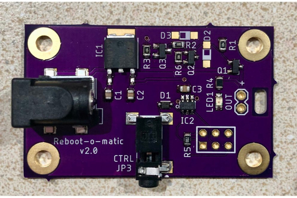
You can get the Reboot-o-matic on Tindie, starting for $15. More information can be found on the project page on Hackaday.

DIY GPS Tracker Features Three Arduino boards

Duane Bester has built a GPS Tracker From Scratch Using 3 Arduino boards to make a GPS tracker and a data logger. A flash of idea came to him, to combine the new Arduino Nano 33 BLE Sense with an SD card and GPS module for a project that records GPS and IMU data. So he opted to buy the Nano 33, the MKR Mem Shield, and the MKR GPS Shield and couple all of them together. He later found out that these boards aren’t footprint-compatible, so He combined them with a breadboard. It took time to get all the plugins installed and everything connected correctly. The biggest challenge he faced was the GPS module, and he says “It really helps to start debugging the GPS’ example code outside; where the satellite signal is available.” After successfully vetting the Prototype code for the arduino, he went ahead to build a custom PCB.

The plain PCB boards

For the PCB design, he used easyeda to build his custom PCB. The first thing he did was obtaining the schematics from the Nano 33, the MKR Mem Shield then the MKR GPS Shield. The schematic was easy to access via Github. Since they are Eagle schematic files, the Eagle trial version was used for an in-depth analysis. After that, he copied the full Nano 33 BLE schematic as it is, as well as matching up the component names and numbers. He then included the GPS module then he had to figure out how to program through J-Link. To ensure it’s optimal, he went on to send off the design to PCBWay to be built and coupled. This was a smooth process, with some questions concerning the part name and orientation. Few weeks later he received the plan PCB boards in the mail, then six weeks later he got the fully assembled PCB boards.


The fully assembled PCB board

When he wanted to flash the Arduino bootloader, he purchased the J-Link EDU Mini cable to be used for programming the custom board and all the J-Link drivers installed. He finally flashed the bootloader through nRF Connect, and it worked. An Arduino Nano would pop up and connect to his MacBook when he plugged in the USB cable. However, during the course of the build, he realized he had made a few mistakes in reverse engineering, the board. The mistakes he made includes:

The Nano 33 schematic has a Do Not Populate (DNP) for a pull-up resistor on the RESET pin. I should have added test points for this resistor as well. I ended up hand-soldering a 4.7K. This stopped my board from auto-resetting every second (could also adjust the UICR to disable the RESET pin).

The schematic shows a 1M Ohm resistor connecting the USB shield to the ground. But the Eagle file shows 330 Ohm , which should be 330 Ohms. (There is tons of debate and trade-offs here)
He messed up wire with the gesture sensor, so the sensor didn’t work. However, it still measured RGB colors.
He was able to fix the issues mentioned above.

To make the device portable, He added a battery connection, LiPo charging, and load sharing. The device was further equipped with a 5V and 3.3V power rail to power external devices. After making more research, He decided to add more decoupling capacitors and various connectors (including GPIO). Finally, he sent the new design with a more compact PCB layout to PCBWay, and he is currently waiting on the boards to get back. For more information about the project, visit the project page here

The Science Journal is graduating from Google! Coming to Arduino this fall

Arduino and Google are excited to announce that the Google Science Journal will be transferring from Google to Arduino this September. Due to Arduino’s existing experience with the Science Journal and a long-standing commitment to open source and hands-on science, Google has agreed to transfer ownership of the open source project over to Arduino.

The Google versions of the app will officially cease support and updates on 11th December 2020, with Arduino continuing all support and app development moving forward.

Arduino Science Journal will include support for the Arduino Nano 33 BLE Sense Board, as well as the MKR WiFi 1010 Board included in the Arduino Science Kit, with students able to document science experiments and record observations using their own mobile device. The Science Journal actively encourages students to learn outside of the classroom, delivering accessible resources to support both teachers and students – a feature with huge importance in the current climate. For developers, the Arduino version will continue to offer abundant codes, APIs and Arduino open source firmware to help them create innovative new projects.

Fabio Violante, Arduino’s CEO, commented:

“Arduino’s heritage in both education and open source makes us the ideal partner to take on and develop the great work started by Google with the Science Journal. The Science Journal’s core principles of enabling children to learn interactively, in a safe and inclusive environment, are totally aligned with Arduino’s philosophy and approach to education. Taking on the next generation of the Science Journal, we can continue providing the essential tools for STEAM classes that develop with students as they progress through school and university, preparing them for a successful future.”

Arduino has been enabling hands-on learning experiences for students and hobbyists since they were founded in 2005, with its products having been compatible with Science Journal since its 2016 launch. In 2019, Arduino released the Arduino Science Kit, an Arduino-based physics lab that’s fully compatible with the Science Journal. Moving forward, all new updates to the app will take place through Arduino’s new version of the Science Journal, available in September. Users will be able to migrate and access their existing experiments from the Google version of the Science Journal to the new Arduino version of the app by manually exporting and importing them.

The new Arduino version of the app will still allow users to measure the world around them using the capabilities built into their phone, tablet, and Chromebook. Furthermore, Arduino will be providing better integration between the Science Journal and existing Arduino products and education programs. The Arduino Science Journal will continue to be free and open source, with updates and new features added over time, making it ever easier for students to conduct and document innovative science experiments.

Arduino’s version of the Science Journal will be available in September 2020 for both iOS and Android.

e-con Systems launches 4K MIPI CSI-2 camera support for Toradex’s i.MX8 system on modules (SoMs)

e-con Systems Inc, a leading embedded vision camera manufacturer is excited to announce their partnership with Toradex, a leading embedded System on Module provider. Further, e-con Systems has launched a bouquet of MIPI CSI-2 camera module support for Toradex’s iMX8 SoM series, Apalis. Among the camera modules would be e-con’s flag ship 4Kcamera module, e-CAM137A_CUMI1335_MOD. By launching variety of camera modules with different image sensors and various features, e-con Systems enables Toradex Apalis i.MX8 customers to address multiple applications.

e-con Systems’ e-CAM137A_CUMI1335_MOD is based on 1/3.2 inch ON Semiconductor’s AR1335 high resolution sensor with a pixel array of 4208H x 3120V. The camera module supports a M12 holder which allows the customer to interchange various lenses.

Other than the 4K camera module, the initial launch includes e-CAM55_CUMI0521_MOD, 5MP MIPI CSI-2 camera module based on 1/2.5 inch ON Semiconductor’s AR0521 sensor with active pixel array 2592 (H) x 1944 (V). The larger pixel size of AR0521 provides superior low light performance enabling quality imaging systems in varied lighting environments.

Video

In addition, e-con Systems would be soon launching e-CAM130_MI1335_MOD, 4K Autofocus camera module and e-CAM56_CUMI0521_MOD, 5MP MIPI CSI-2 Monochrome module for Toradex’s iMX8 SoMs. Also more cameras would be launched soon for Verdin family of SoMs

“e-con Systems, a pioneer in embedded vision is excited to partner with Toradex, a leading computing solutions provider for embedded industry to launch our bouquet of MIPI CSI-2 camera modules for Toradex computing platforms. Our customers can choose any camera from this bouquet to build and deploy their embedded vision products in no time” said Ashok Babu, President of e-con Systems Inc. “Customers can bring down the time-to-market for their embedded vision products drastically as these cameras are already tuned for image quality and ready for deployment in the field without worrying about camera integration issues for long term supply of cameras”, he added.

“Toradex’s focus is to make embedded computing easy. We know that good camera support is important for many of our customers. We are pleased to welcome e-con Systems to our proven Partner Network. We worked hand-in-hand to integrate their camera in our Yocto Project-based BSP and Torizon, the easy-to-use industrial Linux platform. For customers, this means these cameras just work and you can focus on your application. e-con provides a wide range of camera modules supporting Image Signal Processing (ISP), this provides much better performance on applications processors without dedicated ISP such as the i.MX 8 and i.MX 8X”, said Daniel Lang, CMO, Toradex.

e-con Systems has integrated the camera drivers with Toradex’s Torizon, an open-source software platform with Linux OS. This would provide a smooth out of the box experience for Toradex’s existing customers who have bought iMX8 Apalis SoMs.

Availability 

Customers can order the following evaluation kits for testing the various camera modules with the Toradex’s Apalisi.MX8 SoMs from e-con’s Online store.

Renesas Introduces Bluetooth Low Energy Module for Ultra-Low Power IoT Applications

New RYZ012 Module Provides Multi-Standard Wireless Communication Supporting Bluetooth Low Energy 5 and IEEE802.15.4 Based Standards

Renesas Electronics Corporation, a premier supplier of advanced semiconductor solutions, today announced sample shipment availability of the new RYZ012 Bluetooth® module targeting ultra-low power IoT applications. The RYZ012 is Renesas’ first Bluetooth Low Energy 5 module. It integrates a 2.4 GHz RF transceiver supporting the IEEE802.15.4 multi-standard wireless protocol, Bluetooth Low Energy (LE), Bluetooth LE Mesh, and ZigBee. The RYZ012 features a power draw of only 0.4µA during deep sleep (without SRAM retention) allowing customers to extend battery life. The RYZ012 also includes a battery monitor to measure battery capacity and detect low power in battery-operated devices.

“The RYZ012 module complements our IoT connectivity solutions, featuring ultra-low power in a small form factor, designed to target a wide range of IoT, connected home, asset tracking, and cost-sensitive applications,” said Roger Wendelken, Senior Vice President, Head of MCU Business, IoT and Infrastructure Business Unit at Renesas. “The RYZ012 teams with Renesas’ sensor solutions to offer an end-to-end, device-to-cloud ecosystem.”

The RYZ012 module supports the 2.4 GHz IoT standards without the requirement for an external DSP. This reduces the number of external components required and the overall cost in system integration. The RYZ012 module includes a 32-bit microcontroller with an integrated 512kB flash memory and 64kB SRAM for application support. It comes in two versions: with and without an integrated antenna. This allows for implementation flexibility and the option for longer wireless range requirements.

The RYZ012 module will be certified for use in the U.S., Canada, EU, and Japan.

Availability

Samples of the RYZ012 module (both versions) are available now, with full product availability later this year. To order samples, please contact your local salesperson at www.renesas.com/support/contact.html.=

Tiny ObsidianBoa Dev Board Features Espressif Systems’ ESP32-S2 Board

Greg Davill has posted on GitHub an Espressif Systems ESP32 based development board called the ObsidianBoa. Recently Greg Davill had a successful OrangeCrab crowdfunding campaign, he has however directed his attention to the Espressif Systems ESP32. There are a lot of ESP32 development boards today in the market, however, there is only a handful with a tiny form factor, like the TinyPICO which was launched on Crowd Supply last year. ObsidianBoa has a tiny form factor like the TinyPICO, but with some differences. The TinyPICO makes use of the ESP32 Pico D4, while the ObsidianBoa makes use of the ESP32-S2. About the project, he says on Twitter

“It’s my first time designing boards for the ESP32. Turned this around in about a day while I still had the `new project` motivation. So likely a few bugs in there.”

The ObsidianBoa draws inspiration form the 1Bitsy board, and the iCEBreaker Bitsy, they share similar form factor. At the core of the Obsidian Boa is the ESP32-S2, which features native USB support. This enables the Boa to connect directly to the boards USB port, instead of using the conventional USB / Serial converter IC. The ESP32-S2 features a single, 240MHz Xtensa core. This is in contrast to the dual-core design of the previous ESP32 parts. The ESP32-S2 enables a number of design possibilities, but at the expense of some of the features made previously available in the ESP32 Pico D4. The S2 features a USB-C connector but has no Bluetooth connectivity. The ObsidianBoa’s antenna features the Molex 2.4GHz “On Ground” antenna (P/N 479480001). The board is further equipped with R/G/B LEDs, and also a separate RGB combined status LED, which enables you to get better control of the power consumption of the board. The 1mm x 1mm RGB LED Is the right option for the board because it helps the board cut out the latent current consumption of the built-in controller of the LED, and also ensures the operation runs easily i.e you do not have to incorporate a serial object for you to set colors on the diode.

It is quite impressive to see how Davill successfully embedded a whole lot of components into the tiny form factor board. The board looks like a board with a lot of potentials for developers, so hobbyists and professional developers keep your eyes on it. For now, Obsidian Boa is strictly on a DIY basis. The design files are available for free, and you can replicate or fork as you like from the project repo on GitHub. There is no news about the production of the board yet, but hopefully, as soon as Davill completes the work on the board, production will start. You can visit Davill’s twitter page to keep track of the project progression, and to get more info.

Meet the AtmegaZero: An ATmega32U4 with a Raspberry Pi Zero Form Factor

Arduino and others have produced quite a number of Arduino-compatible boards with small form factors, but most of them are not compatible with standard shields and other platform niceties. Instead, they end up being just breakout boards for the microcontroller. On the other hand of small form-factor development boards, is the low-cost Raspberry Pi Zero which has managed to retain compatibility with the shields developed for other raspberry pi models despite its considerably smaller form factor.

To connect these two words together and provide small form factor Arduino boards that are compatible with a good number of shields on the market, hardware hacker Eddie Espinal recently shared his progress on a new board which he calls the ATMegaZero.

Based on the Microchip ATMega32u4 8-bit AVR MCU which is used in the Arduino Leonardo, the ATMegaZero is an Arduino Compatible development board with looks similar to that of the Raspberry Pi Zero.

Similar to the Pi Zero and other modern Pis in many aspects, the ATmegaZero has the same 40-pin header usually found on the Pi Zero, with pinout almost like that of the Pi. Increasing the similarities with the Pi Zero, ATmegaZero also has a microSD card holder located near the lower pins of the large header, and a 32-pin OLED display port that replaces the MIPI CSI camera connector found on the Pi, on the opposite end of the board. There is no HDMI port here in the ATmegaZero, but there is an 8-pin header that can be used to easily install an ESP8266 based ESP-01 module for WiFi connectivity. The schematics analysis suggests that ATmegaZero also includes a 6-pin ISP header and a reset button.

ATMegaZero fitted with ESP-01 module

Key Features and Specifications include:

  • Microchip ATmega32U4 microcontroller running @ 16MHz
  • 2.5KB SRAM, 32KB Flash, and 1KB EEPROM
  • MicroSD card slot for on-board storage
  • A 32-pin OLED display port, compatible with 30-pin SSD1306 and SSD1331 displays
  • 40-pin GPIO header that is Raspberry Pi-inspired.
  • 8-pin header for ESP8266 based ESP-01 WiFi module
  • UART, SPI, I2C
  • 1x micro USB port for debugging
  • 6-pin header for programming
  • 4x LEDS
  • Reset button
  • Operating voltage: 5V via micro USB port
  • Dimensions: 65mm x 30 mm (2.6″ x 1.2″)
  • Weight: 43 grams

The ATmegaZero works well with the Arduino IDE for Windows, Linux, and macOS.

Eddie continues to share somewhat scanty updates on the development of the board via his Instagram page and based on recent updates, the board is currently under pre-production tests but there are plans to make it available to the general public very soon.

GMK NucBox–Most Powerful Palm-Sized 4K Mini PC Coming on Indiegogo Soon

GMK is planning to debut its in-house palm-sized 4K mini PC named GMK NucBox on Indiegogo, and its pre-launch page is ready. You can sign up to enjoy 24% off here: https://www.indiegogo.com/projects/gmk-nucbox-most-powerful-palm-sized-4k-mini-pc/coming_soon/x/24220054

They claim it’s the Most Powerful Palm-Sized 4K Mini PC, world’s smallest that we’ve ever known, as they manage to pack everything into a metal case with dimension of 626242mm. GMK NucBox comes with 8GB of LPDDR4 RAM and 128/256/512GB of SSD options, in addition to that, it supports MicroSD expansion up to 128GB. When signing up, you can purchase the GMK NucBox at as low as $159 for 128GB SSD while the retail price would be $209 when it hits shelves. Let’s view the specs breakdown:

Featured high-performance Intel Celeron J4125 processor which has 4-core 4-thread up to 2.7GHz frequency and the latest Intel UHD Graphics 600, GMK NucBox will definitely bring your computing to the next level.  Its 8GB DDR4 memory offers seamless multitasking between lots of resource hungry software. On top of that, up to 512GB SSD high speed internal storage enables to boot up your computer and launch apps in just a second.

When it comes to connectivity, it furnishes you with all kinds of interfaces for different types of peripherals. And you can connect the mini PC to as many devices as you can own with bluetooth and WiFi connection up to 867Mbps. With 1*HDMI v1.4, it can totally cover all your needs of work and play, including mobile office, business meeting and home entertainment in 4K resolution. The on-the-go productivity and entertainment has never been so easy, until now.

Don’t forget to sign up to enjoy 24% off on the campaign and purchase the perks at the lowest price possible. click here: https://www.indiegogo.com/projects/gmk-nucbox-most-powerful-palm-sized-4k-mini-pc/coming_soon/x/24220054

Getting Started with STM8S using STVD and Cosmic C Compiler

Last time we examined how to program the STM8s microcontroller using the Arduino IDE. This way may work for developers who are familiar with the IDE and want to build quickly, and professional projects, but there are more ways to get the same result. Thus for today’s tutorial, we are going to examine how to use traditional tools like the Cosmic C compiler along with STVD to program the STM8s microcontrollers.

There are several members of the STM8s microcontroller out there but for this tutorial, we will work with the STM8S103F3P6 microcontroller which is one of the cheapest, and most popular member of the family. The popularity of the STM8S103F3P6 makes it a perfect microcontroller for beginners as you can easily find support for it across several forums on the internet.

For easy prototyping, we will use the STM8sBlue development board which is essentially a breakout board for the STM8S103F3P6 MCU with a USB interface, breadboard compatibility, and a few other components to facilitate the development of prototypes for projects based on the MCU.

In addition to the STM8sBlue development board, we will need the ST-LINK programmer, preferably the ST-LINK v2 programmer.  It will be used to upload firmware from the PC to the microcontroller.

Getting Started with STM8S using STVD and Cosmic C Compiler – [Link]

Espressif Teams up with Amazon τo Introduce The ESP32-PICO-V3-ZERO Alexa Connect Kit

Over the past few years, we have seen companies unveil their Alexa Connect Kit (ACK) for smart homes, like the STM32GO71. However, ESpressif has announced its forthcoming Alexa Connect Kit (ACK) module known as ESP32-PICO-V3-ZERO. The ESP32-PICO-V3-ZERO enables an easy way for customers to create Alexa-compatible devices. With Alexa Connect Kit (ACK) you can quickly and easily build products your customers will love, all at a fixed per-device cost. For your customers, products built with ACK include Alexa control through voice and mobile applications, Amazon’s Wi-Fi Simple Setup, and Amazon Dash Replenishment Service (optional). For developers, ACK enables you to connect your devices to Alexa without worrying about managing cloud services, writing an Alexa Skill, or developing complex networking and security firmware.

ESP32-PICO-V3-ZERO has a small form factor, measuring at just 16 x 23 x 2.3 mm, and based on the ESP32-PICO-V3 SiP. The SiP is based on the ESP32-V3 SoC, with a 4 MB SPI flash, a crystal oscillator, filter capacitors, and RF matching links. It offers 2.4 GHz 802.11 b/g/n, Bluetooth and Bluetooth Low Energy connectivity (BLE) to the host MCU. It is also equipped with a PCB antenna, with the host MCU being able to be connected to the ESP32-PICO-V3-ZERO module via a UART interface.

ESP32-PICO-V3-ZERO Back View

For software features, the ESP32-PICO-V3-ZERO features a pre-programmed ACK module firmware. It is also pre-configured to have credentials and connect to an ACK-managed cloud service. The ACK module firmware is managed by Amazon and enables out-of-box features such as Frustration-Free Setup, Alexa connectivity and Amazon Dash Replenishment. Customers can implement interfacing with peripherals on the host MCU when it is connected to the ACK module over a UART interface. This architecture significantly reduces software development and maintenance complexity for customers, while also providing a rich set of product features.

At the heart of the module is Espressif’s ESP32-V3 SoC, which is an XTensa LX7 dual-core 32-bit microcontroller, which is equipped with Wi-Fi and Bluetooth connectivity. This SoC is designed with TSMC’s 40-nm low power technology. The module comes pre-certified for regulatory certifications such as FCC, CE, SRRC, IC and RCM. Espressif has not announced pricing for the module. you can find development resources on Amazon developer website. After registering as a developer you will be allowed to access the firmware, a module utility for firmware updates, generating barcodes, provisioning products, and the ACK Device SDK 3.1 that contains C source code for the host such as Arduino Zero, or STM32 boards. You can also find more information in the published technical details on the official product page.

TOP PCB Companies