NGK develops high heat resistance lithium-ion battery achieving an operating temperature of up to 105°C

The new battery is scheduled for mass production in September 2020, with potential applications primarily in automotive and industrial IoT devices. 

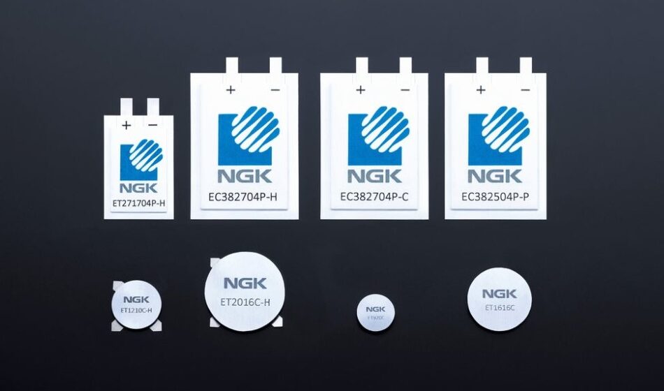
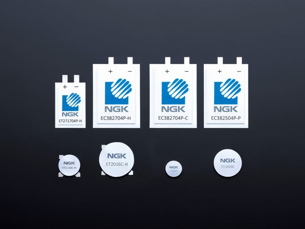
NGK INSULATORS, LTD. (hereinafter “NGK”) has successfully raised the maximum operating temperature of its coin-type “EnerCera Coin” (part of the “EnerCera®” series) battery up to 105 degrees Celsius. Sample shipments are currently underway, with mass production scheduled to begin in September 2020.

In December 2019, NGK developed the world’s first lithium-ion rechargeable battery which has achieved an operating temperature range of -40 to +85 degrees Celsius. As a result of improvements to the product based on customer feedback, NGK recently succeeded in increasing the upper limit of the operating temperature by 20 degrees. The battery is now capable to be used at an operating temperature of up to 105 degrees Celsius, while still maintaining capacity and power. In its fully charged state, when the battery is most prone to deterioration, the capacity decrease is less than 20% even after it is kept at 105 degrees for 1000 hours.

NGK’s EnerCera Coin battery has a unique structure in which a small amount of electrolyte is added to its all-ceramic stacked monolithic body with electrodes and a separator. This provides high thermal stability. The EnerCera battery is categorized as semi-solid-state battery, with performance equivalent to or better than that of a conventional lithium-ion rechargeable battery. The EnerCera battery’s excellent heat resistance characteristics are comparable to those of all-solid-state batteries.

In addition, EnerCera Coin offers flexibility in installation. It can be mounted on a circuit board by reflow soldering, which is a common method for mounting electronic components on board. Furthermore, the battery can also be mounted through injection molding, where molten resin with temperatures of up to 300 degrees is poured into the mold and the battery directly embedded into the resin structure. This allows for the realization of an electronic device with unprecedented design and robustness.

With regard to the latest technological improvements, Iwao Ohwada, Vice President at NGK commented that the:

“development of high heat resistance products was realized through feedback from various partners in the automotive, industrial, logistics and smart card industries. We will continue to work closely with our partners to develop innovative solutions that accelerate the spread of IoT solutions.”

more information: www.ngk-insulators.com

Beelink Gemini M; Ultra-Thin Mini PC Based on Intel GLK-R Processor

Shenzhen based computer hardware manufacturer, Beelink, recently teased the release of a series of new Mini PCs top of which was the Beelink Gemini M, an ultra-thin Mini PC powered by the Intel Celeron J4125 processor running with 8GB of RAM.

Featuring an ultra-thin aluminum enclosure and chassis, designed in a manner that allows for use in a variety of applications, the unique 1.77 cm thinness, 340 grams weight, 11.9cm reduced side size, and Vesa support possessed by the Beelink Gemini M, allows easy integration across different platforms including installations behind a monitor.

Giving users all that they might expect from a full-blown PC, the Beelink Gemini M comes with an assorted number of ports; including 4 USB 3.0 ports, an SDXC card reader, two HDMI 1.4 outputs to drive two displays in parallel in UltraHD, a 3.5 mm audio jack port with combined headphone and microphone, and a Gigabit Ethernet port.

In terms of processing power, the dual-core Intel Celeron J4125 processor being used on the new Mini PC is a member of the recently released Intel Gemini Lake Refresh (GLK-R) family of processors, which are upgraded versions of Intel’s desktop chips, running in a 10 watt PDT (Compared to 6 watts for the Celeron N4100), offering a level of overall performance that positions the Beelink Gemini M in the top category of high performing desktop mini PCs.

The Processor, running at a 2 to 2.7GHz speed, comes with 8GB of RAM, 4MB of cache memory, a 64GB eMMC, and an M.2 SATA 3.0 storage ranging from 128 to 512GB in 2242 format. While the specs so far do not reveal the capacity of the device for a high-quality gaming experience, the device thus comes with an Intel UHD 600 graphics card running at 250 to 700 MHz, capable of decompressing video in UltraHD H.265.

For communications/connectivity, the Beelink Gemini M comes with a Gigabit Ethernet port, a dual-band 802.11b/g/n/ac WiFi 5, and Bluetooth 4.0 all powered by an Intel 3165 wireless card.

Highlight features of the device include:

  • CPU – Intel Celeron J4125, 4 Cores 4 Threads 2.0Ghz, up to 2.7Ghz, Cache 4M
  • GPU – Intel® HD Graphics 600
  • Memory – 8GB RAM LPDDR4
  • Storage – 64GB eMMC or 128GB SSD mSATA + SATA SSD 2242, SD card
  • Video Output – 2x HDMI ports Audio – Via HDMI, 3.5mm audio jack
  • Connectivity – Gigabit Ethernet 1000Mbps, Dual-Band 802.11a/b/g/n/ac WiFi, Bluetooth 4.0
  • USB – 4x USB 3.0 ports
  • Misc – Power button, Fan and heat sink, mounting on the back of the monitor
  • Power Supply – 12V 1.5A
  • Power Consumption – Standby: 0.5W; typical: 12W
  • Dimensions – 11.90 x 11.90 x 1.77 cm
  • Weight – 340 grams

Other PCs being teased include a Beelink GT-R and the GT-R AMD which are both expected to come with WiFi 6 amongst other features.

There is currently no information on the Price and availability of the Mini PC but all indications show that the device could be launched before the end of Q3 2020 with a price range of around $200.

More information on the Mini PC can be found on its Product Page.

[via www.cnx-software.com]

Open Source OAK AI Kit For Spatial AI system

OpenCV has announced their AI Kit called OAK on Kickstarter. It is an MIT-licensed open-source software and Myriad X-based hardware solution for computer vision at any scale. OAK incorporates the OAK API software and two different types of hardware namely OAK-1, a, and OAK-D. The hardware is tiny artificial intelligence (AI) and computer vision (CV) powerhouses, with OAK-D enabling spatial AI leveraging stereo depth in addition to the 4K/30 12MP camera that both models share. With a clock rate of under 30 seconds, the OAK-1 and OAK-D allow anyone to access all the features mentioned above.

If you want to get started in spatial AI, the OAK API is the fastest way, due to the OAK-1  module’s single USB-C connector which provides it with both data and power. The hardware is easy to use, from unboxing the hardware to running an advanced image classifier, it takes less than one minute. OAK ships with neural nets covering which can detect: Faces with mask/no-mask, Age recognition, Emotions recognition, Face detection, Facial Landmark (corners of eyes, mouth, chin, etc.), General object detection (20-class), Pedestrian Detection, and Vehicle detection.

The OAK-1 and OAK-D offer support for Linux, macOS, and Windows hosts. This makes it versatile enough for any prototyping flow no matter the size. You can arrange computer vision + AI workflows with Pipeline Builder, which is a node-based editor that includes previews to ensure that your crops and zooms are passing the right data on to the next step in the process. The hardware offers you feature tracking, hardware-level H.265 support, and 4k output to be used at any time. There are two methods of using the OAK-D to get Spatial AI results, which include Monocular Neural Inference fused with Stereo Depth and Stereo Neural Inference. Both modes have advantages and disadvantages for specific use cases, which will be discussed.

Monocular AI plus Stereo Depth

The Monocular Neural Inference fused with Stereo Depth neural network is run on a single camera and fused with disparity depth results, with the left, right, or RGB camera used to run the neural inference.

In the image above. we see an example of monocular AI fused with Stereo Depth results. Here, the OAK-D is visualizing the object detection results onto the depth data. The bounding box in the middle of the object is where the depth for the object is being pulled (this is configurable in the API).

  Stereo Neural Inference

When using the Stereo Neural Inference the neural network runs in parallel on OAK-D’s left and right cameras to create 3D position data directly with the neural network. Irrespective of the camera being used, standard neural networks can be used. There is no need for the neural networks to be trained with 3D data because the OAK-D automatically provides the 3D results in both cases using standard 2D-trained networks. The image below is an example of this stereo neural inference running on OAK-D.  In this case face detection followed by facial landmark detection running in parallel on both the left and right cameras.

Once you’re done tinkering, OAK’s modular, FCC/CE-approved, open-source hardware ecosystem enables direct integration into your products. Both OAK modules are available in 3 packs and 10 packs. Backers can add additional modules, and other add-ons, to their pledge in the post-campaign backer management system. The major benefit of OAK is that it provides in a single, cohesive solution what would otherwise require cobbling together different hardware and software components.

Shipping, duty, and VAT will be collected separately post-campaign. This does not include a Raspberry Pi. Due to the global pandemic which has affected the prices of goods and services, shipping prices may fluctuate within a few US dollars. There won’t be shipping to any countries restricted by the US Government, with other shipping restrictions apply. All OAK units will be shipped by December 2020, with post-campaign fulfillment being handled by a third-party service, where backers will be able to add multiple OAK devices and add-ons in addition to their pledge. The project will only be funded if it reaches its goal by Thu, August 13 2020 1:01 PM UTC +00:00.

For more information, visit the product announcement page on Kickstarter.

Super Bright Nixie-Like Linear Dot Display

LED Bar graphs are one of the best ways to provide visual feedback to users in projects where using a screen might be an overkill. Especially in projects where you need to indicate level, intensity, and other values that are worth representing on a bar graph. The quality of LED bar graphs has not really improved over time. Users are still subjected to the low resolution due to spaces between the LEDs, the poor brightness, and high power consumption of the LEDs.

There have been several attempts to fix this, with different products on different electronics stores, but one recent LED bar graph which caught our attention with its next-gen feel and brightness is the Nixie-Like Linear Dot LED bar graph recently evaluated in a blog post on Tindie.

A solid attempt in replacing the classic IN-13 linear bar graph Nixie tube whose price has increased incredibly in the past few years, the super bright High-resolution LED paragraph designed by US-based Studio 449 and provides a modern looking high performing LED bar graph without the huge expense and high-power requirements of the old Nixie tubes.

Featuring a linear array of TLC59283 LED drivers with 128 densely-placed orange SMD LEDs placed 1mm apart, the new graph allows you to attain a resolution of up to 128 points/steps, all on a portable 25 x 150 mm board dimensions, which ensures it does not cause a significant change in the form factor of your project.

The bar graph is lined with shift registers which help create a linear indicator that is easy to control from popular microcontrollers. The display communicates with microcontrollers via an SPI-based interface that makes it possible to individually address all the 128 LEDs with just 6 pins, helping designers save on I/O real estate.

Being able to interact with the 128 LEDs individually via the shift registers means users are not limited to lighting the LEDs up in a linear bar graph manner of the display – as users can decide light up arbitrary LEDs to create Arbitary patterns, whatever you require. This takes the use of the bar graph beyond just electronics projects to props for movies and games.

The bar graph has been certified compatible with different microcontrollers and development boards including Arduino boards. A sample sketch showing how to set up communication between an Arduino board and the bar graph is documented on its Hackaday page.

The bar graph is currently available on Tindie for $20 and without shipping charges which vary based on selected countries.

More information can be found on the product’s Tindie page.

Wireless SD Card Reader using ESP8266

One of the good things about being a maker is the power it gives you to create your own stuff. Believing USB devices have not lived up to their designation of truly being universal and working irrespective of the kind of ports they are plugged into, Hackaday user, Neutrino, recently embarked on a mission to develop devices that function irrespective of the kind of USB port they are plugged into, with the first device attempt being a Wireless SD card reader with FTP support.

The wireless SD card reader allows users to bypass the need to plug the SD card into a device before file operations on it can be performed. Once an SD card is inserted into the reader and the reader connected to a USB port (either with data enable or Power only like that of chargers), the wireless SD card comes on and creates an access point which when connected to, allows users to send and receive files from the SD Card, wirelessly, via an FTP Server.

While wireless card readers have been around for a while they are usually, relatively expensive and the option being provided by Neutrino’s build is a considerably cheaper route to making these useful devices.

Some of the major  low-cost components used in Neutrino’s wireless SD card include:

  • Espressif ESP8266 ESP-12E module
  • 1x Micro SD card
  • 1x Micro SD adapter

As with most DIY projects, Neutrino’s project will, however, still require some optimization before it can be said to be commercially viable. For instance, while it looks really usable and handy, the data transfer rate is still very low as it, for instance, takes the card reader about 30 secs to copy 4 files each of about 100 Kb and around 3 to 4 minutes for a larger file like 10MB. This can be associated with the SPI interface used by the project which is easier to implement but slow in comparison to the SDIO interface typically used in other devices.

The Wireless SD Card reader was designed to be compatible with a wide list of FTP client applications, across different platforms, with Neutrino recommending AndFTP for Android users and  WinSCP or Filzella for PC users.

The project is completely open-source all the files including the schematics, source code, and step by step build procedure are available can be found on the project’s hackster page.

microUPDI – Pro-Micro Based UPDI Programmer

Thanks to the increased popularity of the recent ATtiny series of microcontrollers, there has been an increase in the number of open-source UPDI programmers out there. We have covered quite a number of them including the brilliant UPDI programmer compatible with Arduino IDE but we certainly have not seen the end of new designs. One of the latest interesting UPDI programmers we’ve seen is the project by Electronics Designer; Hans, which leveraged the capabilities of the Arduino Pro Micro 5v/16MHz, to create the simple, cheap, and easy-to-use programmer.

Some highlight features of the programmer as outlined by Hans include:

  • A 6-pin UPDI programming connector
    • UPDI interface for programming and debugging
    • Serial interface for communicating with the target over UART
  • Voltage selection jumper where you can choose between 5V, 3.3V or no target power
  • RXD and TXD LEDs for visual feedback
  • Buffered RXD and TXD lines for high impedance inputs and low impedance outputs
  • Status LED
    • Power up -> LED is briefly lid
    • Normal operation -> LED is not lid
    • Programming -> Activity indicator
  • Small in size (18.3mm x 49.6mm)

Using the Arduino Pro Micro for the project comes with a cost as users may have to make a permanent modification to the board. In order to get the mEDBG firmware for the programmer to run properly, the AREF pin on the Arduino Pro Micro has to be connected to 5V. Sadly, this pin is not available as a physical pin, so users will have to locate it on the board and solder a tiny wire from the capacitor to pin 1 on the voltage regulator as shown in the image below.

The consequence of this modification is that users will henceforth not be able to apply voltages higher than 5V to the Raw pin of the Arduino Pro Micro.

The device usage is quite straightforward. After flashing the Pro Micro with the mEDBG firmware, the device will henceforth present itself to the computer as an mEDBG CMSIS-DAP device. This will show up In Atmel Studio as a generic mEDBG device, and as the Arduino UNO WiFi Rev2 board on the Arduino IDE.  To program the board with the megaTinyCore installed on the Arduino IDE,  all you need do is to just select the Onboard Atmel mEDBG option in the Programmers menu and upload. However, for those who prefer the MegaCoreX, the programmer should be the Atmel mEDBG (microUPDI).

The project is entirely open source and all the design files including schematics, firmware, and build guides are available on the project’s GitHub repository. However, for users who will prefer to not deal with the hassles of making their own and just buy the board, it is available on Hans’s Tindie store for $13 excluding shipping.

More information on the project can be obtained on it’s Github Repo here

Trenz TE0802: Zynq UltraScale+ MPSoC Development Board

Designed and manufactured by our partner, Trenz Electronic, the TE0802 is a development board integrating a Xilinx Zynq UltraScale+ MPSoC device. The board features multiple connectivity interfaces, including DisplayPort, VGA, USB 3.0, and Gigabit Ethernet RJ45. With a cost-optimized ZU2CG UltraScale+ MPSoC, embedded developers and users familiar with Arm Cortex-R and Arm Cortex-A53 processors can get started in applications such as industrial motor control, sensor fusion, IoT, Real-time I/O, and medical devices. The versatile onboard I/O, including push buttons, slide switches, a seven-segment LED display, and 12-pin Pmod connectors, provide everything you need in one convenient package.

The Trenz TE0802 is an excellent choice for getting started with the Zynq UltraScale+ family. Applications that require higher performance may be better served with a Genesys ZU, which features a ZU3EG UltraScale+ MPSoC with additional capacity and processing power.

Features:

  • MPSoC:  XCZU2CG – Xilinx Zynq UltraScale+ MPSoC
    • Package: 1SBVA484E
    • Temperature Grade: Extended (0 to +100 °C)
  • RAM/Storage:
    • SDRAM: LPDDR4 8Gb 256Mx16x 2
    • SPI Flash 256Mb (32M x 8) 133 MHz
    • EEPROMs 2Kb (256 x 8)
  • Interfaces:
    • Two 12-pin Pmod Connectors
    • USB JTAG/UART microUSB
    • 1GB Ethernet RJ45
    • USB 3.0 Host (Type A Connector)
    • microSD Card
    • M.2 SSD PCIe
    • 3.5 mm Earphone Jack (PWM Output)
    • Display Port
    • VGA
    • 4 Digit 7-Segment LED Display
    • 8 LEDs
    • 5 User Buttons
    • 8 Bit Slide Switches
    • Reset Button
  • Power
    • 5 V +/- 10%
    • ~3.5 W
    • 3A recommended for board startup
    • 2.1mm inner diameter/5.5mm outer diameter barrel jack plug
  • Dimensions: 100mm x 100mm

more information: store.digilentinc.com

8 Channel Inductive Load Driver Arduino Shield

The 8 Channel Driver Arduino UNO Shield is designed to enable users to switch inductive loads for up to 800mA each channel and up to 24V DC with no heat-sink needed. It is ideal for such applications as driving 2x unipolar stepper motors, solenoids, relays, and small DC motors. It uses 2x DRV8803 Chip from Texas instruments which is 4 channel low side driver with over current protection. IC’s Internal shutdown protection function is provided for overcurrent protection, short circuit protection, under-voltage lockout, and over temperature. Faults are indicated by a fault output pin that is normally high and goes low if a fault condition occurs. Reset and enable pins has internal pull-down resistors.

The board can be used to drive mainly inductive loads, since outputs are provided with clamp diode for protection.  This shield can drive 2 unipolar stepper motors up to 750mA each with Arduino code. Shield also provides a TSOP1838 IR sensor and pot. IR receiver can help to turn OFF/ON 8 loads using IrR remote, DC motor/stepper motor speed control is possible with the help of onboard trimmer pot.

Note: I have tested this project up to 24V DC, but IC supports supply up to 60V, in case of high voltage operation it is required to change C1, C2, C3, C4, C5 Capacitor’s voltage to 60V, and LED series resistor to 4K7. Arduino and shield can work with 12V single supply. If the supply of load is more then 12V, it is advisable to power up Arduino from USB and VM load supply separate, remove jumper J1 in this case.

Features

  • Supply 9-24V DC (Supply up to 60V Possible Reade Note) For Load
  • Supply Arduino 5V or USB power
  • If Load is 12V, Close the Jumper J1, Connect the supply to Arduino DC Jack or CN1
  • Load 800mA Each Channel
  • Operation LED’s for 8 outputs
  • Trimmer Pot for speed control applications
  • TSOP1838 IR Receiver for Remote controlled ON/OFF Application
  • PCB dimensions 53.39mm x 51.00mm

Arduino Pins Configuration (Arduino: DRV8803)

U1: D13>>ENB1 (ENABLE-1), D0>>RST1 (RESET-1), D1>>NF1 (FAULT-1), D5>>IN1, D4>>IN2, D3>>IN3, D2>>IN4

U2: D12>>ENB2 (ENABLE-2), D7>>RST2(RESET-2), D8>>FN2 (FAULT-2), D11>>IN5, D10>>IN6, D9>>IN7, D6>>IN8

Schematics


Parts List

Connections


Gerber View

Stepper Motor Example

Timing Requirement


Photos

Video


DRV8803DW Datasheet

Introducing SparkFun Services

Electronics retailer SparkFun Electronics has announced the launch of nine new value-added services covering board development, logistics, and training to all its customers. By Rich Pell @ eenewsembedded.com

Over the last decade, says the company, it has tested and refined ideas for services by partnering with companies such as Digi-Key, RedHat, Sphero and u-blox, resulting in creative and mutually beneficial outcomes spanning consultation, development, manufacturing, and logistics, which has helped form the foundation for the following new services :

  • Development Board Design and Manufacturing
  • Custom Assembly
  • Sales/Demo Kit Development
  • Custom Kit Development
  • Tape and Reel
  • Custom Procurement
  • Strategic Inventory Management
  • Multi-Address Shipping
  • Workshops and Training

“From the start, SparkFun has been dedicated to making electronics more accessible,” says Glenn Samala, SparkFun CEO. “With these service offerings, we are able to leverage our development expertise and logistics capabilities to help our business partners achieve their goals.”

“While most of these services are not new to us and were developed to meet the needs of our partners over the last decade, we are excited to now be able to offer them to a wider audience,” says Samala. “By sharing access to our network, we hope to help streamline our customers’ ability to integrate the tech they have into the product they need.”

The first official service customer for SparkFun is FarmHand Automation, based out of Maine, who has contracted with SparkFun for a Custom Assembly part for their autonomous robots.

more information: SparkFun Electronics

Audio VU/Sound Level Meter with LM339

This is an “Audio VU Meter” or “Sound Level Meter”, it is a general-purpose bar-graph Audio VU meter designed for fun projects. All you need is to hook up one wire to the output of the audio amplifier’s speaker pin along with GND and see the magic. The response of the circuit is very fast and it provides beautiful visual representation from audio input signal.

A simplified schematic is provided to give the general idea of the operation.  The signal is applied to a series of 20 comparators, each of them is biased to a different comparison level by the resistor string. In the circuit diagram, the resistor string is connected to the 100K potentiometer which provides reference voltage 1.9V to 12V.

Audio VU/Sound Level Meter with LM339 – [Link]

TOP PCB Companies