Toradex announces availability of Dahlia Carrier Board for Verdin SoMs

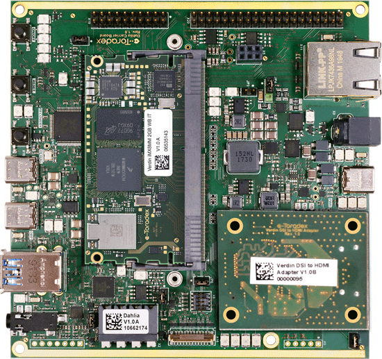
Toradex, a leader in embedded computing, announces the release and availability of Dahlia, the latest addition to its carrier board offerings for the Verdin family of System on Modules (SoMs).

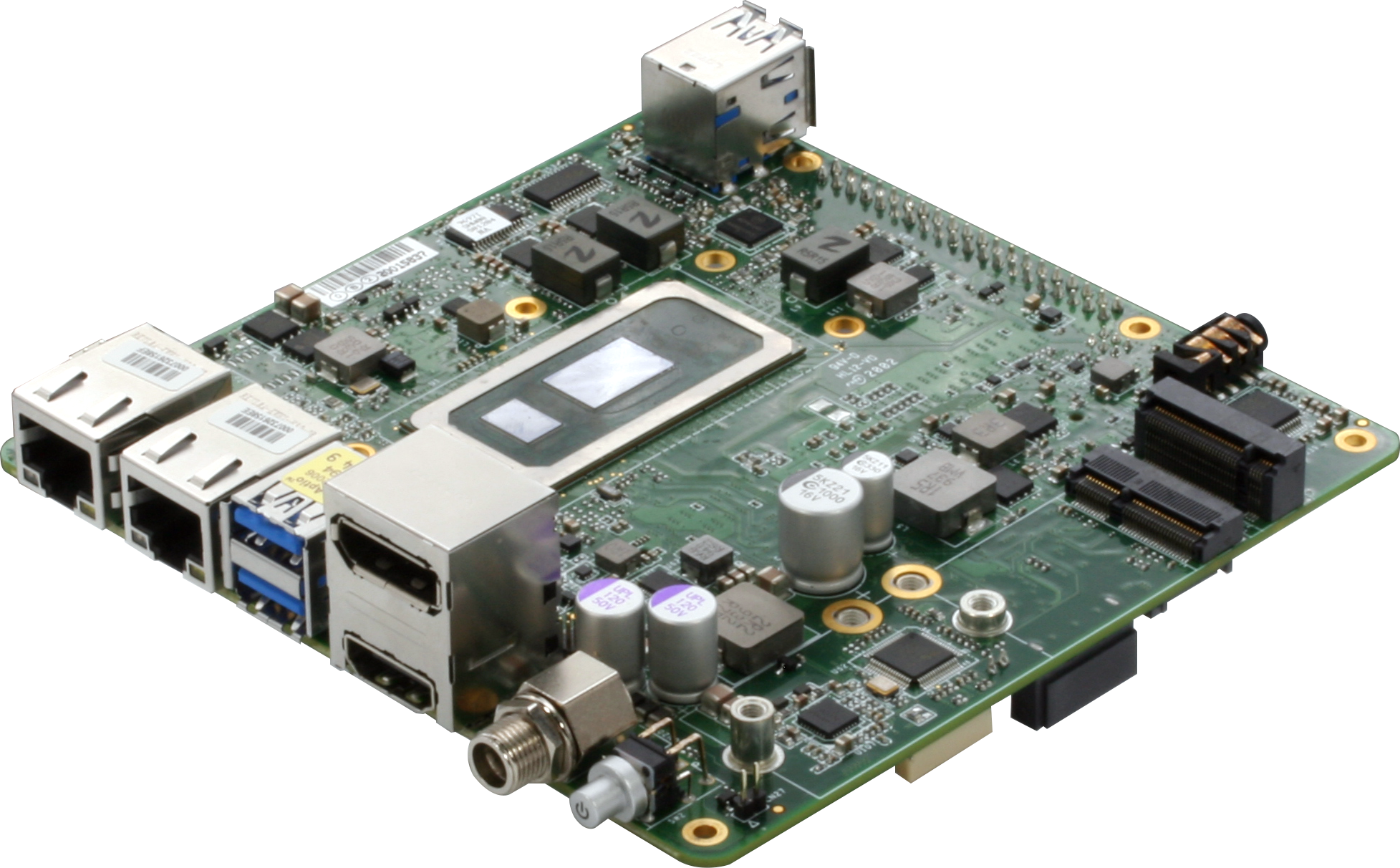
Dahlia provides a simple and convenient development platform for the Verdin SoMs. The board provides easy access to the most common interfaces in a compact 120mm x 120mm form factor. As with all Toradex carrier boards, the design is fully open and is an ideal starting point for your own customized Verdin carrier board.

Highlights:

  • Simple power via USB-C (PD and BC)
  • UART and JTAG interfaces conveniently accessible via a single USB-C connector
  • Gigabit Ethernet, PCI Express, MIPI DSI, MIPI CSI-2, CAN, etc.
  • Free and open design – allowing you to access the complete Altium design and manufacturing data

Verdin modules provide a modern, future-proof set of interfaces focusing on ease-of-use and robustness. The Verdin line expands on the already successful Colibri and Apalis SoM families and comes with the same extensive software, documentation, ecosystem and support. This includes Torizon – the easy-to-use industrial Linux platform – and Toradex BSP Layers and Reference Images for Yocto Project.

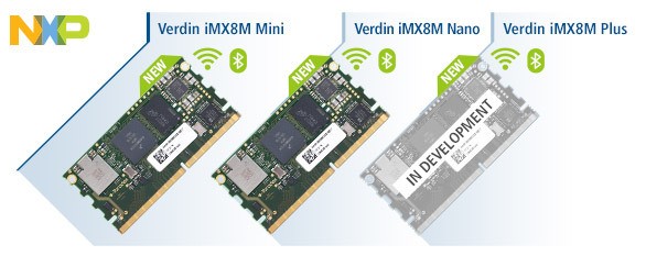
The currently available Verdin SoMs feature the new powerful and efficient NXP® i.MX 8M Mini/Nano applications processors. Currently in development, is a Verdin SoM with NXP i.MX 8M Plus applications processor with Neural Network Accelerator and Image Signal Processing units. Additional Verdin boards are planned. Dahlia works with all current and upcoming Verdin SoMs providing highly scalable and future-proof solutions.

The Dahlia is available on the Toradex webshop, for more information visit Dahlia Carrier Board page.

Push the Edge with UP Xtreme Lite

AAEON, a leading developer of edge computing solutions, introduces the latest from UP Board, the UP Xtreme Lite. UP Xtreme Lite brings the powerful 8th Generation Intel® Core™ processors on a platform that’s even easier for developers on a budget.

The UP Xtreme Lite is designed to provide developers with a platform that’s flexible, powerful, and a great value while not sacrificing performance. Powered by the 8th Generation Intel Core i3/i5/i7 processors (formerly Whiskey Lake), the UP Xtreme Lite provides scalable performance with support for up to 16 GB SO-DIMM memory and SATA III (6.0 Gb/s) available with SATA port and M.2 2280 slot. Expandability for the UP Xtreme Lite includes M.2 2230 E-Key slot, M.2 2280 M/B-Key supporting two PCIe [x1] lanes and M.2 3042/3052 B-Key.

UP Xtreme Lite is designed to be quickly adaptable to any edge computing application. It can easily connect to a range of devices thanks to four USB 3.2 Gen 1 ports, two COM ports, 40-pin HAT header and more on-board connectors. With support for Wi-Fi expansion, SIM card modules and two Gigabit Ethernet ports, the UP Xtreme Lite is a great choice as an IoT or edge network gateway. The UP Xtreme Lite is also the first product in AAEON’s line up to offer support for 5G modules, along with supporting 4G/LTE communication.

Thanks to its expandability and scalable design, the UP Xtreme Lite supports AAEON and UP Board’s AI Core X and AI Core XM modules powered by the Intel® Movidius® Myriad™ X. The UP Xtreme Lite also provides forward looking design, built ready for the next generation of Intel VPUs, the 3rd Generation Movidius VPU (formerly Keem Bay). Developers will be able to unlock AI Edge computing applications thanks to compatibility with Intel® Distribution of OpenVINO™ toolkit as well as popular AI frameworks such as TensorFlow.

“With Intel’s 8th Generation Core processors and scalable design, the UP Xtreme Lite offers great performance and value for developers who require greater performance for their applications,” said Jonah, Product Manager with AAEON’s UP Division. “With great expandability and support for AI applications, UP Xtreme Lite helps to bridge the gap to more powerful solutions for developers on a budget.”

visit www.aaeon.com

LTC7804 40 V 3 MHz Boost Controller with Spectrum Frequency

Analog Devices’ LTC7804 offers low Iq, small solution size, and PassThru™ operation for up to 99.9% efficiency

ADI’s LTC7804 is a low IQ, 3 MHz PassThru operation capable synchronous boost DC/DC switching regulator controller that operates up to a 40 V input voltage. Its low quiescent current extends operating runtime in battery-powered systems. Spread spectrum frequency operation helps reduce radiated and conducted EMI peaks, and up to 3 MHz switching reduces the solution size, ideal for a broad range of applications and markets.

Features:

  • Synchronous operation for reduced power dissipation
  • PassThru operation/100% duty cycle capability for synchronous MOSFET
  • Wide VIN range: 4.5 V to 40 V, operates down to 1 V after start-up
  • Output voltage up to 40 V
  • Low operating IQ: 14 μA
  • Spread spectrum operation
  • Selectable fixed frequency (100 kHz to 3 MHz)
  • AEC-Q100

more information: www.analog.com

Flash an LED from AC-mains power

LED technology is opening the door to a variety of high-power-illumination applications. The circuit in Figure 1 can let you know when ac power is available. To drive a power LED from the ac line requires a converter or a similar arrangement. In this circuit, a passive dropper greatly simplifies the total design. You can also simplify the circuit to run on dc power, which lets you use it from automotive batteries to supply light at night. by TA Babu @ EDN

The design comprises an inrush-limiting resistor, R1; a half-wave rectifier with a filtering capacitor comprising D2, D3, D4, and C2; a relaxation oscillator; and two high-power LEDs. Because the circuit drives the LED with a constant current, you can use any LED color to suit the situation.

The circuit uses a simple DIAC (diode-alternating-current) relaxation oscillator, which activates a constant-current switching circuit comprising IC2 and Q1. The DIAC turns on when capacitor C3 charges through diode D1 and resistor R2 from the mains voltage. After a number of half-cycles of the mains, the voltage on C3 exceeds the break-over voltage of the DIAC, the DIAC conducts, and C3 discharges through R3 and optocoupler IC1. The optocoupler activates the constant-current switching circuit, resulting in a brief, intense flash of light from the LEDs.

High-voltage capacitor C1, part of the passive dropper, limits the current drawn from the power line, as the following equation shows:

A 47 Ω metal-oxide resistor, R1, acts as an inrush-current limiter. Because the LEDs require a lot of energy, it’s not feasible to directly drive them using a small-value capacitive dropper. Instead, this circuit uses a 2200-μF capacitor, C2, to collect and store energy from the power line between flashes. Zener diode D4 limits the capacitor voltage to 12 V.

The easiest constant-current approach is to use an adjustable linear regulator, such as LM317. The regulator maintains a voltage of 1.25 V across series resistor R5. The 1.25 V is the reference voltage of the regulator. Consequently, you can determine the load current with the following equation:

The active current limiting is 320 mA, which is sufficient to produce an intense light flash.

As a note of caution, this circuit has no galvanic isolation from the ac mains. Most nodes are, therefore, at mains potential and hence dangerous. You should not construct this circuit unless you have experience in handling high-voltage circuits.

Larger ComfilePi Industrial Raspberry Pi Controller

Versatile Raspberry Pi-based ComfilePi models 7” CPi-A070WR and 10” CPi-A102WR are joined by a 15” version

Saelig Company, Inc. has introduced the ComfilePi CPi-A150WR  – a Raspberry Pi-based industrial PC with a 15” touch-panel display. Leveraging the compact, ubiquitous Raspberry Pi 3 board, the ComfilePi CPi-A150WR inherits the Raspberry Pi 3’s 1.2GHz 64 bit quad-core ARM Cortex-A53 processor, a Broadcom VideoCore IV GPU, and 1GB of RAM.  The new, larger version has the same capabilities as its predecessors with smaller screen sizes:  the 7” CPi-A070WR and the 10.2” CPi-A102WR.  All models in the series now support AdvancedHMI software, based on the .NET framework, which uses the popular Visual Studio design environment.  AdvancedHMI enables the creation of HMIs that are not possible with other off-the-shelf packages. It creates a true, fast executable for the Linux-based ComfilePi.

The CPi-A150WR’s display is a 24-bit color LCD with a resistive touchscreen, and the controller itself provides 22 x ESD-protected GPIO lines, 3 x USB 2.0 host ports, 1 x RJ-45 Ethernet port, 1 x I2C port, 1 x RS-485 port, a 1 x RS-232C port, and a battery-backed RTC.  It also features stereo audio output as well as a piezo buzzer.  WiFi is also possible using an external USB dongle.  This 15” ComfilePi requires a 12-24VDC 21W power input.

The CPi-A150WR is housed in a flame-retardant ABS enclosure with an IP65 water resistant front panel, and is specified for an operating temperature range of 0degC to 70degC.

The Raspberry Pi is a revolutionary, compact single board computer which typically runs the Linux operating system, but the ComfilePi can be programmed in almost any language, including C, C++, Java, JavaFX, Javascript, python, C#, vb.net, and even emerging languages such as Rust, D, and Nim, as well as .Net Core 2.0 applications. (Android and Windows 10 IoT are not supported.)  Due to the built-in Broadcomm VideoCore IV GPU, the ComfilePi can even render real-time 3D graphics. CODESYS can be used on the ComfilePi by installing one or more of the CODESYS Raspberry Pi Control ModulesCODESYS is a development environment for programming controller applications according to the international industrial standard IEC 61131-3.

Made in South Korea by Comfile Technology, an innovative HMI controller manufacturer, ComfilePi products are available now from Saelig Company, Inc., Comfile’s authorized North American technical distributor.

A Touchscreen Reflow Oven Controller Using an Arduino Pro Mini

We have seen people make many simple reflow ovens, comprising of an old toaster oven, a Solid State Relay (SSR), a thermocouple, and a microcontroller to get it functioning. Hobbyists and makers have been converting old toaster ovens into PCB reflow machines in other to save money, rather than buying expensive ones. This has moved Mangey_Dog to design a reflow oven, that looks more like an over the shelf toaster that you can buy at any electronic store, with all the components integrated inside the main chassis. He bought the toaster for the project from a German eBay store for around £22, and due to his limited budget, and due to the pandemic that delayed the shipping of the part from china he couldn’t buy all new components. He settled for a used German-made 1000-watt Kleiner pizza oven, which wasn’t totally perfect due to its 1000-watt, but met the specifications he needed for this build, and sort for components locally.

After turning on the oven, he found out unfortunately that the oven’s heating elements weren’t what he wanted. They were slow at heating up to temperature, only rising at one degree per second. To increase the heat, he wrapped the heating chamber with ceramic insulation, which was supposed to be installed in the original oven, but likely left off so as to cut costs. He also equipped the oven with a halogen heating element, which he says increased the oven up to 6-degrees per second.

As he progressed with the build, Mangey_Dog integrated an Arduino Pro Mini and touchscreen interface from Nextion displays, although he is not a fan of their product due to the low quality of parts he bought from them over time, however, the display part he got from them for the project offered some nice graphics to control the oven, then a thermocouple to sense the accurate temperature readings, and a dimmer module rated at 4000W to maintain the heating components, instead of a solid-state relay. The Arduino and the dimmer work together to enable efficient circuit control overheating temperatures around the chamber. The Arduino and dimmer control kept the current in the house steady without any bulb flickering when it was turned on to full power.

He programmed the oven, to have two lead functions and three additional profiles that you can tweak to your taste, and save it to be loaded whenever you turn on the oven. He powered the Arduino through an off the shelf adapter. In summary, it was a good build, however, when engaging in such build, all safety has to be observed. Mangey_Dog talks about his experience while building the oven. He says:

“As I mention in my video, I made a little mistake that triggered the RCD for the circuit I was on in the house. It was stupid as I was taking logic level digital knowledge and tried to use that on a mains connected circuit. It was an educated guess, and I was WRONG! I really should have seeked (sic) advice first before trying to filter a live mains connected electronics.”

The only problem he has with the build is the halogen heating element he incorporated, because of it emitting some infrared rays however, he plans to swap it out in the future with some traditional heating system. For more information about the oven build, visit Mangey_Dog’s YouTube channel.

Audio VU/Sound Level Meter with LM339

This is an “Audio VU Meter” or “Sound Level Meter”, it is a general-purpose bar-graph Audio VU meter designed for fun projects. All you need is to hook up one wire to the output of the audio amplifier’s speaker pin along with GND and see the magic. The response of the circuit is very fast and it provides beautiful visual representation from audio input signal.

A simplified schematic is provided to give the general idea of the operation.  The signal is applied to a series of 20 comparators, each of them is biased to a different comparison level by the resistor string. In the circuit diagram, the resistor string is connected to the 100K potentiometer which provides reference voltage 1.9V to 12V.

As the input voltage varies from 0 to 1.9V, the comparator’s outputs are driven low one by one, switching on the LED indicators. This circuit will work with the audio signal level from 1.9V to 12V, it will not work with the audio line signal.  String resistor values calculated to use this project with audio amplifier of 1W to 10W. PR2 provided to adjust the input audio signal level. Testing the board is simple, keep both potentiometer PR1 and PR2 at the center, hook-up 2 wires GND and Input signal to Audio amplifier speaker out, adjust the PR1 so all LEDs are in ON condition at the full audio signal level.

Note: This project can be used in many other applications by altering the string resistors value. Possible applications are bar graph voltmeter, battery level monitor, sensor value monitor.   

Features

  • Supply 9V to 12V DC
  • Load Current 200Ma (When all LED’s are ON)
  • Input Signal Level 1.9V to 12V
  • Can be used with 1W to 10W Audio Amplifier

Schematic

Parts List

Connections

Gerber View

Photos

Video

LM339 Datasheet

ECM3532 AI Sensor Board

Ultra Low Power Sensor Board for Artificial Intelligence at the Edge.

The ECM3532 AI Sensor board is an ultra-low power AI platform with sensors that can run many algorithms: sound classification, keyword spotting, activity classification, context awareness, defect detection and others.

It showcases the capabilities of the ECM3532 Neural Sensor Processor built with Eta Compute’s patented self-timed continuous voltage and frequency scaling technology (CVFS) producing the lowest energy for inference for machine learning algorithms.

Features

  • 1.4 x1.4-inch board with sensors and ECM3532 Neural Sensor Processor
    • 2 x PDM MEMS Microphones: TDK-Invensense ICS-41350
    • 1 x Pressure/Temperature sensor: BOSCH BMP388
    • 1 x 6-axis MEMS Accel/Gyro: TDK-Invensense ICM-20602
  • Battery cradle for CR2032 battery
  • Bluetooth Low Energy on board: BLE v4.2: ABOV A31R118 and antenna
  • Extension for other types of RF through Micro SD card slot
  • 6 pin UART and power port
  • 64Mbit serial Flash for datalogging
  • 5 LEDs and push button

Getting Started

Users can best experience the versatility of the ECM3532 AI Sensor board in minutes by using Edge Impulse’s TinyML development pipeline and the 6 pin UART port.

See here for a tutorial how to use the board with Edge Impulse: https://docs.edgeimpulse.com/docs/eta-compute-ecm3532-ai-sensor

Rohde & Schwarz Releases New Signal Generator

Rohde & Schwarz (R&S) released the SMCV100B, a signal generator that covers 5G NR extended FR1 frequency range up to 7.126 GHz. It leverages the R&S WinIQSIM2 simulation software, which supports common cellular and wireless connectivity standard. This includes standards for IoT and Wi-Fi.

Working within the automotive industry, the R&S SMCV100B is suitable for end-of-line testing of radios and GNSS navigation equipment. Per a company press release, for Go/NoGo tests, the generator can output GPS, GLONASS, Galileo and BeiDou signals of a single navigation satellite. Predefined, time-limited I/Q sequences can be output for functional tests with fixed satellite positions.

The generator also supports analog and digital radio standards in addition to second and third-generation digital terrestrial and satellite-based television standards.

A direct RF concept to generate output signals for frequencies up to 2.5GHz is used to allow I/Q modulation and RF signal generation for performance in the digital domain. This concept supports enhanced SSB phase noise performance.

Per the company, the R&S SMCV100B, a general-purpose instrument, can be deployed in labs at universities and schools in addition to production lines.

For more information, visit rohde-schwarz.com.

Arduino IoT Cloud Remote App: Monitor and Control Your IoT solutions from Anywhere

Further strengthening the Arduino IoT ecosystem, Arduino last week announced the release of the Arduino IoT Cloud Remote app, which was designed to serve as a mobile companion for the Arduino IoT cloud.

The Arduino IoT Cloud created an easy, fast, robust, and secure way for users to develop IoT based solutions, but to get and interact with the data on a smartphone, users usually have to develop their own apps (or use third-party apps) and connect to the cloud service via its API interface, in a manner that is synonymous with other IoT cloud platforms. However, continuing with their tradition of simplifying development processes, the Arduino team decided to develop the Remote App which will allow users to monitor and control their Arduino IoT Cloud dashboards from their mobile phones.

The APP which is only available on iOS for now (Android version is expected to be released in a couple of weeks), was designed to leverage all the interesting features of the Arduino IoT Cloud including the automatic device configuration (including security configurations), automatic main code generation and access to a broad set of widgets that provides you with the versatility your project requires and enables the set up of project dashboards in minutes.

Like with the web/desktop version, dashboards via the app are fully customizable via a drag and drop process that allows users, to group multiple IoT devices and organize them in any sequence or layout on a single dashboard, using multiple data visualization options including graphs to examine data from the devices.

The Arduino IoT Cloud Remote App provides the kind of flexibility that is required for IoT solutions. It gives users the ability to interact with their devices from anywhere, be it the office, home, factory, or farm, from the palm of their hands, via an interface that is optimized for the screen of their smartphones, rather than having to pull out their tabs or PC every time they need to perform some action on the dashboard.

While we await the release of the Android version, the iOS version of the remote app can be downloaded from the Apple store.

More information on the App, it’s features and the roles Arduino hopes it will play within it’s IoT solution ecosystem can be found on the product announcement.

UPDATE 18/8/2020: Both the iOS and Android versions are available and can be downloaded for free from the App Store and Google Play, respectively.

TOP PCB Companies