Rohde & Schwarz Releases New Signal Generator

Rohde & Schwarz (R&S) released the SMCV100B, a signal generator that covers 5G NR extended FR1 frequency range up to 7.126 GHz. It leverages the R&S WinIQSIM2 simulation software, which supports common cellular and wireless connectivity standard. This includes standards for IoT and Wi-Fi.

Working within the automotive industry, the R&S SMCV100B is suitable for end-of-line testing of radios and GNSS navigation equipment. Per a company press release, for Go/NoGo tests, the generator can output GPS, GLONASS, Galileo and BeiDou signals of a single navigation satellite. Predefined, time-limited I/Q sequences can be output for functional tests with fixed satellite positions.

The generator also supports analog and digital radio standards in addition to second and third-generation digital terrestrial and satellite-based television standards.

A direct RF concept to generate output signals for frequencies up to 2.5GHz is used to allow I/Q modulation and RF signal generation for performance in the digital domain. This concept supports enhanced SSB phase noise performance.

Per the company, the R&S SMCV100B, a general-purpose instrument, can be deployed in labs at universities and schools in addition to production lines.

For more information, visit rohde-schwarz.com.

Arduino IoT Cloud Remote App: Monitor and Control Your IoT solutions from Anywhere

Further strengthening the Arduino IoT ecosystem, Arduino last week announced the release of the Arduino IoT Cloud Remote app, which was designed to serve as a mobile companion for the Arduino IoT cloud.

The Arduino IoT Cloud created an easy, fast, robust, and secure way for users to develop IoT based solutions, but to get and interact with the data on a smartphone, users usually have to develop their own apps (or use third-party apps) and connect to the cloud service via its API interface, in a manner that is synonymous with other IoT cloud platforms. However, continuing with their tradition of simplifying development processes, the Arduino team decided to develop the Remote App which will allow users to monitor and control their Arduino IoT Cloud dashboards from their mobile phones.

The APP which is only available on iOS for now (Android version is expected to be released in a couple of weeks), was designed to leverage all the interesting features of the Arduino IoT Cloud including the automatic device configuration (including security configurations), automatic main code generation and access to a broad set of widgets that provides you with the versatility your project requires and enables the set up of project dashboards in minutes.

Like with the web/desktop version, dashboards via the app are fully customizable via a drag and drop process that allows users, to group multiple IoT devices and organize them in any sequence or layout on a single dashboard, using multiple data visualization options including graphs to examine data from the devices.

The Arduino IoT Cloud Remote App provides the kind of flexibility that is required for IoT solutions. It gives users the ability to interact with their devices from anywhere, be it the office, home, factory, or farm, from the palm of their hands, via an interface that is optimized for the screen of their smartphones, rather than having to pull out their tabs or PC every time they need to perform some action on the dashboard.

While we await the release of the Android version, the iOS version of the remote app can be downloaded from the Apple store.

More information on the App, it’s features and the roles Arduino hopes it will play within it’s IoT solution ecosystem can be found on the product announcement.

UPDATE 18/8/2020: Both the iOS and Android versions are available and can be downloaded for free from the App Store and Google Play, respectively.

FLIR ETS320 – Non-Contact Thermal Imaging Camera Solution for Electronic Testing

Whether you are carrying out scientific research or evaluating a product, heat can be an important indicator of how a system is functioning.

FLIR ETS320 is a thermal camera solution designed for instant temperature checks on electronic devices and printed circuit boards. Made specifically for benchtop laboratory testing, the ETS320 comes with a microscope-style stand that is easy to set up and simplified features that allow users to give more attention to their work without having to worry much about camera controls.

The wireless thermal imager is a nearly affordable solution for engineers and laboratory test technicians looking at how to reduce electronic test times and improve product design. The system has the capacity to measure temperatures across over 76,000 points at a time, locating hotspots and potential points of failure within the component. It can also identify areas with faults and thermal gradients since it is highly sensitive to temperature change of 0.06°C and less.

The design of the ETS320 is such that it provides you with immediate feedback on the component you are testing. It shows crisp thermal imagery on a vibrant 3-inch LCD display and an instant guide to the source of PCB failures.

The camera itself is mounted on a silver pole and locked in place with a thumbscrew, but can still be moved up and down with the help of a fine-adjustment knob.

Some highlight features and specification of the device include:

  • Display – Vibrant 3 inch LCD
  • IR resolution – 320 x 240 (76,800 pixels)
  • Viewing angle – 45° x 34°
  • Focused distance – 70mm ± 10mm
  • Measurement accuracy – ±3% or ±3°C
  • Image capture frequency – 9Hz
  • Temperature Range of Object – -20°C to 250°C (-4°F to 482°F)
  • Connectivity – Connect PC to USB for immediate sharing of thermal data
  • Weight – 1.27 pounds
  • Dimensions – 5.9 x 11.8 x 8.7 inches

The FLIR ETS320 comes powered with an internal battery that holds enough charge for several hours of testing, plenty of storage space to save images, and a control panel close to the LCD panel.

The ETS320 works with Windows and Mac operating systems. It comes with FLIR tools and software packages that allow users to generate reports based on the thermal data collected.

More details can be found on the FLIR’s shopping page where the product sells for £2,599.00 excluding VAT.

Soldering RT1 – A Universal Weller RT Soldering Station Offering Tweezers support

Hand soldering is a very important skill to have in every electronics maker’s skill set. Soldering is pretty easy and can be a fun activity. With enough practice, it is an easy skill to pick up. These days, components are becoming smaller and more compact. This could increase the chances of soldering issues occurring. One has to have a soldering station that will handle different tips for different sizes of components. Enters the Soldering RT1 by Riccardo Pittini. Soldering RT1 is a soldering station compatible with Weller RT tips (12V 45W+ and more). It is custom developed, and perfect for SMD work. The Soldering RT1 supports the following tips: RT Micro, Pico, Ultra, and SMD tweezers. The Soldering RT1  is portable, compact, performant, plain and simple.

  Soldering RT1 Board

The Soldering RT1 features two independent channels and 1.8″ TFT full-color LCD. Its hardware MOSFET supports more than 10A continuous current !! (repetitive peaks of more than 50A). The Soldering RT1 is easy to use and portable, it is compatible with Weller RT1. It is open source, and fully Programmable (temperatures 150-450C, preset temperatures, power limitation to use various power supplies), also serial interface and source code are available. The station enables the Under Voltage Lock Out (UVLO) function. It is powered on a standard external 12V power adapter (voltage range 7-24V), with also duty cycle limitation (allows us to use smaller power supplies). It can also run on batteries (7-24V) with Under Voltage Lock Out. The source code is developed based on Arduino, and you can find the full source code and manual in GitLab ( Source code and manual ).


The case can be 3D printed, with two parts in a single print with no support (PLA, PETG, ABS, what you like). “For a fast print it is possible to use a 0.3mm layer height (a complete case print can be done in less than 2h at 60mm/s).” The design is based on three 3d printed parts, two of the parts compose the outer case, while one part allows mounting the receptacle connector and easy soldering of the wires. At the heart of the TFT, there is the microcontroller (AtMega 32U4) and auxiliary electronics. About creating the Soldering RT1, Riccardo Pittini says

“The major challenge in creating the SMD tweezers (really really amazing for SMDs) was to find the mating connector for the original Weller replacement. After finding the correct rare connector, it was rather easy to identify the resistive elements connections and TC connections.”

The simple version of the SMD tweezers utilizes a single channel of the soldering station (by driving the resistive elements in parallel). This will enable a single soldering station to handle a soldering iron and a set of SMD tweezers. And some improvements to the tweezers holder.

Regarding plans for future updates, Riccardo Pittini plans to improve the PID controller response, complete compatibility for soldering tweezers (V1.4), and maybe include compatibility with C245 JBC iron-cartridges. For manual, schematic, and firmware, visit Riccardo Pittini’s project page on Hackaday. You can get the Soldering RT1 on Tindie for $100.

AR18/AR35 Series Single-Turn Absolute Encoders

Broadcom’s AR18 and AR35 series miniature programmable single-turn absolute encoders with resolution ranging from 17-bits to 21-bits

Broadcom’s AR18 and AR35 series are the miniature absolute encoder ASICs designed to cater to the growing demand for space-constrained applications. The AR18 encoder is designed for an overall diameter of 18 mm and offers user-programmable resolution ranging from 17-bit, 19-bit, and 21-bit single-turn absolute output. The AR35 encoder is designed for an overall diameter of 35 mm and offers 17-bit and 21-bit single-turn absolute output. Both the AR18 and AR35 series provide the incremental ABI and UVW in differential mode. Both come with a recommended temperature range of -40°C to +115°C suitable for most industrial applications. Dual-mode operating voltages of 3.3 V and 5 V enable handheld and portable device applications.

Features
  • Miniature absolute encoder ASIC surface mount DFN package: 10.9 mm (L) x 9.1 mm (W) x 1.5 mm (H)
  • User-programmable resolution ranging from:
    • 17-bit, 19-bit, and 21-bit single turn (OD18)
    • 17-bit and 21-bit single turn (OD35)
  • User-programmable incremental output (ABI) resolution ranging from 128 CPR to 8192 CPR
  • Selectable SSI mode communication protocol
  • RoHS-compliant
  • User-programmable commutation signal (UVW) in 2-pole, 3-pole, 4-pole, 5-pole, 12-pole, 30-pole, 32-pole pairs
  • Differential output for ABI and UVW
  • High temperature range of -40°C to +115°C suitable for most of the industrial operation
  • Dual-mode operating voltage of 3.3 V and 5 V, enabling handheld and portable device applications
  • Selectable RS485 mode communication protocol

more information: www.broadcom.com

Compact Low-Power Mini Graphic LCD

DISPLAY VISIONSEA-DOGS102 series graphic LCDs are available in an FSTN positive transflective, STN negative transmissive, and FSTN positive reflective version. These displays have a 2.54 mm pitch and can be soldered directly or plugged into socket strips. Therefore, cumbersome gluing procedures, the need for designing a special mounting device, and error-prone cable connections that may lose contact are no longer a concern.

This LCD family was designed for use in the German industry and will have an availability of 15+ years. The extremely efficient ratio of external dimensions to the active display area helps in designing very compact devices. Furthermore, its low-power use [single supply 2.5 V to 3.3 V (typically 250 µA)] makes it ideal for handheld applications.

The EA 9780-4USB development board and free windows simulator are all users require to evaluate pin connected chip-on-glass LCDs with and without backlight. Simply plug the 2.54 mm connector pins of the display into the socket strips of the development board. Proprietary hardware or software development is not required. Decisions can be made quickly at a minimum expense.

Resources

  • Download the free EA LCD Simulator Software
    • Plug the display into the EA 9780-4USB development board
    • Connect the EA 9780-4USB development board to PC using the USB cable
    • Write text or select graphics, the display will show the content
  • Video: Industrial LCD Display Simulator

Features

  • High-contrast LCD supertwist display (STN and FSTN) with 10 µm dot gap
  • FSTN pos. transflective, STN neg. transmissive, and FSTN pos. reflective version (cannot be backlit)
  • Optional LED backlights in various colors; white, amber, green/red, and customs
  • 102 x 64 pixels (corresponds to 8 x 17 characters or 4 x 12 large characters)
  • UC1701 controller with SPI (4-wire) interface
  • Power supply: single supply 2.5 V to 3.3 V (typ. 250 µA)
  • No additional voltages required
  • Operating temperature range: -20°C to +70°C (storage -30°C to +80°C)
  • No mounting required, simply solder onto PCB

more information: https://www.lcd-module.com/eng/pdf/grafik/dogs102-6e.pdf

Rigol RSA3000N/5000N Real Time Spectrum Analyzers with Vector Network Analysis

Rigol RSA3000N/5000N Real Time Spectrum Analyzers include a built-in tracking generator to offer real-time spectrum analysis and vector network analysis up to 6.5GHz with S11 and S21 reflection and transmission analysis. 

Saelig Company, Inc. has announced that the Rigol RSA3000 and RSA5000 Real Time Spectrum Analyzer series now includes five “N” versions which offer vector network analysis up to 6.5GHz.  Built on Rigol’s Ultra Real platform, these VNAs offer S11 and S21 reflection and transmission analysis.  They feature multi-touch user control via a 10.1” LCD touchscreen. Front panel buttons, keyboard, and mouse input are also available for a straightforward user interface. They run on a Linux operating system to provide a reliable and stable interface, with remote communication access also available.

Customers needing to characterize active or passive components, identify signal path errors, or tune antennas will benefit from this VNA solution, which enables complex measurements including distance to fault and S parameters.  S11, or forward reflection co-efficient, allows engineers to quickly visualize and measure a component’s response on a Smith chart and polar plane while measuring the component’s magnitude and SWR. This is important when characterizing the performance of passive components such as attenuators, splitters, and filters.  S21, or forward transmission coefficient, allows engineers to quickly visualize how amplifiers, filters and cabling components affect impedance or phase as a function of frequency. View phase or group delay as a function of frequency or magnitude to quickly determine and confirm critical specifications. Distance to fault measurements allow engineers to easily debug connectivity issues that cannot be seen from visual inspection. The spectrum analyzer uses signal reflections to calculate the distance to a fault anomaly.  It is useful for debugging communications system and completing cable test as well as for optimizing performance and throughput of a network. The Vector Network Analysis mode complements the other analysis capabilities of Rigol’s Ultra Real spectrum analyzers, including the advanced measurements in Smith mode, real time visualization, EMI pre-compliance analysis, and vector signal analysis tests. An optional Preamp adds 20dB gain to input signals.

The analyzer series measurement possibilities include EMI, RTSA, VSA, and VNA modes in addition to the traditional GPSA mode. Engineers may find it convenient to address multiple RF test challenges with just one instrument, effectively reducing their time and costs and greatly improving their working efficiency.   Advanced Measurement mode provides settings required for transmitter testing such as multichannel power, ACP, and occupied bandwidth.  Quickly recall the limit line compliance with the CISPR standard (e.g. EN55011, EN55012, etc.) to carry out pre-test and monitor the target point with three different detectors.

Made by Rigol Technologies Inc., a leading manufacturer of precision electronic instrumentation for test and measurement, the RSA32000N/5000N series of VNAs are available now from Saelig Company, Inc., their USA technical distributor.

Meet the New Affordable Multi-Color E-Paper Display from Waveshare

E-paper displays need no introductions. They are E-paper displays are fantastic displays, especially for low power applications. However, one shortcoming these displays have is their monochrome black and white nature which literally takes the color out of the things displayed. Some new displays have been able to add one more color but none has been able to give users the kind of color dexterity that is available with other displays like the TFT LCD. All of this is, however,  set to change, as the display manufacturing giant, Waveshare, recently announced the launch of a new 5.65″ 7-color ACeP e-Paper display.

While the display is based on the traditional microcapsule electrophoretic technology used in all e-paper displays, unlike the regular monochrome e-paper displays which represent a pixel data on the display with one bit (0 and 1, black and white), colored e-paper displays represent each pixel with more than one bit, with up to 4bits used in representing every pixel in the ACeP 7-color display, making it easy for developers to represent the colors during firmware development.

Some highlight features of the display include:

  • Advanced Color ePaper (ACeP) technology, supports 7-Color display
  • No backlight and displays last content for a long time even when power is disconnected.
  • Ultra-low power consumption, basically power is only required for refreshing
  • SPI interface, for connecting with controller boards like Raspberry Pi/Jetson Nano/Arduino/STM32, etc.
  • Onboard voltage translator, compatible with 3.3V / 5V MCUs
  • Comes with development resources and manual (examples for Raspberry Pi/Jetson Nano/Arduino/STM32)

The technical specifications of the display are equally impressive with a 120s refresh rate and a wide 170 degrees viewing angle. More technical specifications of the display are provided in the table below:

OPERATING VOLTAGE 3.3V/5V DISPLAY COLOR ACeP 7-Color
INTERFACE 3-wire SPI, 4-wire SPI GREY SCALE 2
OUTLINE DIMENSIONS 138.5 × 100.5mm FULL REFRESH TIME 15s
DISPLAY SIZE 114.9 × 85.8mm REFRESH POWER 50mW (typ.)
DOT PITCH 0.1915 × 0.1915mm STANDBY CURRENT <0.01uA (almost none)
RESOLUTION 600 × 448 pixels VIEWING ANGLE >170°

Waveshare has been one of the frontline developers of e-paper displays and has launched quite a number of innovative displays like the NFC Powered 7.5″ e-Paper among others, but with the 7-Color ACeP Display, they are redefining the e-paper game, inputting an element that will definitely take the bar on the type of things that can be done with e-paper displays a little bit higher.

The 5.65″ ACeP display is currently available for sale on Waveshare’s store for $74.99, which is arguably a fair price for the quality, size, and features embedded in the display.

More information on the display, its features, and applications/use with different development boards can be found on its wiki page on Waveshare’s website.

13 Amazing Gerber Viewer Software for Windows

Gerber Viewer Software for Windows is a software that enables you to open and view Gerber files (GRB files) through the help of their extensive toolset. Some of this software are Gerber editor software also and allows you to view and make changes to Gerber PCB designs. The Gerber file viewer software can export the design in various formats, like SGV, PDF, PNG, PDF, JPEG, etc. You can also take a print out of the design if you want. We have various Geber Viewer software, but I’ll be discussing 12 popular ones.

ViewMate

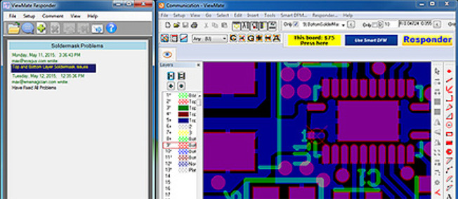
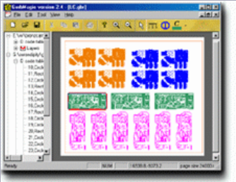
ViewMate from Pentalogix features a broad set of tools available for enhanced viewing functions. Its large array of selection tools enables you to select components, layer options to hide/delete/add layers, visibility toolbar to change layer/component visibility and do much more. It also enables you to select a distance unit from inch, mm, mil, and cm to measure the distance between components. Another function it has is allowing you to add traces/paths to a diagram as orthogonal trace, 90 degrees trace, elbow, circle, add text, etc., but you cannot save the drawing. The drawing with new additions can also be printed. It offers you the ability to experiment with the layers of a Gerber file. You can choose to change the visibility, change the color, and stretch the layers.

GerbMagic

GerbMagic is a free viewer for Gerber RS-274x and Protel ASCII PCB (Protel v2.5 to v2.8 formats). It can also convert Gerber RS-274x and Protel ASCII PCB to PostScript, PDF, TIFF, BMP and RID formats. It is free, simple to use, and feature-rich Gerber Viewer software. It features all the basic tools needed to view Gerber files, such as Layered view, zoom, move, align, and Measure tool as well. You can also save a Gerber file as raster or vector image formats, like: bmp, eps, pdf, tiff, etc.


GerberLogix

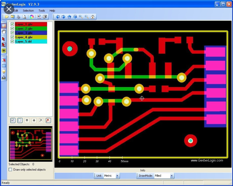
GerberLogix is another simple to use GRB file viewer for Windows. It enables the user to easily manage and view various layers of a Gerber file. You can move the layers up or down manually. It is equipped with all the tools to view all layers, zoom objects, select objects, move objects, etc. Another feature of it is measuring distance between point to point, object to object, and center to center. You can also change the color of layers and objects for enhanced view, and preview a drawing before you print it. Finally you can export Gerber as tiff, jpg, png, and bmp, offering the option of either exporting visible area, or complete area. The Freeware license is only valid for uncommercial usage. A license for commercial usage is available for 109 Euro (plus VAT) per workplace.


GerberGrab

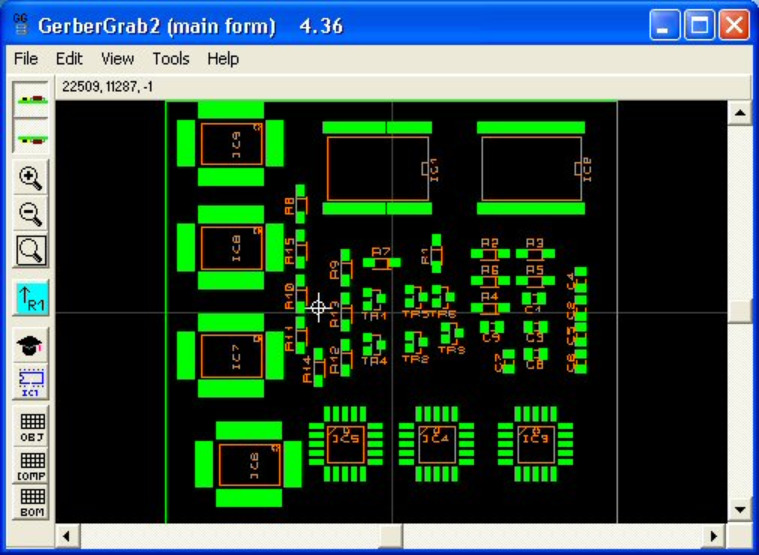
GerberGrab enables basic GRB viewer tools to view Gerber files. You can view the top and bottom sides of PCB layers. Like others, you can view layers separately by selecting or deselecting. You can also search shapes in Gerber files, carry out component scaling and rotation, and generate a component list in CSV. These features are highly valuable for anyone in the PCB manufacturing industry, particularly for contract manufacturers, who may need to check or create bills of material, build documentation, or placement lists, rapidly, off-line and with a high degree of automation.


ZofzPCB

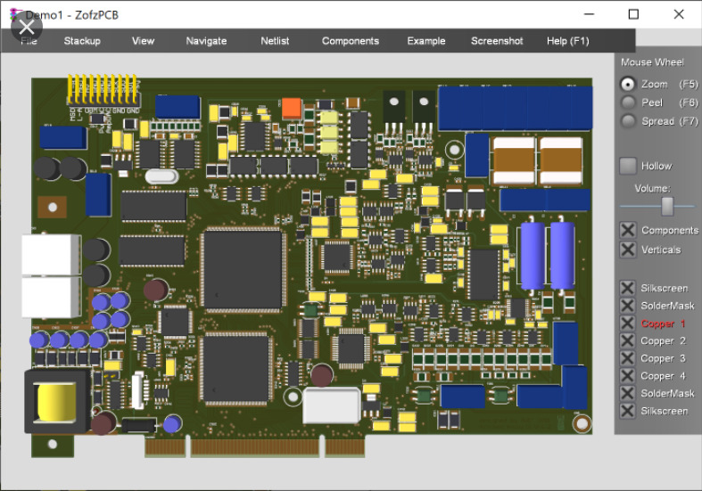
For advanced GRB software, ZofzPCB can do the trick. It is an advanced software to view GRB files. It enables you peel each layer of PCB design separately, allowing you to have a detailed look at the components. This allows you have a separate view of components, silverscreen, solderMask, copper, etc. The software allows you to perform several actions with mouse scroll actions after pressing respective buttons for them, such as: Zoom (F5), Peel (F6), and Spread (F7). ZofzPCB allows you to selectively view/hide components, silkscreen, soldermask, and copper.

Another option lets you view free/blank space on the design board. Another thing you can do with the ZofzPCB is to view the design as wireframe, edit object colors, view as X-ray, or as typical CAD drawing. You can also generate a report with details of components, pins, nets, PCB nodes, IPC nodes, and errors. The ZofzPCB enables you to get realistic 3D rendering from your Gerber files that shows you just how your finished board will look and unveils errors that are difficult to detect in a 2D view. You can also cross-check – synchronized schematic and PCB browsing.


Gerber Viewer

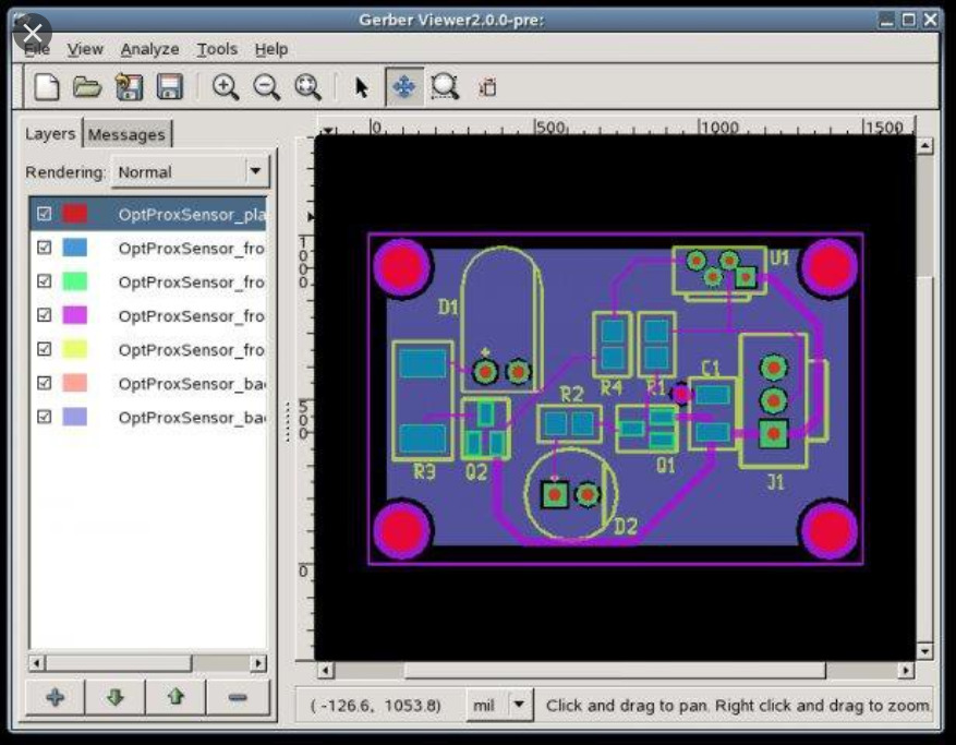
Gerber Viewer features a simple tool with simple viewing options. It enables you to import files to view them, and the tools allows you have a view of the top and bottom view of designs. If you want to view and hide layers, you just have to select and deselect them. You can import Gerber 724-X and IPC2581 files also. The software is an open-source Gerber viewer for Windows.


Viewplot

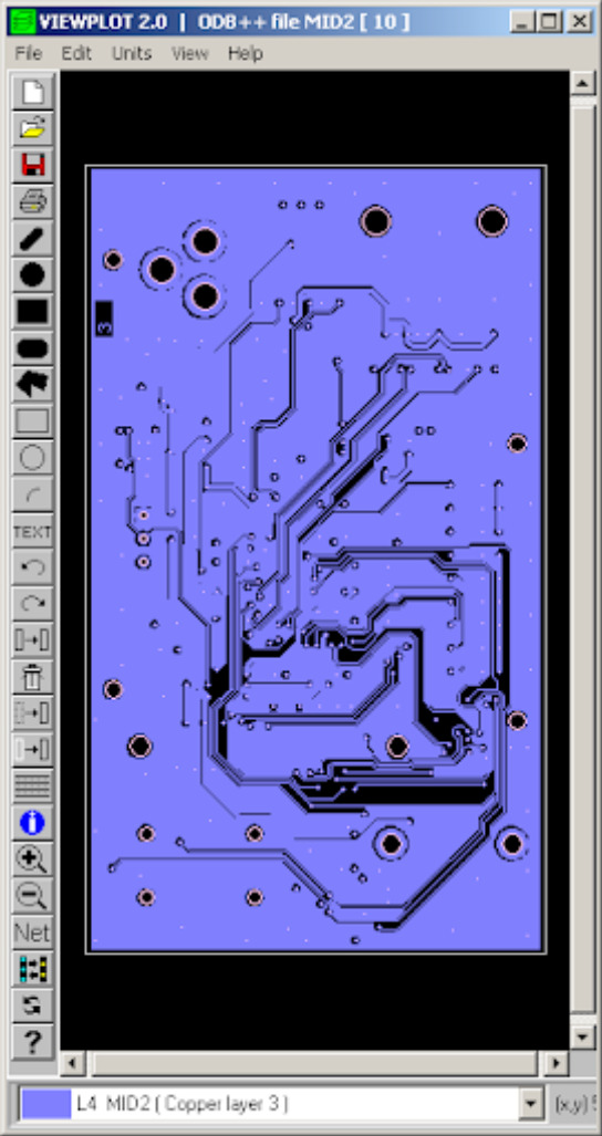
Another GRB editor is Viewplot, which is a paid GRB editor, that allows you view Gerber files for free. It enables you have a good layer-wise view of Gerber files. Every layer has a different color, and by selecting a layer, you can see a highlighted view of it. It enables you to add text, circle, arc, rectangle and other shapes. However, you can not save the file. You have the ability to turn on/off the grid view, and diagram dpi can be changed to 300, 360, 600, 720, 1000, 1200, 1440, 2000, or 2400. You can translate your CAD data in seconds, as a standalone tool or integrated within existing CAD processes. Viewplot also enables you to inspect various CAD formats, take measurements, and manipulate data. You can create high-resolution PDF documentation within the graphical user interface or in batch mode.


GerbEx

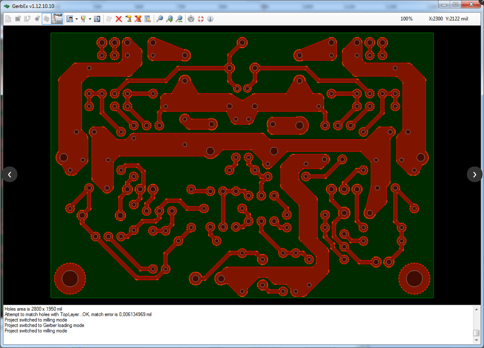
The open-source GerbEx has simple viewing options. The software enables you generate G-code for PCB milling and/or drilling from Gerber and Excellon files. You can zoom and move the drawing around to view GRB files. Also, the software enables you to manipulate layers of the loaded design, with each layer being represented in a different color. Additionally, you can hide or unhide layers and duplicate layers.


FlatCam

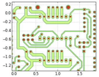
FlatCam Gerber viewer software enables you to edit PCB board or create one. You also have the feature of viewing design layers. Another feature of the software is the option of selecting a component to view its property, and you can also measure distance between two components in mm or inch. You can also isolate routing, board cutout, and non-copper region for a detailed view. You can add shapes like arc, circle, rectangle, etc. You can make double-sided PCBs quickly with a specialized built-in tool that allows you to invert your layers and create alignment guides. One key  feature of the software is the TCL console, which enables the ultimate flexibility for users to automate and implement their own features. Finally, you can view GRB and G-code files, and also export designs as SGV files.

DFM Now

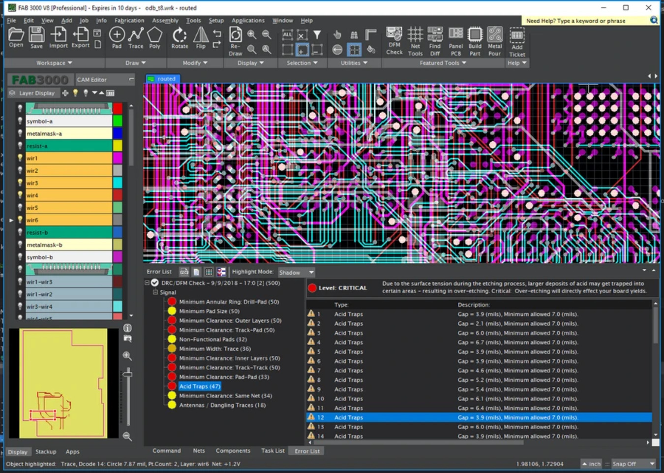
Another GRB editor we will talk about is the DFM Now. The software enables you have a detailed look on Gerber files, like having a top/bottom view of drawings, viewing all layers of files easily, and separately choosing each layer to show/hide. The software also offers a slider zoom, which makes viewing Gerber file very easy. Another feature I like, is the ability to make the board translucent, and view component info when clicked. The software makes it easy to move, delete, rotate, mirror, and flip components. Also, you can add traces, circles, text, etc to the drawing. You cannot save the file, but you can make a printout of the file.


LayoutEditor

LayoutEditor is one of the popular software to edit designs for MEMS and IC fabrication. It is also often be used for Multi-Chip-Modules (MCM), Chip-on-Board (COB), Low temperature co-fired ceramics (LTCC), Monolithic Microwave Integrated Circuits (MMIC), printed circuit boards (PCB), thick film technology, thin-film technology or any other technology using photomasks. It is a free Gerber editor that enables you view and select layers of PCB design, and you can make use of the zoom feature to enhance your view. You can also move and rotate objects, and measure the distance between two objects. You can edit Layers with the software, and add components.


GC-Prevue

With GC-Prevue,  you can view and print Gerber files for 65 USD per year, with support for CAD generated drawings. You can also manipulate layers. The software enables you to set the unit for measuring the distance between parts. You can edit layers by setting layer visibility, deleting layers, and importing layers. You can use the software for verification of design data and quoting.

gerbv

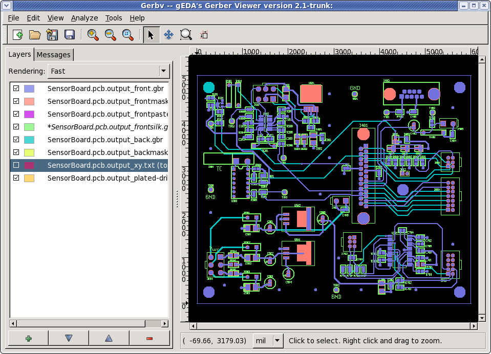
Gerbv is a free viewer for Gerber RS-274X files, Excellon drill files, and CSV pick-and-place files. Gerbv is a native Linux application, and it runs on many common UNIX platforms. A Windows version is also available. If you’re looking for a free tool with which you’ll be able to analyze and validate Gerber (RS-274X) files, try downloading Gerbv. Gerbv is a feature-rich software utility that you can use to view Gerber files, namely those with the RS-274X format. It features several handy tools which should meet the requirements of users’ preferences.

DIY Arduino Nano HV UPDI Programmer

In May, Arduino released a guide on how you can create a UPDI programmer for under $10. Now Dlloydev has posted a guide on Github how to make an Arduino Nano HV UPDI programmer. The Nano HV UPDI programmer will enable you to use the additional configuration settings for the UPDI pin without the fear of getting locked out from the MCU. The Nano HV features 3 programming modes: UPDI, HV or PCHV, with the target voltage at 5V.

To get started, you have to install megaTinyCore, then Install the HV Programmer Firmware. After installation, you click on the green “Clone or download” button, then select “Download ZIP“. When you are through with the download, you unzip the file in a folder on your PC, then load the sketch “jtag2.updi.ino” into the Arduino IDE. Note that you have to uninstall the Write Protect jumper from the programmer for you to carry on with the project, the reason for this is that with a jumper installed, the auto-reset circuit of the programmer is disabled. This protects against accidental overwriting of the firmware and also ensures quick programming sessions by eliminating extra bootloader delays that would be caused by triggering the reset. Moving forward, from the IDE, you select Tools > Board > “Arduino Nano”. Then you select Tools > Port > (serial port used by the Nano). After that, you select Sketch > Upload.

   Schematic

When you are through with the upload, You have to install the Write Protect jumper. Finally, from the IDE, select Tools > Programmer > “jtag2updi (megaTinyCore)”. After going through all these processes, you can now use the Nano HV programmer to “Burn Bootloader” or to “Upload Using Programmer” from the Arduino IDE. However, you have to make sure to choose the appropriate board, chip, and port setting target. Then you can choose Programmer Mode Selection you want. To know if it is programming mode, the red and yellow LEDs will be ON. On startup, the yellow LED will indicate overload status. When the programming mode is set to HV or PCHV, bright blue LED flashes to indicate the HV pulse during programming of the target. On startup, the OVL sense analog input (A6) will be checked. If the voltage on A0-A5 (target power) has dipped below 90% (4.5V), then the yellow LED will indicate overload status by blinking at 4Hz. The user will then need to correct the problem and press reset to clear.

The programmer has three modes you can choose. They include:

  • UPDI Mode: This mode would be used when the UPDI pin is configured as UPDI or for any target device that isn’t HV tolerant.
  • HV Mode: This mode applies the 12V UPDI enable sequence (HV pulse) at the start of the programming sequence. This temporarily reconfigures the UPDI/Reset pin to UPDI mode which will remain in this state until the next POR. This allows programming to occur when the pin is configured as Reset. A power-on reset (POR) needs to occur for any fuse setting changes to take effect.
  • PCHV Mode: Power Cycle High Voltage mode (PCHV) will initiate a power cycle and HV pulse at the start of the programming sequence. At the end of the sequence, a second power cycle will occur which causes any new fuse setting to take effect. The power cycle OFF duration has been set to 10ms. This mode would be used when the UPDI/Reset pin is configured as Reset or as GPIO.

In conclusion, this build enables you to create an Arduino Nano HV UPDI programmer with little resources, rather than having to spend many hundreds of dollars for a commercial one. You can get more information in the guide on Github.

TOP PCB Companies