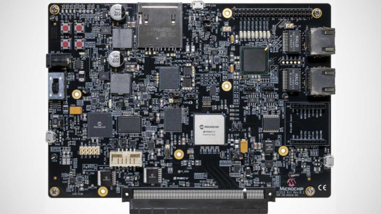
PolarFire SoC Icicle Kit is an affordable development tool for Microchip’s PolarFireSoC, a low-power FPGA fused or integrated with a hardened quad-core 64-bit RISC-V microprocessor subsystem. The Icicle tool is the first development panel for the significant Polarfire SoC, which is the world’s first FPGA and Linux-capable RISC-V system in a single chip. If your purpose is to develop cutting edge apps in integrated artificial intelligence, wired networking, or industrial automation, or just trying to explore RISC-V and FPGAs, this Icicle Kit and its rigorous Mi-V niche of tools are the best way to start.
Features & Specs includes:
PolarFire Soc (MPFS250T-FCVG48EES)
1 x RV64IMAC core
4 x RV64GC core
254K logic elements non-volatile fabric
784 x math block (18 x 18)
4 x 12.7 Gbps SEDES
Secure boot
Memory
2GB LPDDR4 x 32
Storage
1 Gb SPI flash
8 GB Emmc flash or SD card slot (multiple)
Networking
2 x Gigabit Ethernet
Expansion Interfaces
Raspberry Pi-compatible 40-pin header
mikroBUS socket
PCIe gen2
Micro USB 2.0 Hi Speed OTG
4 x UART (via sinle micro USB)
2 x CAN
SPI
I²C
Power
12 VDC / 5 A barrel jack input
On/Off switch
I²C power monitoring measuring four power rails
User Interfaces
4 x User push button
4 x User LED
4 x Power status LED
Programming and Debugging
UART vis micro USB
Onboard JTAG connector or embedded FlashPro6 (multiplexed)
52 x test points
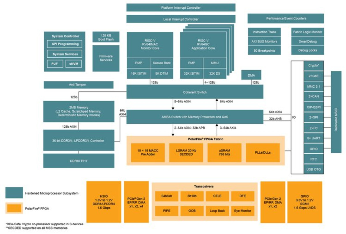
PolarFire SoC Block Diagram
The Icicletool is based on Microchip’s Polar SoC (MPFS250T-FCVG48EES), which is a system-on-chip that uses the effective PolarFire FPGA and a five-core RISC-V microprocessor subsystem together. According to the official PolarFire Soc document, the PolarFire® SoC FPGA family offers an unmatched combo of low power use, heat efficient, and defense-grade security for smart connected systems. This kit is the first system on chip (SoC) field-programmable gate array (FPGA) having an established, well organized RISC-V CPU cluster and a deterministic L2 memory subsystem which is compatible with Linux and real-time apps. PolarFire SoC device offers up to 50% lower energy than alt FPGAs, ranging from 25K to 460K logic elements (LEs) featuring transceivers.
Full production of the board is currently underway and the first units are expected to ship to backers in September 2020. All PolarFire SoC Icicle Kits will be shipped to backers from the Crowd Supply warehouse in the United States. For more information about fulfillment, visit the Crowd Supply Guide page on ordering, paying, and shipping. The retail price (without shipping) of the PolarFire Icicle Kit is $489. The $499 price in this Crowd Supply campaign includes $10 for US domestic shipping. Funding ends on Aug 31, 2020 at 04:59 PM PDT (11:59 PM UTC). more information can be found here.
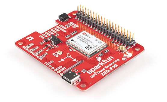
SparkFun has created several Real-Time Kinematics (RTK) as well as dead reckoning boards in the past, but this new ZED-F9RGPS piHAT from the Colorado-based manufacturer is the very first high-precision sensor fusion board to combine both the RTK and dead reckoning features in one professional platform.
The Raspberry Pi add-on board with impressive configuration options takes advantage of u-blox’s automotive dead reckoning technology to provide highly accurate and continuous positioning for automotive and other unmanned vehicle applications including vehicle tracking. The pHAT features u-blox’s 184-channel ZED-F9R GPS receiver module for ADR which supports concurrent reception of four GNSS systems with 20cm accuracy when connected to an RTK base station. The combination of the integrated 3D sensor measurements on the ZED-F9R and the GNSS is responsible for the up to 30Hz real-time positioning rate being delivered.
The ZED-F9R GPS pHAT is touted as an ideal solution for autonomous robotic applications that demand position accuracy under challenging situations. The pHAT can maximize accurate positioning in dense or covered areas as well as provide continuous positioning for areas with poor signal conditions or complete signal loss like short tunnels and parking garages.
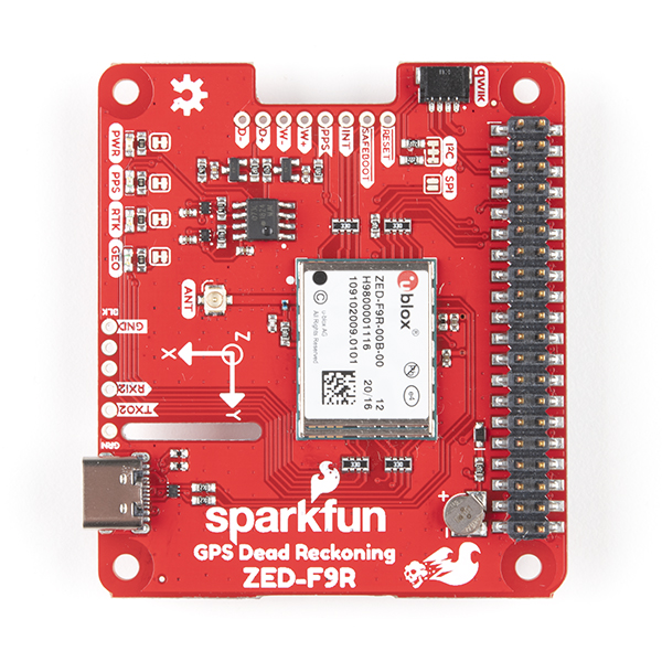
SparkFun’s announcement for this $250 ZED-F9R GPR-RTK dead reckoning pHAT was made alongside a similar $290 open source GPS-RTK dead reckoning breakout model with the same high precision sensor GPS board but without RPi compatibility. “By default, we chose to use the Raspberry Pi’s serial UART to communicate with the module. With pre-soldered headers, no soldering is required to stack the pHAT on a Raspberry Pi, NVIDIA Jetson Nano, Google Coral, or any single-board computer with the 2 x 20 form factor. To give more connection flexibility, the board also breaks out a few 0.1 spaced pins from the u-blox receiver and a Qwiic connector is also added to facilitate connections between the board and Qwiic enabled devices.
For additional interesting features, the ZED-F9R GPS pHAT comes equipped with a micro USB port and an on-board rechargeable battery that provides power to the ZED-F9R module’s RTC in order to reduce the time-to-first fix from a cold start.
The RPi’s GPS-RTK dead reckoning pHAT sells for $249.95 on SparkFun’s product and shopping page, alongside a GPS antenna with a price range of $3.95 to $64.95, depending on the type you want.
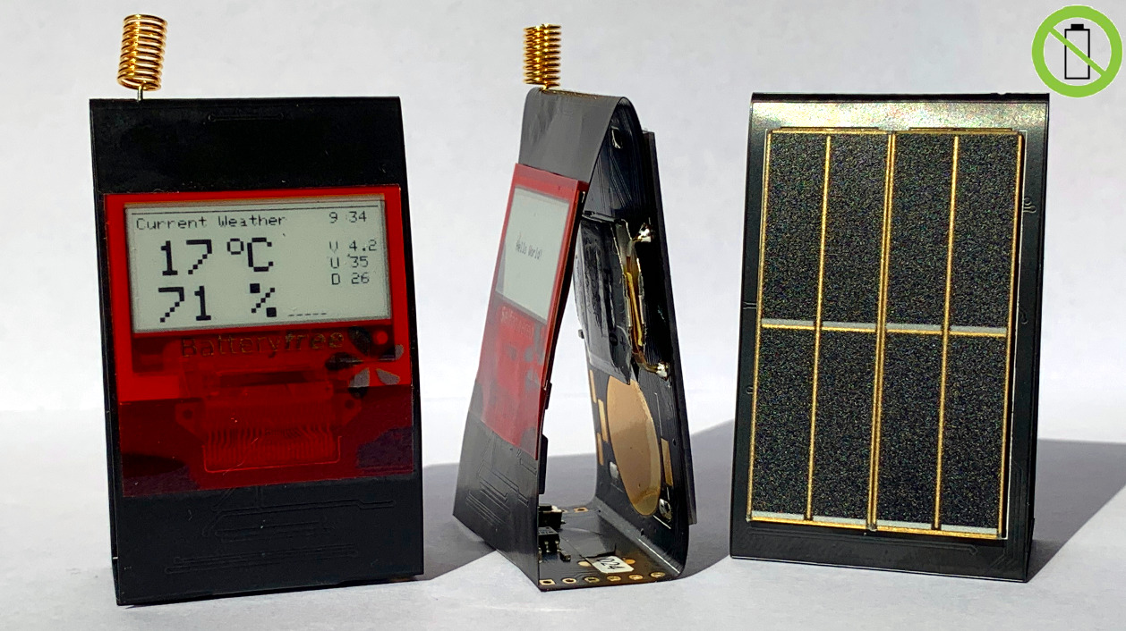
Robert Poser has posted his project on GitHub called PaperiNode, which is a flexible, low power, energy-harvesting, LoRa-enabled, electronic paper display. PaperiNode is ideal for the Paperino (an easy to use micro EPD breakout-board for the Photon or other Arduino-compatible microcontrollers. The eInk-based ePaper display mimics the appearance of natural paper and is capable of holding text and images indefinitely, even without electricity). This makes Paperino perfect for your next battery-driven, a connected project where the display content changes rarely.
Specifications include:
MCU: ATmega328pb (16MHz, 32KB FLASH, 2KB SRAM)
External RTC: MCP7940M
LoRa Chip: RFM95W, Antenna EU_863_870 or u.FL connector for external antenna
EPD: 1.1″ Plastic Logic, 148x70pixel
Flash: Winbond W25X40Cl, 4Mbit
Low power design: Deep Sleep 2.4uA
PV cells: IXYS SLMD121H04L
Energy-harvesting PMIC: E-Peas AEM10941 w/ MPPT
Storage device: EDLC supercap 400mF
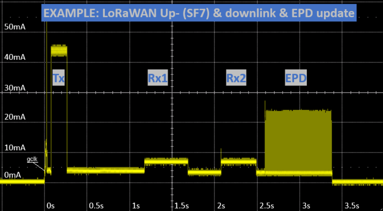
PaperiNode Power Consumption
The PaperiNode has more to offer than just being a flexible EPD breakout board. It is also an Arduino-compatible development board and comes with complete example code and EPD drivers that are capable of running nonstop just from the small amount of power it harnesses from its two IXYS SLMD121H04L solar panels which are mounted on the rear of the device. The process of harnessing the solar energy from the two photovoltaic panels is carried out via a dedicated E-Peas AEM10941 MPPT PMIC, which also acts as a buffer to keep the balance topped up on a large 400mF HA230F EDLC supercapacitor from Cap XX. This supercapacitor device enables the device to store some charge for later use when there are no clear skies for a solar charge, and the solar cells aren’t able to gather the peak Tx current needed by the radio. The supercapacitor also offers enough headroom for some radio capabilities.
The device features the ATmega328PB, which is a very popular MCU in the Arduino family. It features 32KB of flash / 2KB of SRAM, running at 16MHz, and it is housed inside SMD TQFP part instead of the PDIP. The ATmega functions well at low power, and when it’s turned fully off. This is possible via the external RTC IC it features, called the Microchip MCP7940M. The Microchip MCP7940M is capable of sending a configurable interrupt signal via its MFP pin. This enables you to design your applications to utilize only a minute amount of power. One remarkable thing about the EPD module is that it does not need power to hold a static image, couple with the fact that the ATmega remains idle in ” sleep” mode, just waiting for an interrupt from the RTC to turn it on, there is really no power consumption, just about 2.4uA between display updates. One thing that is very important for graphics application is memory space. The ATmega offers 32KB of flash which can be sufficient for application code, but small for image data, font sets. This problem can be solved through the Winbond W25X40Cl 4Mbit FLASH memory found on the schematic.
The device is an open-source device. The device has a second revision which is the successor of the first edition, and contains the following changes:
Reduced deep sleep current
SPI pins exposed on bottom side to connect external sensors etc.
SPI flash added to store measurement data or upto seven pictures
Finally, the device features a DS2401, which is a Silicon Serial Number IC. It is a hard-coded 48-bit serial number, which is unique across all devices. The advantage of this is that it saves you time programming each device with a UUID, and enables a unique identity for each device, making identification of each device very easy. The PaperiNode is now available on Tindie for $59, and you can find support for the project on GitHub.
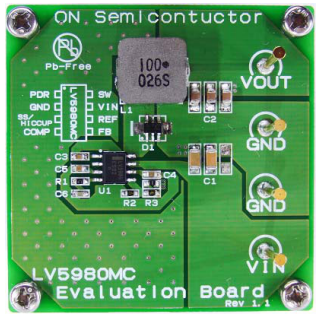
Single chip high efficiency step-down converter, app note from ON Semiconductors.
The LV5980MC is a fixed 370 kHz, high−output−current, Non−synchronous PWM converter that integrates a low−resistance, high−side MOSFET and a Customer Chosen, External Diode for the rectification. The LV5980MC utilizes externally compensated current mode control to provide good transient response, ease of implementation, and excellent loop stability. It regulates input voltages from 4.5 V to 23 V down to an output voltage as low as 1.235 V and is able to supply up to 3.0 A of load current. The LV5980MC includes Power Save Feature to enhance efficiency during Light Load. In low consumption mode, the device show operating current of 63 A from VIN by shutting down unnecessary circuits.
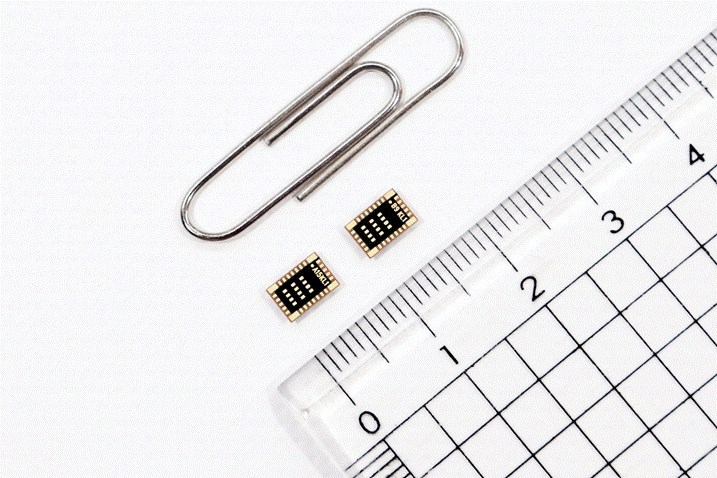
An LG Innotek official is showing a “Bluetooth low energy module for IoT.” Using this module, IoT manufacturers can freely design products in various shapes and size, and its outstanding com-munication performance enables smooth data transmission even with multiple obstacles. (PRNewsfoto/LG Innotek)
LG Innotek announced that it has developed the world’s smallest Bluetooth module. With this development, LG Innotek is gearing up to advance further into the communication module market for Internet of Things (IoT).
LG Innotek’s “Bluetooth low energy (BLE) module for IoT” is a key component that enables data communications for IoT devices such as glucose measuring patches, smart lighting, outlets, switches, wireless earphones, and hearing aids. Thanks to its low power consumption feature, the module is mainly used for IoT devices that require limited power supply, such as small wearable devices.
By linking various IoT devices to the smartphone, users can conveniently track blood glucose levels, remotely control lighting, outlets, switches, and operate wireless earphones or hearing aids at a short distance.
Notably, the IoT products featuring LG Innotek’s BLE module are small and slim but boast of excellent communication performance. With differentiated radio frequency (RF) signal design and antenna technology, and ultra-precision circuit technology, component space is reduced while the data transmission distance is increased.
By applying LG Innotek’s BLE module, IoT device manufacturers can freely design products in various shapes and sizes. This is possible because LG Innotek minimized the module size and mounting space.
LG Innotek’s module is the smallest in the world. This module is 6mm (width) x 4mm (height), which is 75% of the previous model. With ultra-precision, high-density, and ultra-fine processing technologies, more than 20 components including ICs (communications chips), resistors, and inductors, are housed in a single grain-sized product. LG Innotek’s differentiated RF signal design technology minimized component space to eliminate signal interference.
LG Innotek’s BLE module also enables device control and real-time data inquiry even if there is an obstacle between the user’s smartphone and the IoT device. This is because the communication performance of the module is increased by 30% compared to existing products.
In recent tutorials, we have highlighted how useful the ATtiny series of microcontrollers are, thanks to their tiny form factor and a decent amount of processing power, which makes them good choice for projects. where keeping a small device form factor is desired. One other feature that we probably have not highlighted enough, is their low power consumption which combined with their tiny form factor, would make perfect IoT devices. The prospects of their use in low power applications like IoT becomes even more clear when you consider the little amount of power they consume in different low-power modes. The Attiny85, for instance, consumes only 2uA in sleep mode.
Being able to switch between these modes will help you build more robust solutions with longer-lasting batteries using the Attiny series of Microcontrollers. Thus, to ensure you have all you need for this, today’s tutorial will focus on how to wakeup or turnoff the ATtiny85 microcontroller to save power or for any other reason you desire.
Taking the ATtiny85 in and out of sleep modes can be done in several ways including a fully automated software process involving a triggering element like an RTC, or the use of hardware components like a switch. Adopting any of these approaches depends on the requirements for your project but for today’s tutorial we will focus on triggering the sleep mode using a switch.
The tutorial will chronicle the example built by the good folks at bitbanging which implements two kinds of behaviors:
Immediate push on/off: for this, the microcontroller will immediately go into sleep mode when the button is pressed, with all peripherals going off, and it will come back “on” when next the button is pressed
Push and Hold for on/off: This will require the button to be pressed down for a particular timeframe before sleep mode is activated/deactivated.
Ready? let’s go
Required Components
The following components are required to recreate this project;
ATtiny85
SMD to DIP Socket
Pushbutton
LED
220 ohms Resistor
battery/power supply (3.7V – 5V)
Jumper wire
Breadboard
All of these components can be purchased from your favorite online electronics component shops.
Schematics
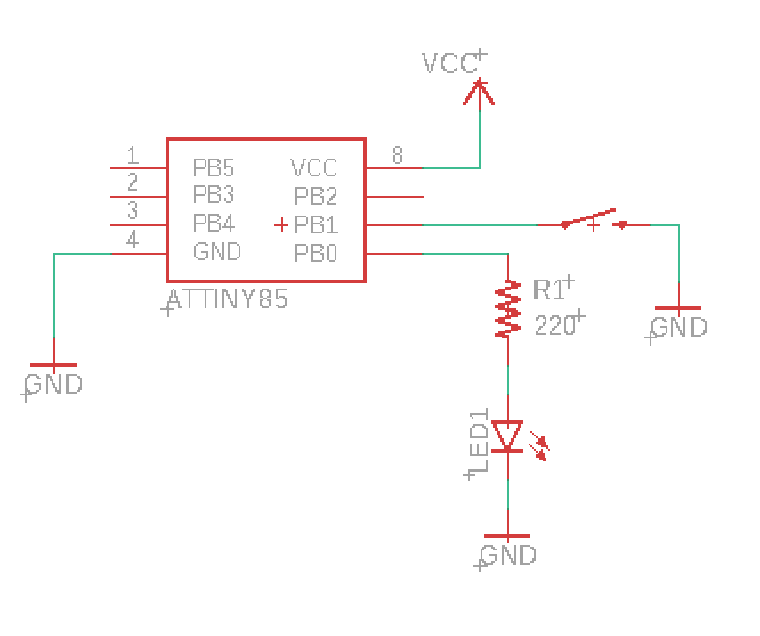
The schematics for the project is quite straight forward. Connect the components as shown in the schematics below;
Schematics Credit: BitBanging.space
The LED, which is being used to indicate the state of the ATtiny (on/off), is connected to pin PB0 of the microcontroller via a resistor (current limiting), while the pushbutton is connected to pin PB1 which is an interrupt enabled pin. You will notice the Pushbutton connection does not have a pull-up (or pull-down) resistor. We will be using the microcontroller’s internal pull-up resistor to prevent the pin from floating.
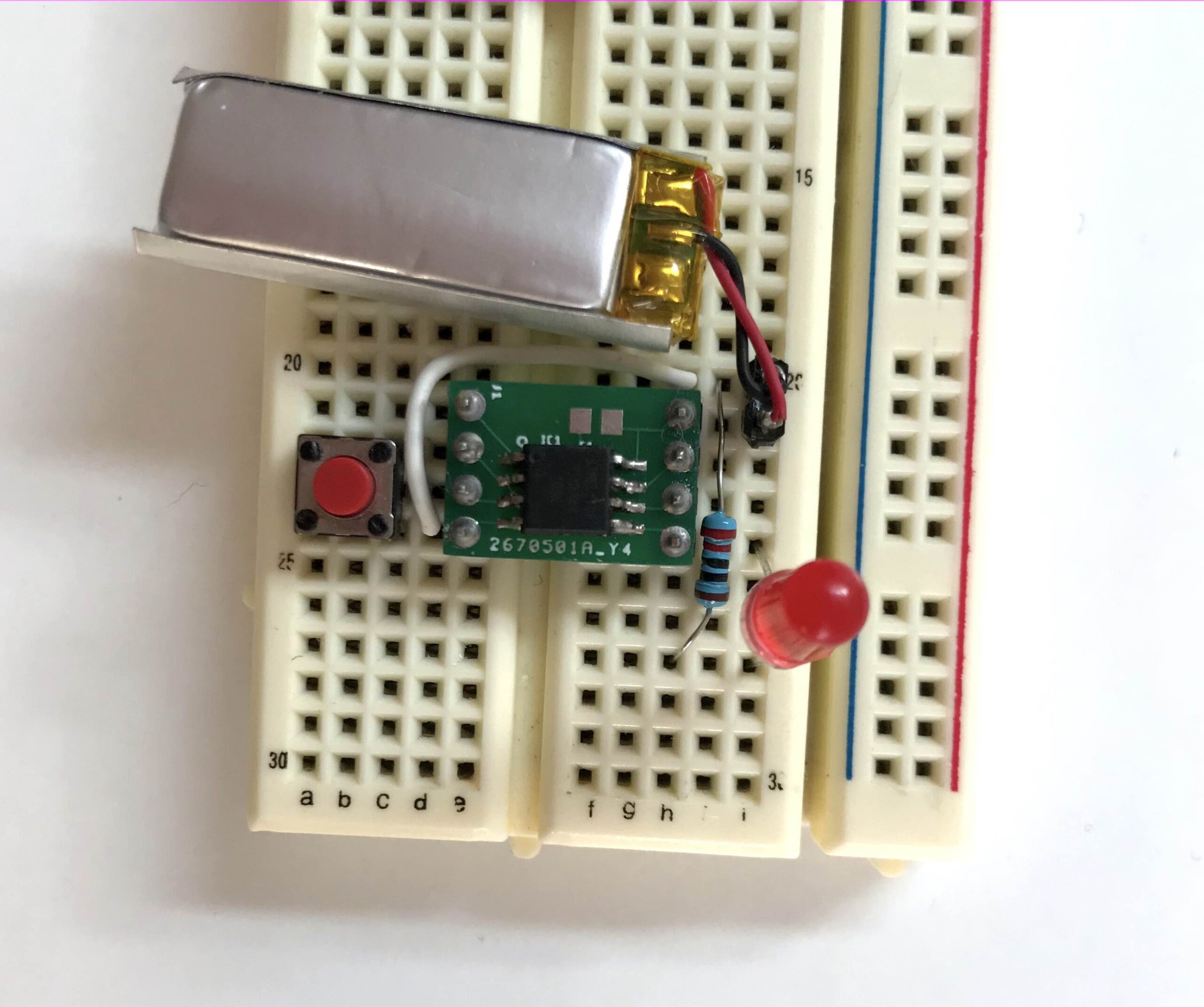
With the connections complete, your setup should look like the image below.
Credit: BitBanging.space
Go over it one more time to ensure there are no errors.
Code
While the schematic for both implementations is the same, and they both leverage interrupts, there are some differences in the code, so we will go over their codes separately. The firmware may be developed using AVR studio but if you are familiar with Arduino C, you can easily port it. We have covered several tutorials on programming ATtiny microcontrollers using the Arduino IDE.
1.Immediate Push ON / OFF
As mentioned earlier, for this implementation, we want the microcontroller to shutdown all peripherals and go to sleep when the button is pressed, and come back up the next time the button is pressed. The logic is simple; the current state of the device either on or off is stored in a variable, such that when a pin change interrupts is triggered by the push button, the device is driven from whatever state it is to the other state. So if the device was on (Running), the triggering of a pin change interrupt will take it to the off (POWER_OFF) state and vice versa.
As usual, I will do a brief run-through and explain some parts of it which I feel may be hard to follow.
We start, as usual, by including all the libraries that are required. I believe their names should easily give them away.
Next, we write the void power_off() function which dictates what happens when the microcontroller is to be switched off. The function includes commands to disable watchdog timer (WDT) and the Brown-out detector while putting the microcontroller in the PWR_DOWN sleep mode.
void power_off()
{
cli(); // Disable Interrupts before next commands
wdt_disable(); // Disable watch dog timer to save power
set_sleep_mode(SLEEP_MODE_PWR_DOWN); // Set sleep mode power down
sleep_enable();
sleep_bod_disable(); // Disable Brown out detector
sei(); // Enable interrupts
sleep_cpu();
sleep_disable();
}
Next, is the main function. The function starts with the interrupt setup, enabling the pull-up resistor on the pin and setting it as an interrupt pin. The default status of the device when powered is also set to running so that the first time the pin is pressed, it switches to the power-off mode.
int main()
{
PORTB |= (1 << BTN); // Enable PULL_UP resistor
GIMSK |= (1 << PCIE); // Enable Pin Change Interrupts
PCMSK |= (1 << BTN); // Use PCINTn as interrupt pin
sei(); // Enable interrupts
status = RUNNING; // Start ON/OFF when power is connected
DDRB |= (1 << DDB0); //Set pin 0 to output for the LE
Next, the main function listens for the interrupt trigger. If it is triggered and the state is set to running, the LED pin is turned “ON” and if it is triggered and status is set to power_off, the LED is turned off.
for (;;)
{
if (status == RUNNING)
{
/* main code here */
PORTB |= (1 << PB0); // LED Pin 0 ON
/* -------------- */
}
else
{
PORTB &= ~(1 << PB0); // LED Pin 0 OFF
power_off();
}
}
}
The last part of the code is the interrupt handling routine. The routine checks if the button has been pressed and changes the status based on the previous status.
ISR(PCINT0_vect)
{
if (BTN_STATUS) //If button is down change status
{
if (status == RUNNING)
status = POWER_OFF;
else
{
status = RUNNING;
/* initialize the device here (timers etc..)*/
}
}
}
The complete code for this implementation is provided below:
#include <avr/io.h>
#include <util/delay.h>
#include <avr/interrupt.h>
#include <avr/sleep.h>
#include <avr/wdt.h>
#define BTN 1
#define BTN_STATUS !((PINB >> BTN) & 0x01)

enum Status
{
    RUNNING,
    POWER_OFF,
};
void power_off()
{
    cli();                               // Disable Interrupts before next commands
    wdt_disable();                       // Disable watch dog timer to save power
    set_sleep_mode(SLEEP_MODE_PWR_DOWN); // Set sleep mode power down
    sleep_enable();
    sleep_bod_disable(); // Disable Brown out detector
    sei();               // Enable interrupts
    sleep_cpu();
    sleep_disable();
}
Status status; // Device status
int main()
{
    PORTB |= (1 << BTN);  // Enable PULL_UP resistor
    GIMSK |= (1 << PCIE); // Enable Pin Change Interrupts
    PCMSK |= (1 << BTN);  // Use PCINTn as interrupt pin
    sei();                // Enable interrupts

    status = RUNNING; // Start ON/OFF when power is connected

DDRB |= (1 << DDB0); //Set pin 0 to output for the LED
    for (;;)
    {
        if (status == RUNNING)
        {
            /* main code here */

            PORTB |= (1 << PB0); // LED Pin 0 ON

            /* -------------- */
        }
        else
        {
            PORTB &= ~(1 << PB0); // LED Pin 0 OFF

            power_off();
        }
    }
}
ISR(PCINT0_vect)
{
    if (BTN_STATUS) //If button is down change status
    {
        if (status == RUNNING)
            status = POWER_OFF;
        else
        {
            status = RUNNING;
            /* initialize the device here (timers etc..)*/
        }
    }
}
2. Push and Hold for on/off
The major difference between this and the first implementation is the desire to introduce a delay. The user has to hold the pushbutton down for a particular period of time before we register it as ON, and the same thing needs to happen to switch the device OFF.
To record how long the button has been pressed, we will be using a timer which will generate an interrupt approximately every millisecond and the interrupt service routine will increment a timer variable until the set time is reached.
Like the first implementation, I will do a brief run through and explain parts of the code which I feel may be hard to follow.
As usual, we start the code by including the libraries to be used.
Next, we define the pin to which the button is connected, initialize the time and set the period of time for which the button must be pressed for it to register to 1000ms.
#define BTN 3
#define timer_init() (TIMSK |= (1 << OCIE0A))
#define BTN_HOLD_MS 1000 // Press button for 1 second
Next, we declare the integral constants for the “Status” variable and also create variables to hold the status of the button (Notice this was not done in the previous implementation?).
Next, we write the setup() function. Here we simply did things that are similar to what you would have done in the setup function of an Arduino sketch. We enabled pull-up resistors, and interrupts on pins etc. each line is commented so it should be easy to follow.
void setup()
{
sei(); // Enable interrupts
PORTB |= (1 << BTN); // Enable PULL_UP resistor
GIMSK |= (1 << PCIE); // Enable Pin Change Interrupts
PCMSK |= (1 << BTN); // Use PCINTn as interrupt pin (Button I/O pin)
TCCR0A |= (1 << WGM01); // Set CTC mode on Timer 1
TIMSK |= (1 << OCIE0A); // Enable the Timer/Counter0 Compare Match A interrupt
TCCR0B |= (1 << CS01); // Set prescaler to 8
OCR0A = 125; // Set the output compare reg so tops at 1 ms
}
Next, we write the power_off() function. This is similar to the one used for the first implementation.
void power_off()
{
cli(); // Disable interrupts before next commands
wdt_disable(); // Disable watch dog timer to save power
set_sleep_mode(SLEEP_MODE_PWR_DOWN); // Set sleep mode power down
sleep_enable();
sleep_bod_disable(); // Disable brown-out detector
sei(); // Enable interrupts
sleep_cpu();
sleep_disable();
}
Next, we write the main function.
The function starts by calling the setup function to implement everything grouped under it. Next, we initialize the device status to running, pushbutton status to “btn_up” and set the pin to which the LED is connected as an output pin.
int main()
{
setup();
Device_Status status = RUNNING; // Set start ON or OFF when power is connected
btn_status = BTN_UP;
DDRB |= (1 << DDB0); // Set pin 0 as output
Next, we write if…else statements to trigger the LED, based on the Device_Status as determined by the status of the push button.
for (;;)
{
if (btn_status == BTN_DOWN)
{
if (timer > BTN_HOLD_MS) // Check if button has been pressed enough
{
if (status == RUNNING)
status = POWER_OFF;
else
{
status = RUNNING;
// setup of the device here if needed;
}
btn_status = BTN_IGNORE; // If status already changed don't swap it again
}
}
else
{
if (status) // Is status RUNNING?
{
/* main code here */
PORTB |= (1 << PB0); // Pin 0 ON
/* -------------- */
}
else
{
PORTB &= ~(1 << PB0); // Pin 0 OFF
power_off();
}
}
}
}
Next, we write the interrupt service routine that checks if the button has been pressed or not to kickstart timer, and the routine that increments the timer.
ISR(PCINT0_vect)
{
if (!((PINB >> BTN) & 0x01)) // Check if button is down
{
btn_status = BTN_DOWN;
timer_init();
timer = 0;
}
else
btn_status = BTN_UP;
}
ISR(TIM0_COMPA_vect)
{
timer++;
The complete code for this implementation is provided below;
#include <avr/io.h>
#include <util/delay.h>
#include <avr/interrupt.h>
#include <avr/sleep.h>
#include <avr/wdt.h>
#define BTN 3
#define timer_init() (TIMSK |= (1 << OCIE0A))
#define BTN_HOLD_MS 1000    // Press button for 1 second
enum Device_Status
{
    POWER_OFF,
    RUNNING
};
enum Btn_Status
{
    BTN_UP,
    BTN_DOWN,
    BTN_IGNORE
};
void setup()
{
    sei();                  // Enable interrupts
    PORTB |= (1 << BTN);    // Enable PULL_UP resistor
    GIMSK |= (1 << PCIE);   // Enable Pin Change Interrupts
    PCMSK |= (1 << BTN);    // Use PCINTn as interrupt pin (Button I/O pin)
    TCCR0A |= (1 << WGM01); // Set CTC mode on Timer 1
    TIMSK |= (1 << OCIE0A); // Enable the Timer/Counter0 Compare Match A interrupt
    TCCR0B |= (1 << CS01);  // Set prescaler to 8
    OCR0A = 125;            // Set the output compare reg so tops at 1 ms
}
void power_off()
{
    cli();                               // Disable interrupts before next commands
    wdt_disable();                       // Disable watch dog timer to save power
    set_sleep_mode(SLEEP_MODE_PWR_DOWN); // Set sleep mode power down
    sleep_enable();
    sleep_bod_disable(); // Disable brown-out detector
    sei();               // Enable interrupts
    sleep_cpu();
    sleep_disable();
}
volatile unsigned int timer; // milliseconds counter
Btn_Status btn_status; // Status of the button
int main()
{
    setup();
    Device_Status status = RUNNING; // Set start ON or OFF when power is connected
    btn_status = BTN_UP;
    DDRB |= (1 << DDB0); // Set pin 0 as output
  for (;;)
    {

        if (btn_status == BTN_DOWN)
        {
            if (timer > BTN_HOLD_MS) // Check if button has been pressed enough
            {
                if (status == RUNNING)
                    status = POWER_OFF;
                else
                {
                    status = RUNNING;
                    // setup of the device here if needed;
                }
                btn_status = BTN_IGNORE; // If status already changed don't swap it again
            }
        }
        else
        {
            if (status) // Is status RUNNING?
            {
                /* main code here */

                PORTB |= (1 << PB0); // Pin 0 ON

                /* -------------- */
            }
            else
            {
                PORTB &= ~(1 << PB0); // Pin 0 OFF
                power_off();
            }
        }
    }
}
ISR(PCINT0_vect)
{
    if (!((PINB >> BTN) & 0x01)) // Check if button is down
    {
        btn_status = BTN_DOWN;
        timer_init();
        timer = 0;
    }
    else
        btn_status = BTN_UP;
}

ISR(TIM0_COMPA_vect)
{
    timer++;
}
That’s it!
IoT or not, there will always be a need to put any device (the entire device or some part of the device e.g display in mobile phones) running of battery in sleep mode. The approach to this will differ based on the core functions of the device but whichever way it is snippets from the code shared above can be leveraged to achieve this.
TDK announces worldwide availability of the InvenSense SmartBug, a compact, wireless multi-sensor solution designed for a plethora of commercial and consumer IoT applications. The out-of-the-box solution enables quick and easy access to reliable and smart sensor data without the need for programming, soldering, or extra modifications. SmartBug is an all-in-one sensor module that integrates TDK’s 6-axis IMU (gyroscope + accelerometer) with magnetometer, pressure, temperature, humidity and ultrasonic sensors, and high-precision algorithms. These algorithms include sensor fusion, HVAC filter monitoring, asset monitoring, gesture detection, activity classification, air mouse monitoring and smart door open/close detection.
The SmartBug module enables accurate and remote monitoring via both BLE and WiFi, and provides autonomous SD card data logging capability for IoT applications with large data volumes. With its small size, flat base and wireless features, the SmartBug is a perfect one-size-fits-all solution that can be stuck almost anywhere, from a simple door to an industrial robot, providing high-quality remote data collection.
“SmartBug will make the process of gathering intelligent multi-sensor data very simple and effective,” says Sahil Choudhary, Product Manager, Motion and Pressure Sensors – IoT, InvenSense, a TDK Group Company. “This module is designed as the smallest complete IoT solution available to deliver quick and easy ‘smart sensor data,’ and is the perfect enabler for any product developer across consumer and commercial IoT applications.”
InvenSense partnerships with Nordic, AKM, Sensirion, and Espressif Systems provide an ecosystem set of components that enable multiple key features within the SmartBug module:
Nordic Semiconductor: Nordic’s latest low-power MCU with BLE 5.2 acquires multi-sensor data from the SmartBug and runs all supported algorithms. It enables high-quality streaming of smart sensor data via both USB and BLE, and provides unique features such as OTA FW upgrade, and support for add-on cards with SD card logging and ultrasonic sensors.
Espressif Systems: The WiFi chip from Espressif expands the wireless data streaming and logging capabilities of SmartBug to higher throughput (up to 2KHz) and longer ranges.
AKM: AKM’s magnetometer enables multiple features including compass data collection, 9-axis sensor fusion for accurate orientation heading, and magnetic anomaly detection for asset monitoring applications in SmartBug.
Sensirion: SmartBug leverages the Humidity and Temperature sensor from Sensirion for data streaming and logging, and humidity and temperature-based events for asset monitoring applications.
Murata’s MYR series are the PicoBK™ DC/DC converters that integrate a coil and a control IC. The ultra-small form-factor measures 2.5 mm x 2.0 mm x 1.0 mm. The MYR series is significantly smaller than discrete solutions. In most cases, these modules occupy less than half the footprint of the same solution implemented with discrete components.
These DC/DC converters achieve high efficiency, low noise, and high heat dissipation. The devices are designed for a 2.5 V to 5.5 V source such as a Li-ion battery. The input voltage of the MYRGC series is up to 36 VDC and suitable for battery applications to industrial applications. The typical efficiency of the MYRGP is 93% at 5.0 VIN / 3.3 VOUT. The control method can be selected fixed, PWM, or PFM/PWM auto switch.
ROHM recently announced the 1608-size high accuracy blue-green chip LEDs, SMLD12E2N1W and SMLD12E3N1W. These products support the adoption of Color Universal Design (CUD) in a variety of applications, such as fire alarm system indicator lights, industrial equipment warning lamps and public transportation information displays.
Color is considered to be one of the most important means of communication and is used in a variety of ways – daily. However, approximately over 200 million people with P-type and D-type color deficiencies around the world find it difficult to distinguish between red and green, possibly resulting in information being inaccurately conveyed – depending on the combination of colors used. Furthermore, since color vision can vary from person to person, it is difficult to perceive how different people see certain colors, which can be very inconvenient and also problematic as other people may not notice this deficiency.
As a result, there is a growing need in the society to implement Color Universal Design that takes into account the various types of color vision in order to deliver information accurately to as many people as possible. ROHM succeeded in developing blue-green chip LEDs with special wavelengths. These products are ideal for implementing Color Universal Design in a wide range of devices, utilizing a vertically integrated production system from the element fabrication stage and leveraging ROHM’s strength thorough quality control.
The SMLD12E2N1W and SMLD12E3N1W are the first* 1608 size LEDs to be certified by the Japanese NPO (Non-Profit Organization), Color Universal Design Organization (hereafter referred to as CUDO) – making it possible to achieve color schemes and designs that can be easily discernible by everyone, including those who cannot distinguish differences in color.
*Based on ROHM’s investigation as of June, 2020.
In addition, adopting a new resin allows ROHM to significantly extend the LED lifetime while reducing the degradation of light intensity compared to conventional epoxy resins and improving the mold strength compared to the silicone resins while providing superior reliability. ROHM also offers AEC-Q102 qualified products that ensure worry-free use in automotive systems and industrial equipment demanding extreme reliability.
GuRu Wireless, a developer of mmWave wireless power solutions, announced the availability of its new evaluation and development kit. The new kit was developed to facilitate testing, evaluation, and proof-of-concept designs, all of which is based on the company’s proprietary, 24GHz, smart RF lensing technology.
Further, the kit can power devices over-the-air from three feet and further.
“GuRu received incredible feedback on prototypes unveiled earlier this year at the Consumer Electronics Show and is now excited to empower partners and OEMs for innovating products for staying powered and connected in meaningful ways,” said CEO of GuRu Wireless Florian Bohn, in a press release. “Via our latest evaluation kit, partners can assess potential use case scenarios and implement wireless power for desired applications.”
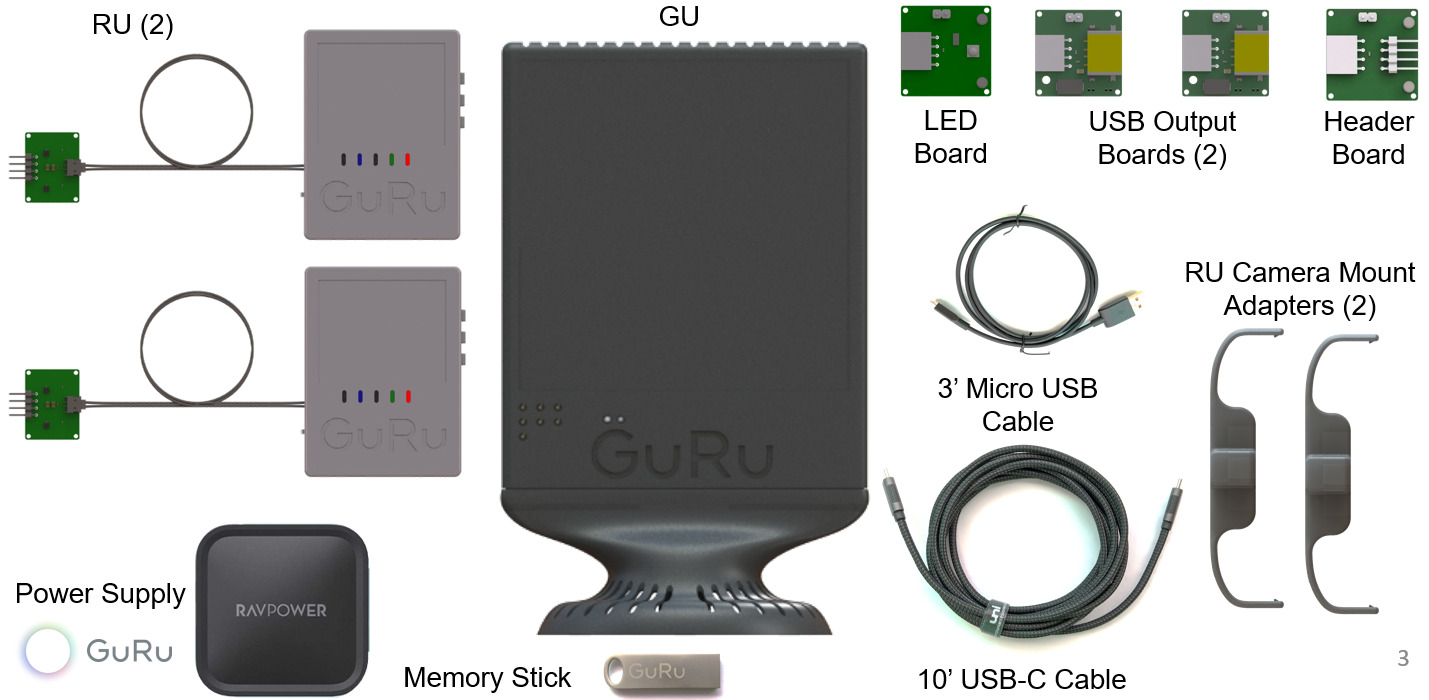
The eval kit for wireless power transmission over-the-air contains the following per the release:
Transmitter: For desktop type environment, in a convenient, small form factor
Power Supply: 15/20 Volt DC for transmitter (industry-standard USB-C connector)
Recovery Unit: 5 Volt DC with a two-pin connector (Extra recovery units available upon request)
Software & Button Interface: For control and monitoring. Updates periodically available
Specialized Software and Hardware: Add-ons and updates available for partners