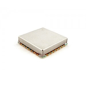
Z-Communications, Inc. announces a new RoHS compliant fixed frequency phase locked loop model SFS9250C-LF operating in the X-band. The SFS9250C-LF is a simple to use plug and play PLO allowing for quick integration. It is designed to produce a fixed signal at 9250 MHz while locked to an external 10 MHz reference oscillator. This remarkable PLO features exceptionally low phase noise of -75dBc/Hz, -92dBc/Hz, and -118dBc/Hz at the 1kHz, 10kHz and 100kHz offsets, respectively.
The SFS9250C-LF is designed to deliver an output power of -3 dBm into a 50 ohm load while operating off a VCO voltage supply of 5Vdc and drawing 90mA and a phase locked loop voltage of 3Vdc while drawing 11mA. This unmatched product features a typical harmonic suppression of -30dBc and spurious suppression of -70dBc. It is housed in Z-COMM’s standard SFS-L1 package measuring 1.0 in. x 1.0 in. x 0.22 in. The SFS9250C-LF is also ideal for automated surface mount assembly and is available in tape and reel packaging.
Features:
SFS9250C-LF features a typical harmonic suppression of -30 dBc and spurious suppression of -70 dBc
Delivers an output power of -3 dBm into a 50 ohm load while operating off a VCO voltage supply of 5 VDC and drawing 90 mA and a phase locked loop voltage of 3 VDC while drawing 11mA
Designed to produce a fixed signal at 9250 MHz while locked to an external 10 MHz reference oscillator
The SFS9250C-LF is a great choice for quick product rollouts, and is well suited for radar applications requiring operation over the temperature range of -40 to 85°C. For further information on this model or any other product from Z-Communications, Inc. please contact our Applications department via email at applications@zcomm.com or call us at 858-621-2700.
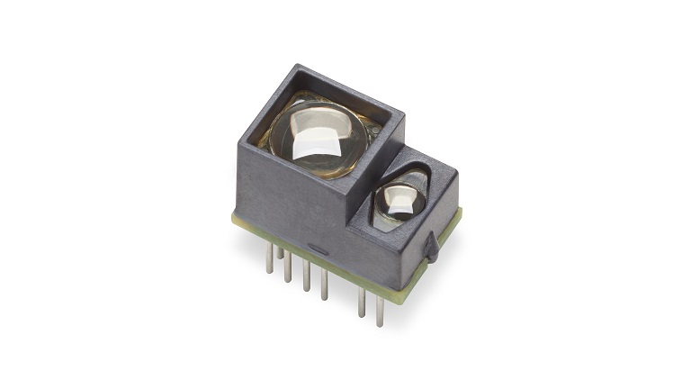
AFBR-S50MV85I is a multi-pixel optical distance and motion measurement sensor module, based on the optical Time of Flight principle
AFBR-S50MV85I is a multi-pixel optical distance and motion measurement sensor module, based on the optical Time of Flight principle. The technology has been developed with a special focus on applications with the need for the highest speed and accuracy at medium distance ranges, with small size and very low power consumption. Due to its best-in-class ambient light suppression, use in outside environments is possible in full sunlight. The sensor accurately measures against white, black, colored as well as metallic and retroreflective surfaces.
Key features
Very Fast Measurement Rates: up to 3 kHz
Operation up to 200 kLux
Multipixel for 3D Motion Detection
Accuracy Error Typically Below ±1%
Additional features
An integrated calibrated clock source
Unambiguous range up to 100 m in 2f mode
Reference Pixel for system health monitoring
Laser Class 1 eye safety ready
Additional Info
The module has an integrated infrared laser light source and an internal clock source. A single power supply of 5.0 V is required. Data is transferred using a digital Serial Peripheral Interface (SPI) using standard 3.3 V CMOS levels. For system health monitoring a Reference Pixel is used in addition to the integrated voltage and temperature sensors. Frame rates of up to 3 kHz are supported, depending on the Microcontroller, the data streaming mode, and the number of evaluated pixels. For frame rates of up to 100 Hz, a dual-frequency (2f) mode is used to achieve an unambiguous range of 50 m in short-range and 100 m in long-range mode.
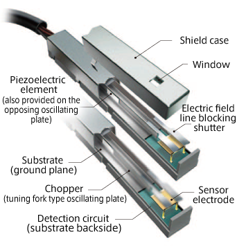
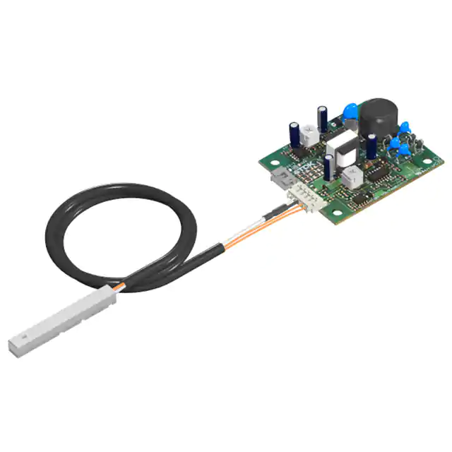
TDK’s EFS series sensors eliminate the effects of disturbances in the electric field intervening between the photosensitive drum and the detection electrode
TDK’s EFS series sensors are feedback surface voltage sensors that support the improved image quality of color copiers and next-generation color printers with the reliability of ±0.05 V or below. The voltage sensors are constructed using high-stability output circuits that feed the detected photosensitive drum surface potential back to the electrical field control chopper and probe shield cover. EFS series sensors eliminate the effects of disturbances in the electric field intervening between the photosensitive drum and the detection electrode. They also show extremely stable and precise output performance where the adverse effects of temperature fluctuations and detection distance (probe positioning) are greatly reduced.
Features:
Reliability of ±0.05 V or lower
Available sensing distance of 1.5 mm to 3.5 mm
In this range, output voltage variation is small and robust output stability can be obtained despite changes in the ambient temperature
Unique optimized structure and circuit design have achieved miniaturization and weight reduction, as well as greater performance in response to market needs
Quick responsiveness of 11 ms which supports high-speed machines
Extremely stable output performance is maintained for long periods of time through accurate driving made possible with the unique structural design and superelastic alloy chopper consisting of the piezoelectric element with optimized conversion efficiency
Quick responsiveness to high-speed and high image quality needs
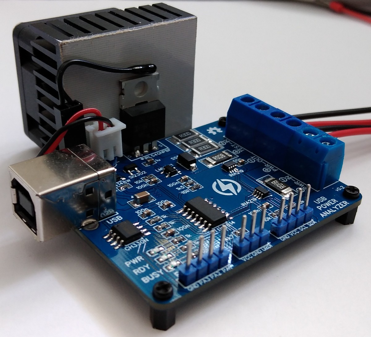
Not sure there is anyone on the internet who loves the Attiny series of microcontrollers as much as Stefan Wagner. We have explored a number of projects from him, from the USB power tester to the TinyRemote with ATtiny13, all based on a member of the Attiny series of microcontrollers. Going over his EasyEDA profile a few days back I noticed another project; the ATtiny814Power Analyzer.
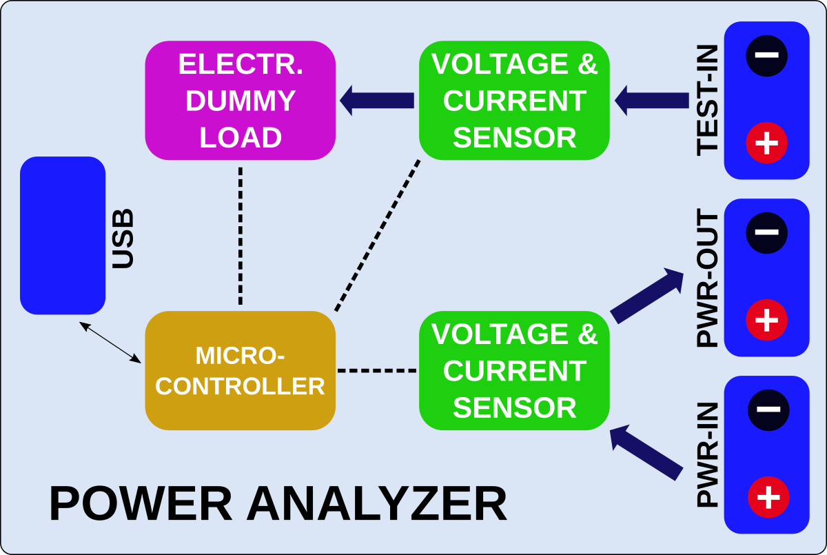
Based on the ATtiny814, the power analyzer is a programmable electronic constant current dummy load with two high side voltage and current sensors for automatic analysis of power supplies, DC/DC converters, voltage regulators, batteries, chargers, power consumers and other related devices. It comes with a USB serial interface through which it can be controlled via a serial terminal software like the serial monitor or the Python-based Software developed by Stefan.
Based on Stefan’s description of the device’s operation, the ATtiny814 controls the electronic dummy load via its internal digital to analog converter (DAC) with all the 5 internal reference voltage being used to get the maximum accuracy and resolution of the DAC. The device features two (2) INA219 current sensors, one of which is used to perform Voltage and Current measurements at a resolution of 4mV/1mA via a high side 8mOhm shunt resistor connected to it, while the other is connected to another 8 mOhm shunt resistor between the PWR-IN and PWR-OUT terminal.
How it works
Via the USB Serial interface, the device can be connected to a PC or a RaspberryPi, and commands can be sent to the Analyzer via a terminal software or by the GUI-based Python script. The Analyzer has different built-in automatic test algorithms and the data/result is sent back via the serial interface/USB to the PC/RaspberryPi to be analyzed by the Python software, or exported to a spreadsheet program for further analysis.
There are several builtin tests that can be performed using the power analyzer, some of the major ones include;
A Load Test
Power Efficiency Test
Voltage Regulation Test
Battery Discharge Test
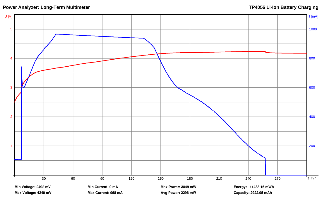
Long Term Multimeter
The heatsink and fan are an important part of the device to prevent a thermal breakdown of the MOSFETs, to ensure they are not overloaded and are in good condition at all times, the ATtiny814 measures the power and temperature of the heatsink, controlling the fan and cutting off the load when the temperature is too high.
Like all Stefan‘s projects, the power analyzer is completely open-source and everything you will need (including schematics, BOM, firmware, PCB designs, and build guides) to build your own version of the device is available on the project’s page here.
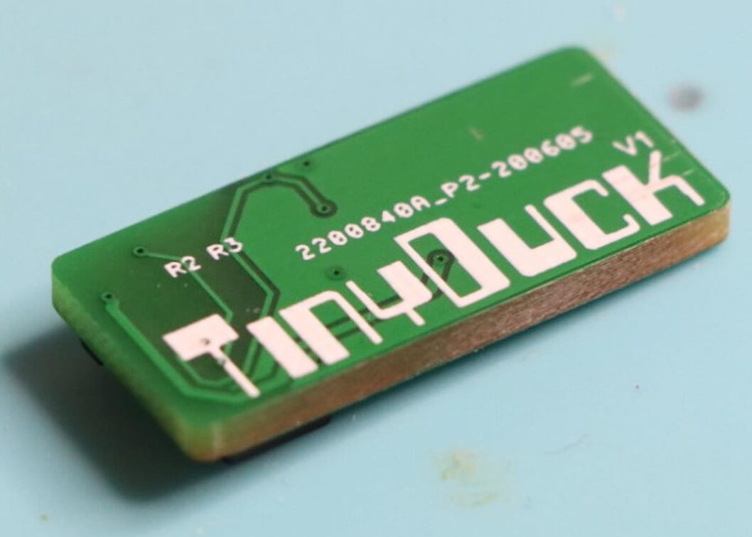
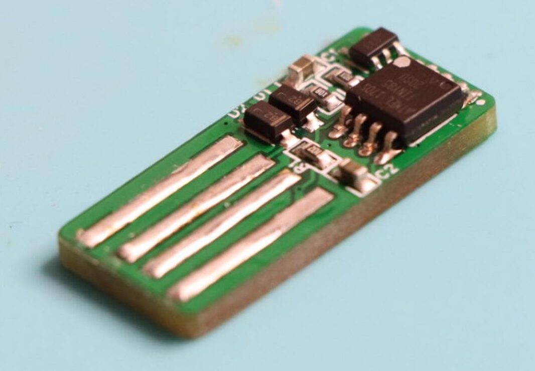
We’ve seen several Security-based hardware projects from Koko (@justcallmekoko) in the past, including the Masterkey keylogger which we explored a few days back. Looking through his projects on GitHub today, I stumbled on another security-based project called the Tinyduck.
A cheap alternative to the popular Rubber Ducky, the Tiny Duck is an Attiny85 microcontroller-based pentest tool that comes in the form factor of a thumb drive, poses as a keyboard to the host computer, and allows the user inject keystrokes at high speeds.
Like the Rubber Ducky and its application in the Mr. Robot series, the tiny duck can be used to execute keystrokes to install backdoors, exfiltrate documents, or capture credentials. It will execute a prewritten script of keystrokes on a target computer as though it were a keyboard so whatever you can do with a keyboard, you can do it faster with the tiny duck and some imagination.
While a lot of similar projects exist on the internet, the goal behind Koko’s project was to make the device as small as possible, and the results speak for itself, as the tiny duck is just about the size of what one could call an overgrown fingernail.
The Tinyduck device works the same way as the Digispark Attiny85 board, right down to the bootloader. So for users who already have the Arduino IDE Set up to work with the Digispark board, the firmware upload process should be quite straightforward. However, the Github page contains guides to set the device up on Arduino IDE, for those who need it.
Like the Rubber Ducky itself, the Tinyduck’s firmware is developed using Ducky Script, which is a straight forward scripting language used to create keystroke injection binaries to be run on the original USB Rubber Ducky. However since the Tinyduck requires the Arduino IDE for firmware upload and Ducky Script is not represented by the IDE, users will have to use one of the several community-developed tools like digiQuack which helps translate Ducky Script into Arduino Code with Digispark specific libraries. Instructions for the conversion process is also available on the Github page.
Speaking on the device’s usage, Koko wrote:
“Tinyduck is intended to be a fire and forget device. Once inserted into a computer, Tinyduck will execute its preprogrammed functions without any needed user intervention. Because of the required USB support, Tinyduck will take 5 seconds to run through the micronucleus bootloader before proceeding to its main code execution”.
More information on the device and guides to building your own version of it can be found on the project’s Github page here.
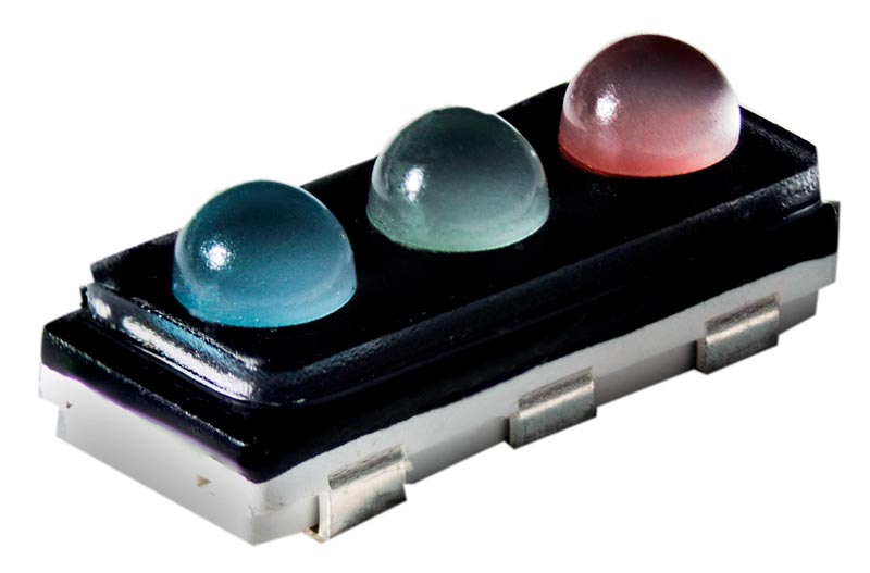
Cree has announced the CV94D-FCC LED that integrates three emitters in a compact surface-mount device (SMD) package. The package includes tightly packed red, green, and blue (RGB) emitters enabling full-color signs or displays based on solid-state lighting (SSL) technology. Cree identified the target application as intelligent transportation systems, with a primary example being dynamically changeable signs that are increasingly being suspended above freeways.
We have written quite a lot of late about LED-based, directly- or self-emissive color displays. Self-emissive means the LEDs deliver the video images as opposed to, say, being used for backlights in a liquid-crystal display (LCD). The technology has long been used in applications such as sports stadium video boards and façades at locations such as Times Square in New York. Finer pixel pitch is even bringing the technology indoors.
In the transportation segment, meanwhile, dynamic signs allow cities and states to deliver important information to drivers. In the US, for example, the signs broadcast what are called Amber Alerts when a child is abducted. They also notify drivers of road closures and lately have been used to display coronavirus reminders.
Most of the freeway signage has been based on amber monochromatic technology. But signs that are either full color, or even that just have a portion of the display capable of color, can do a better job of grabbing attention and expressing a message.
The requirements for such transportation-oriented signage and facade displays share many of the same requirements from RGB LEDs and yet need difference characteristics in some aspects. For example, the tightly packed and aligned LEDs, with each package forming a pixel, ensure good far-field performance in terms of uniformity and precision. In other words, the display looks sharp from afar. Many transportation displays have used discrete, through-hole LEDs in the past and it is far harder to manufacture a precise display with such technology. The integrated RGB emitters also result in better color mixing.
Where transportation display requirements differ considerably from, say, facade displays is in viewing angle. A display board on a building or in a sports stadium needs a very broad viewing angle so as many people as possible can see the images. The freeway sign needs the brightness of the LEDs focused much more narrowly so that drivers can see the sign message from as far away as possible. Cree said the CV94D is the brightest LED on the market with a 30° beam pattern.
The color, beam, and uniformity combine with the ease of manufacturing as benefits for manufacturers of signs. SMD LEDs are assembled on automated printed-circuit board (PCB) assembly lines. And precision is a given.
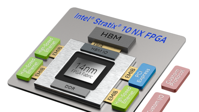
As the immense value proposition of Edge Computing becomes more obvious, Chip manufacturers are working twice as hard to be the one that develops the SOC, FPGA, or MPU that provides designers with all that is needed to develop powerful Edge AI-based solutions. While a lot of progress has been made with MPUs and SOCs via impressive boards like the Google’s Coral and the intel compute stick, there are very few FPGA solutions out there with the kind of specifications required for Edge-AI. Taking a stab at this, Intel recently announced the launch of a new, AI-Optimized FPGA called the Stratix 10 NX.
The Stratix 10 NX is an AI-optimized FPGA, designed for high-bandwidth, low-latency AI acceleration applications. It delivers accelerated AI compute solution through AI-optimized compute blocks with up to 15X more throughput compared to the standard Intel Stratix 10 FPGA DSP Block. It provides an in package 3D stacked HBM high-bandwidth DRAM and up to 57.8G PAM4 transceivers.
The Stratix 10 NX comes with a unique combination of capabilities that provides designers with all that is needed to develop customized hardware with integrated high-performance AI. At the center of these capabilities is a new type of AI-optimized block called the AI Tensor Block, which is tuned for the common matrix-matrix or vector-matrix multiplications used in AI computations, with capabilities designed to work efficiently for both small and large matrix sizes. According to Intel’s spec sheet, a single AI Tensor Block achieves up to 15X more INT8 throughput compared to the standard Intel Stratix 10 FPGA DSP Block.
Asides, the AI Tensor block, the device also implements abundant Near-Compute memory stacks that allow for large, persistent AI models to be stored on-chip, reducing latency with large memory bandwidth, to prevent memory-related performance challenges usually experienced with large models.
To ensure a scalable and flexible I/O connectivity bandwidth and eliminate its limiting effect in multi-node AI inference designs, the device features up to 57.8 Gbps PAM4 transceivers, along with hard IP such as PCIe Gen3 x16 and 10/25/100G Ethernet MAC/PCS/FEC. The flexibility and scalability provided these connectivity solutions make it easy to adapt the device to market requirements.
A highlight of these 3 key features which sets the Stratix 10 NX FPGA apart is provided below;
High-Performance AI Tensor Blocks
– Up to 15X more INT8 throughput than Intel Stratix 10 FPGA digital signalprocessing (DSP) block for AI workloads1
– Hardware programmable for AI with customized workloads
Abundant Near-Compute Memory
Embedded memory hierarchy for model persistence
Integrated high- bandwidth memory (HBM)
High-Bandwidth Networking
Up to 57.8 G PAM4 transceivers and hard Ethernet blocks for high efficiency
Flexible and customizable interconnect to scale across multiple nodes
No price information is available at the moment but more information on the features and applications of the new FPGA can be found on the product’s page on intel’s website.
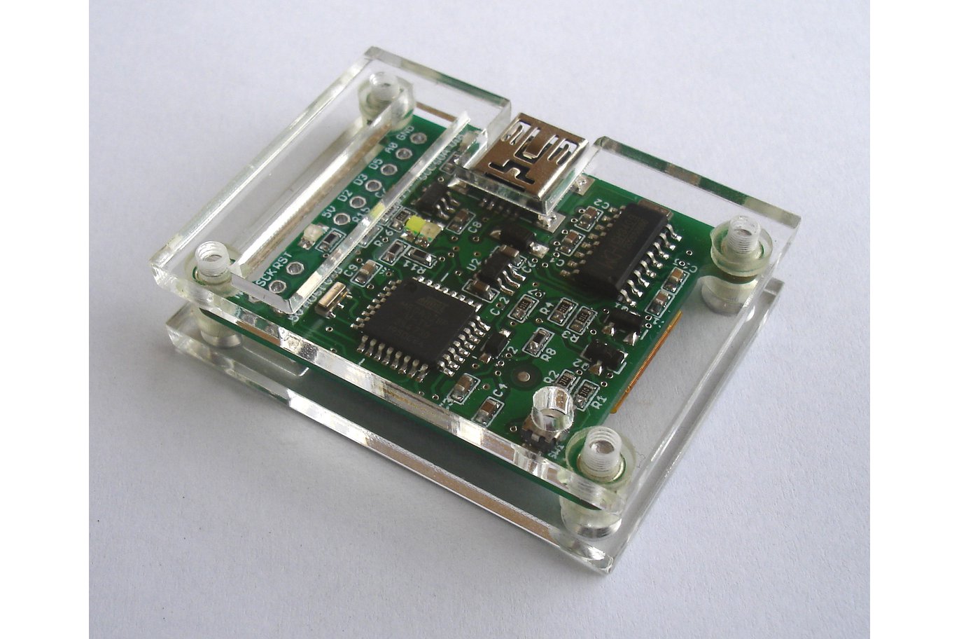
Made popular by the Arduino based on it, the Atmega328p has become one of the most popular microcontrollers around, thanks to the ease with which it can be programmed using the Arduino IDE. Either as a direct clone of Arduino boards like Uno and Nano or as a new board with an entirely different form factor, the number of boards based on the Atmega328p has not slowed down, with each board offering one unique proposition or the other. One of the latest board which has been enjoying a good level of success in recent times is the Atmega328p Board designed by New Zealand based Olabec.
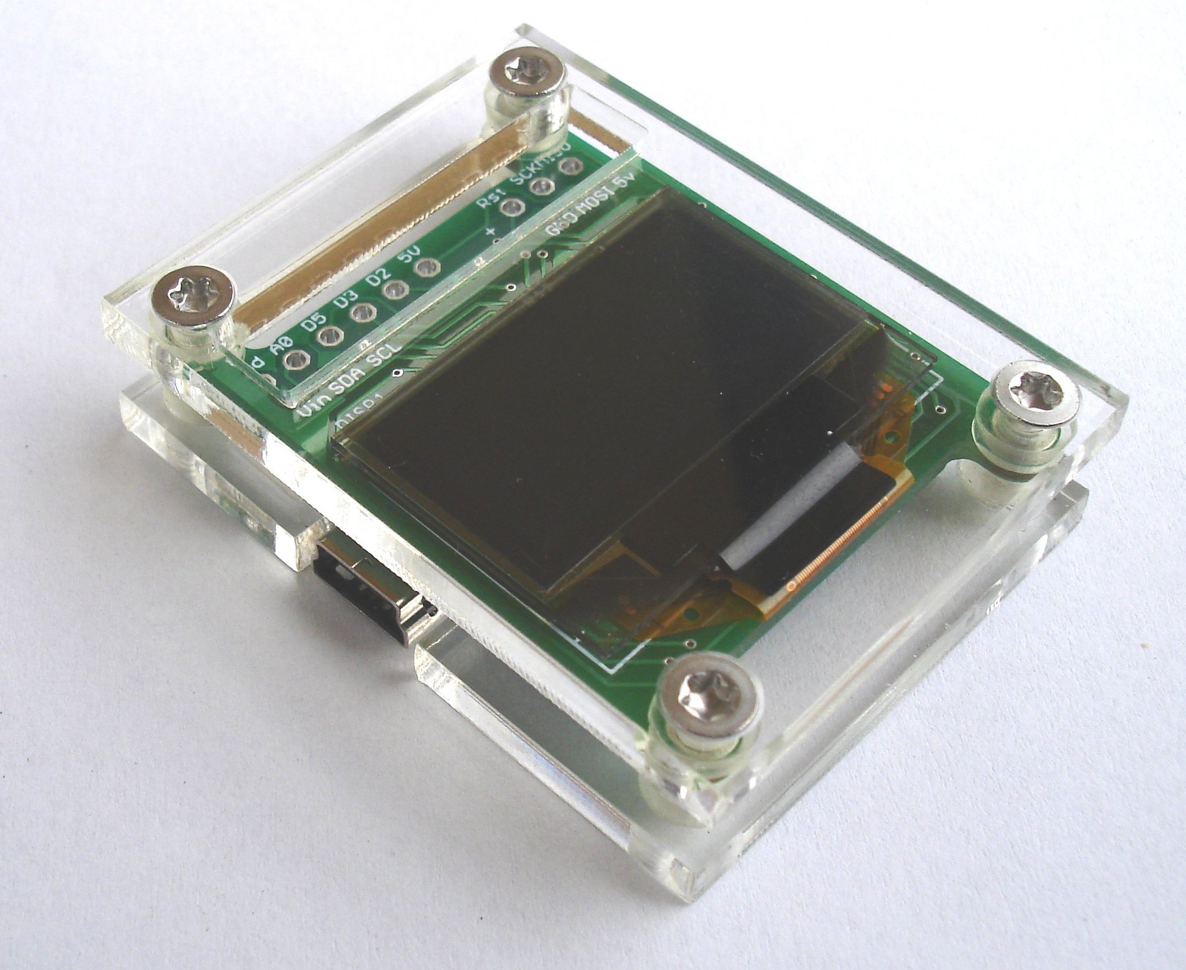
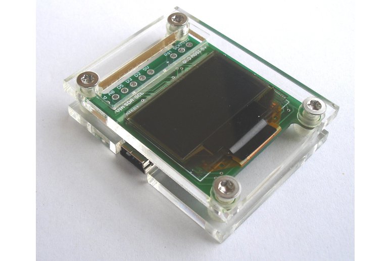
The new board is a small form factor development board based on the Atmega328p microcontroller coupled with a 0.96″ Blue OLED display that is connected to the microcontroller via the I2C bus, ensuring the pins used by the screen can also be used for other sensors or actuators (so far they are based on the I2C communication protocol).
The new board also features an onboard serial UART which eliminates the need for an FTDI converter and makes USB connections/code upload easier. The serial UART on the device is based on the CH340, as such, you will need to have its drivers installed on your PC to be able to program the board. The board is compatible with the Arduino Uno board file so to program it with the Arduino IDE, users should select the Arduino Uno as the board type.
According to Olabec, the new board was designed for convenience. Speaking about the reasons for creating the board, he mentioned that
“Rather than have a separate Uno and display board connected with a bird’s nest of wires, the board and display are ready to use. I have also used a Mini USB connector rather than the fragile micro USB”.
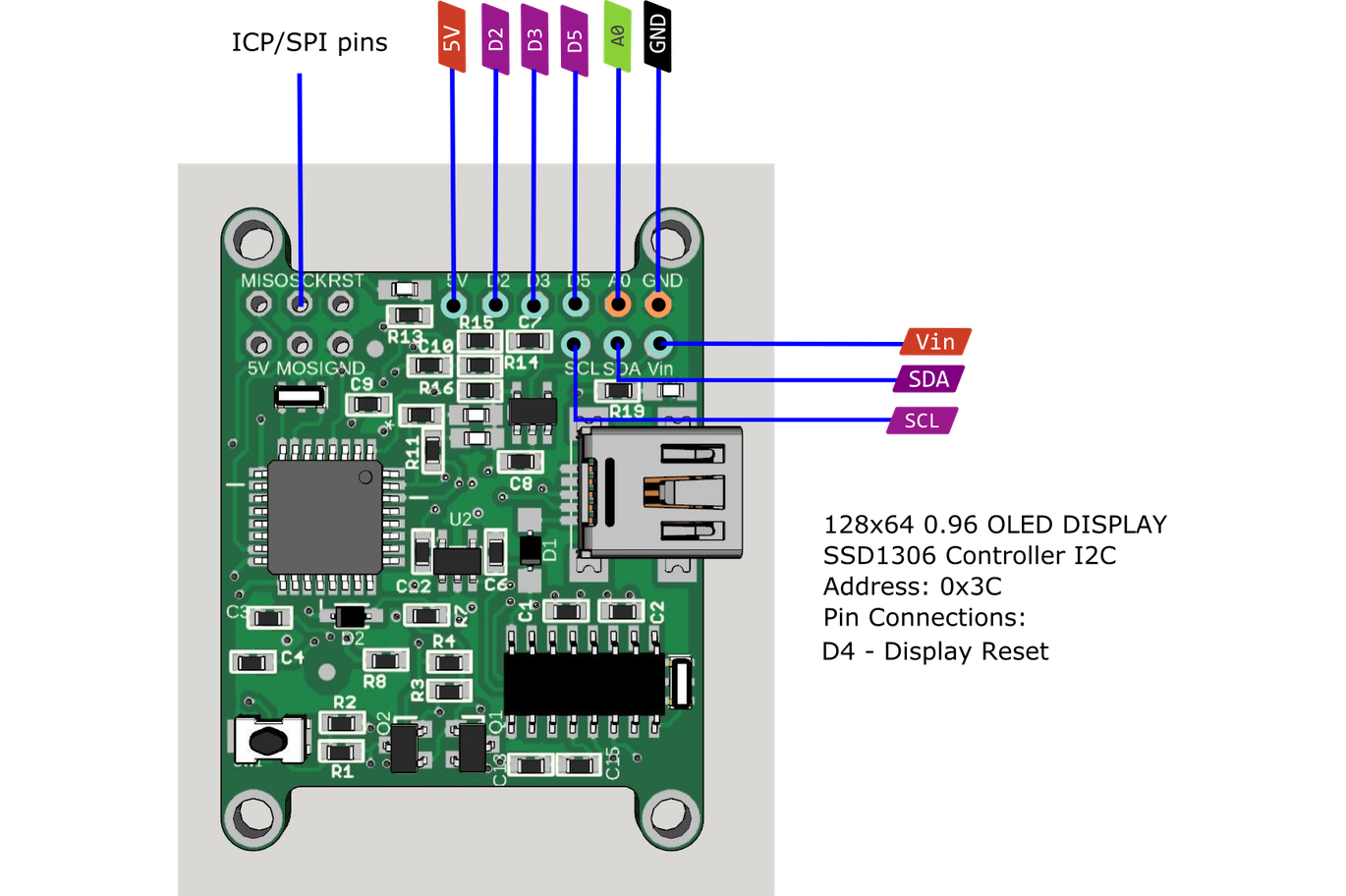
For some reason, not all of the I/O pins of the microcontrollers are available on these boards. The available pins include:
Digital pins – D2,D3,D4,
Analog pins – A0,
i2C pins A4,A5 (SCL,SDA)
SPI pins through the 6 pin ICP header.
The board runs at 5V with onboard LDO 5V and 3.3V regulators, and the maximum input voltage to it’s Vin pin is 16V.
The 30 mm x 40 mm board is currently available for sale on Tindie for $28.00 and it comes with a laser-cut acrylic frame included for protection.
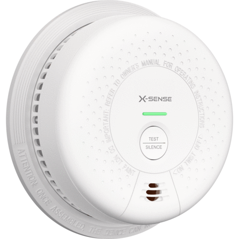
Smoke Alarms are devices that sense smoke as an indication of fire. They are critical to safety in homes and businesses and are required for most property insurance plans. However, these devices exist in different shapes and sizes on the market, with different features incorporated by different manufacturers, in such numbers that it becomes a difficult task for a non-technical person to choose and establish the difference between them. For this reason, we thought it’d be a good idea to lend our voice to the conversation, starting with a review of one of the coolest Smoke detectors out there: the X-sense SD03.
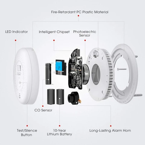
Made by X-sense, which is regarded as one of the most innovative home safety brands, the SD03 Smoke sensor leverages the capacities of an advanced photoelectric sensor combined with the low-power and high-performance features of an ST chipset, to detect dangerous smoke levels from slow-burning and smoldering fires, quickly, in a way that empowers the device to provide the earliest possible warning of fire while minimizing false alarms.
Designed with reliability in mind, the device features routines that ensure the device is active, and is at all times capable of detection and alerts, through an automatic self-check which is performed every 10s. The check evaluates all critical elements including the sensors and battery life to be sure they are in good condition. If an issue is detected, the device notifies the user via beeps and an LED indicator.
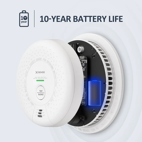
The device was designed for all-round, 24/7 monitoring, as such, it comes with a battery capacity that is certified to comfortably power the device for the estimated product lifespan of 10years, eliminating the challenges users may face with power failure.
An applaudable part of X-sense products is the consideration for the differently-abled and their desire to promote accessibility through products. The X-sense SD03, for instance, comes with 3 LEDs which serves as a way for those with impaired hearing to check the alarm status.
Some technical specifications of the Smoke Alarm include:
Operating Life: 10 years
Power Source: 3 V CR123A lithium battery (non-replaceable)
Sensor Type: Photoelectric
Safety Standards: UL 217, ULC S531, EN 14604:2005
Certification: Kitemark and ETL listed
Standby Current: < 6 µA (avg.)
Alarm Current: < 60 mA (avg.)
Best Operating Ambient Temperature: 40-100 °F (4.4-37.8 °C)
Best Operating Relative Humidity: ≤ 85% RH (non-condensing)
Alarm Loudness: ≥ 85 dB at 10 ft (3 m)
Silence Duration: ≤ 9 minutes
Indicator Light: LED (red/yellow/green)
Color: White
Material: ABS/PC
Installation Method: Screw fixings and mounting bracket supplied
Usage: Indoor use only
Weight: 0.58 lbs (263 g)
Dimensions: 5.7 x 5.7 x 2.0 inches (146 x 146 x 51 mm)
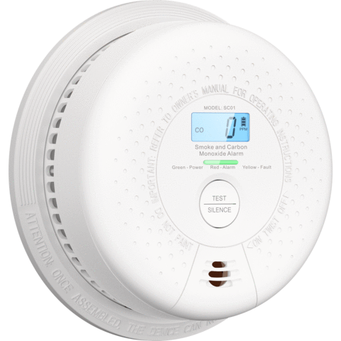
Asides the SD03 Smoke alarm, another interesting Smoke Alarm I found among X-sense’s range of products is the X-Sense SC01 Smoke and Carbon Monoxide Detector.
SC01
The X-Sense SC01 combines all the features of the SD03, including its 10-year battery life,with carbon monoxide detection, and a real-time display of the concentration of CO in the surrounding air, on a built-in LCD.
The 2-in-1 device ensures you get double protection from both invisible, odorless, and deadly CO, and Fire/smoke.
Like the SD03, the SC01 is designed for a 10 years life span and the inbuilt battery is designed to last for that long, removing whatever worry users might have about the performance of the device if a power failure occurs.
Also designed with Accessibility and considerations for the differently-abled in mind, the SC01 also comes with a multicolor LED that provides visual feedback to users.
Some highlight features of the SCO1 include:
Real-time display of accurate CO concentration levels on the LCD.
Detects both CO and smoke levels in the environment.
FIGARO® CO sensor for high sensitivity, accuracy, and reliability.
Extra loud buzzer with over 85 dB volume for guaranteed alarming.
High-capacity lithium battery for 10 years of reliable operation.
Approved by the ETL and BSI.
Some technical specs of the device are provided below:
Operating Life: 10 years
Power Source: 3 V CR123A lithium battery (non-replaceable)
Sensor Type:
Smoke: photoelectric
CO: electrochemical
Safety Standards: UL 217, UL 2034, ULC S531, CSA 6.19-01, EN 14604:2005, EN 50291
Certification: Kitemark and ETL listed
Standby Current: < 6 µA (avg.)
Alarm Current: < 60 mA (avg.)
Best Operating Ambient Temperature: 40-100 °F (4.4-37.8 °C)
Best Operating Relative Humidity: ≤ 85% RH (non-condensing)
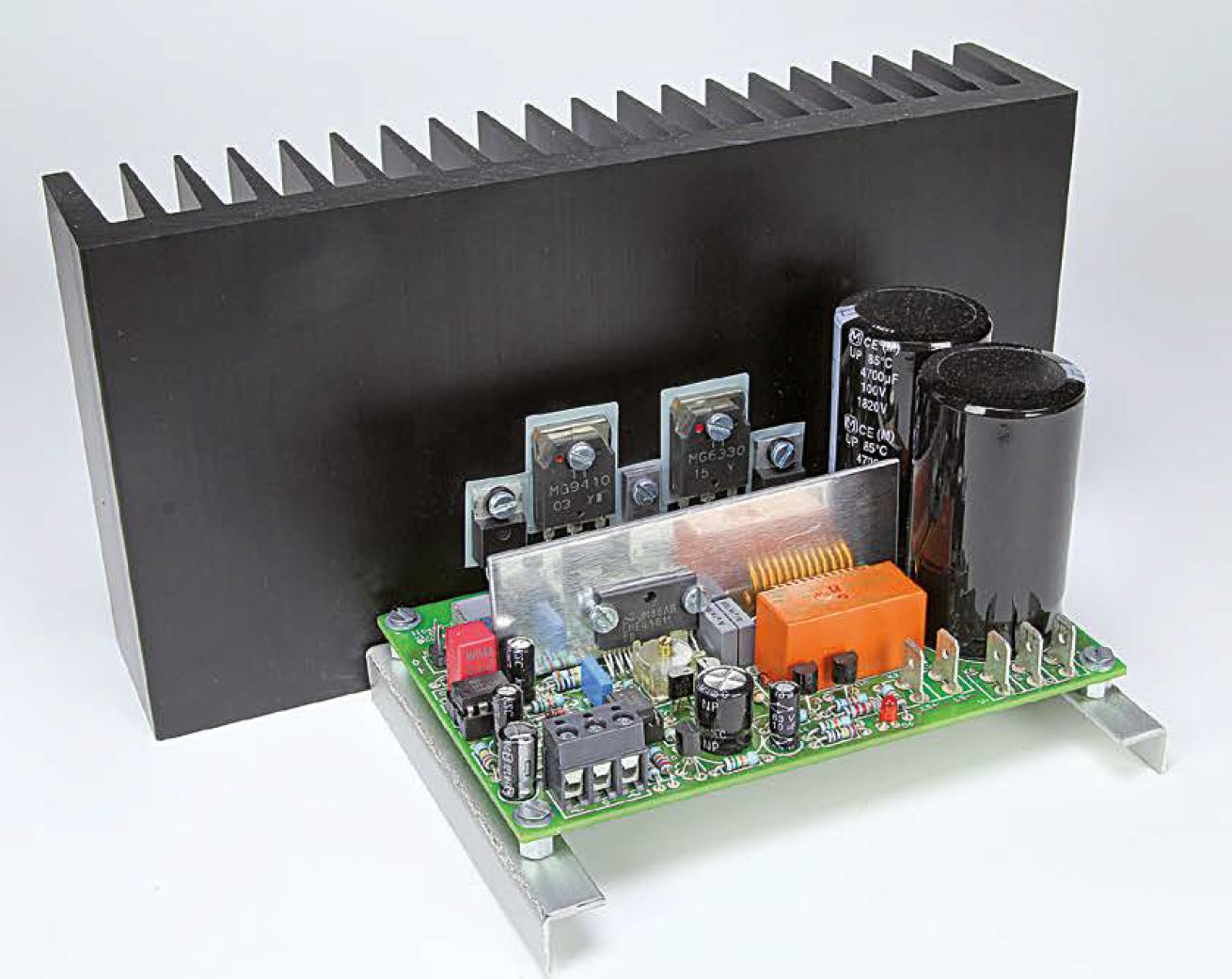
Good news for all audio enthusiasts: we are proud to present yet another all-analog circuit developed entirely in house. Despite the simple design of this audio power amp with just one pair of transistors in the output stage, Q-Watt can deliver over 200 quality watts into 4 ohms with exceptionally low distortion thanks to the use of a special audio driver IC.
Free Elektor Project: Q-Watt Audio Power Amplifier – [PDF]