Arduino, a DIY electronics and microcontroller pioneer, has unveiled its latest offering: the Plug and Make Kit. Designed for beginners, this kit makes it easy to dive into the world of IoT (Internet of Things) without needing prior experience in electronics, soldering, or breadboarding.
What’s in the Plug and Make Kit?
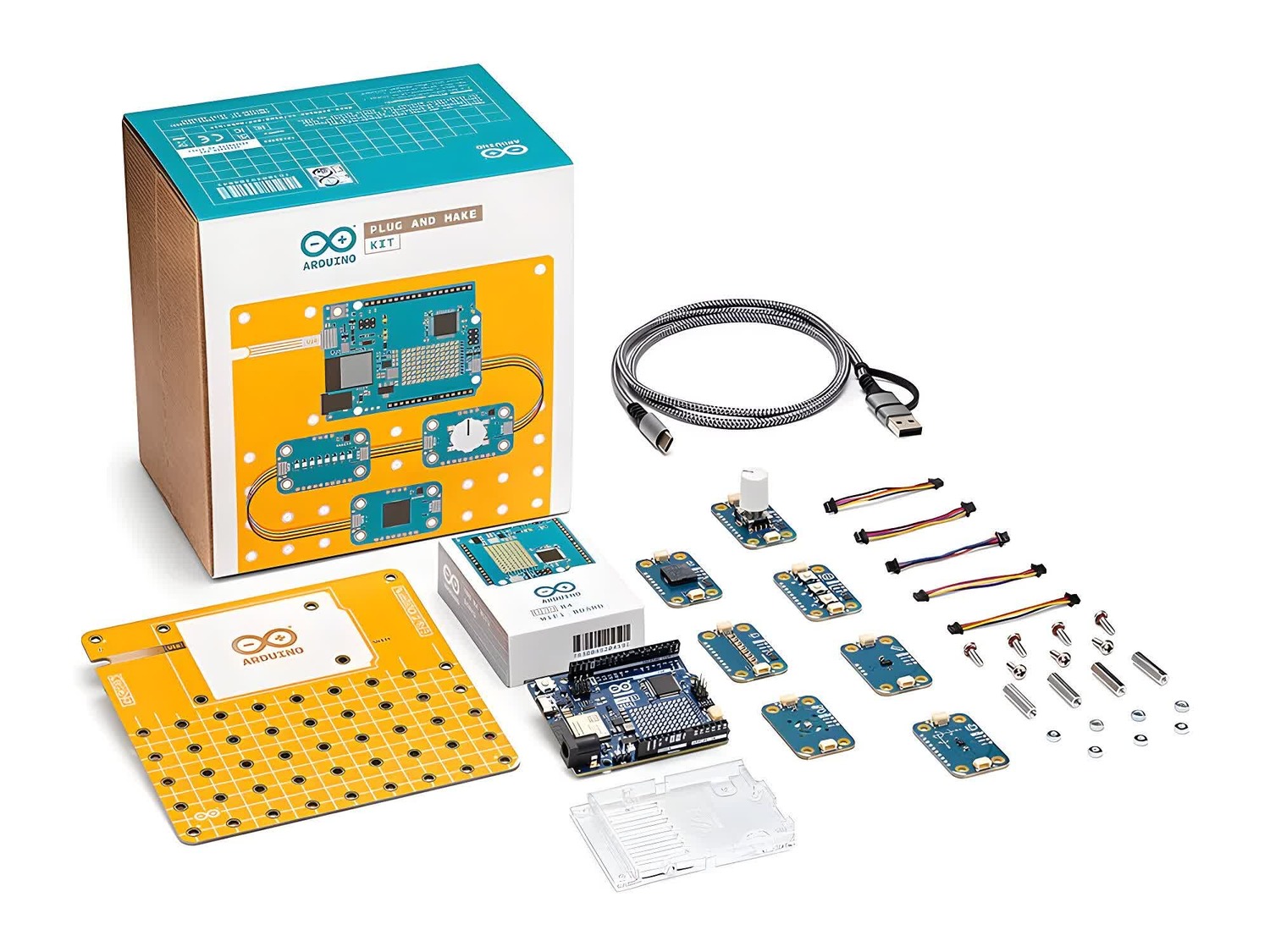
The Plug and Make Kit is a comprehensive package to eliminate the complexities typically associated with electronics projects. Here’s what the kit includes:
Arduino UNO R4 WiFi: The central microcontroller board, featuring a 32-bit processor and WiFi connectivity, serves as the brain of your IoT projects.
Seven Modulino Nodes: These plug-and-play components include sensors and actuators that connect seamlessly to the UNO R4 via Qwiic cables.
Modulino Knob: For precise value adjustments.
Modulino Pixels: An array of eight LEDs capable of shining brightly, dimming down, or changing colors.
Modulino Distance: A time-of-flight proximity sensor for accurate distance measurement.
Modulino Movement: A sensor for capturing pitch, roll, or tilt movements.
Modulino Buzzer: To create alarm sounds or simple tunes.
Modulino Thermo: A sensor that measures both temperature and humidity.
Modulino Buttons: Three buttons for easy project navigation.
Modulino Base: A mounting platform for organizing and securing the various project components.
USB-C Cable with USB-A Adapter: For powering the UNO R4 and uploading code.
Qwiic Cables: To connect the Modulino nodes to the UNO R4 board.
The Plug and Make Kit doesn’t just provide hardware; it also offers a guided learning experience. The kit includes seven starter projects to help users get familiar with the components and build practical IoT devices. Some of the introductory projects include:
A weather report system
A game controller
Smart lighting
Additionally, Arduino’s Cloud platform enhances the learning process by offering a visual sandbox for projects, a library of pre-configured projects, and a smartphone app for monitoring and controlling your IoT devices.
The Plug and Make Kit may seem similar to other products in the space, like Sphero’s littleBits, which popularized the ‘snap and build’ concept in 2014. However, Arduino’s journey to this point has been years in the making. As Arduino founder Massimo Banzi explains,
“Innovation takes time, and you have to wait for the right moment. We started building modular electronics with TinkerKit back in 2006, then moved forward with the EU Project PELARS in 2014, ESLOV in 2016, and now, Plug&Make in 2024.”
For those interested in electronics but unsure where to start, the Plug and Make Kit presents an accessible, user-friendly entry point. Whether you’re looking to create a food pantry inventory system or any other IoT project, this kit provides the tools and guidance needed to bring your ideas to life.
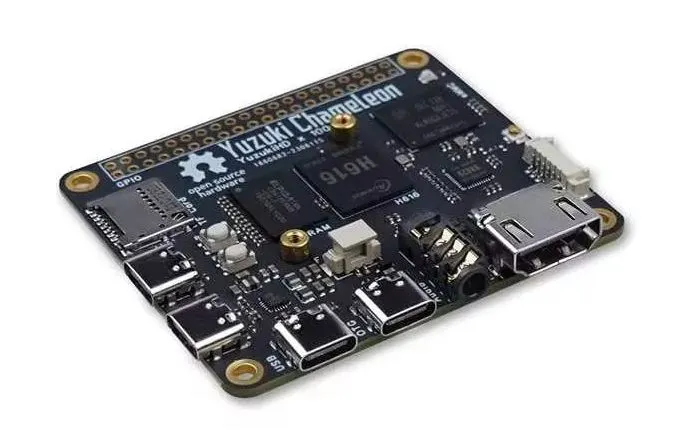
The Yuzuki Chameleon is a single-board computer (SBC) that mirrors the form factor of the Raspberry Pi model A, offering an open-source platform built around the Allwinner H616 chipset. Priced at $25, this board is designed for users seeking a compact yet powerful device for various applications, including media streaming and IoT projects.
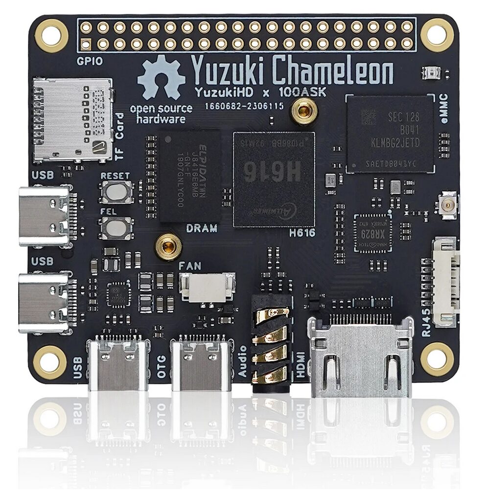
At its core, the Yuzuki Chameleon features the Allwinner H616 System-on-Chip (SoC), which houses a quad-core Cortex-A53 processor and an ARM G31 GPU. This combination allows the board to support up to 2GB of RAM and 128GB of eMMC storage, with additional storage options available via an onboard MicroSD card slot. The H616 chip is tailored for high-quality 64-bit video decoding, supporting 4K@60fps output and integrating Allwinner’s SmartColor3.3 picture enhancement engine, along with Dolby and DTS audio processing, making it a strong candidate for multimedia projects.
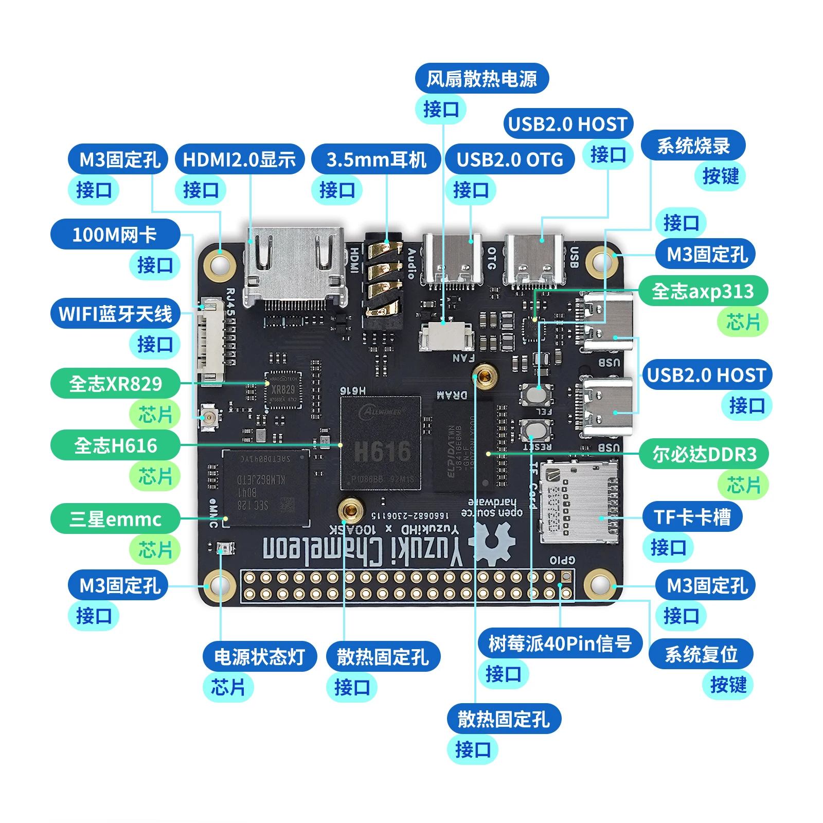
Connectivity on the Yuzuki Chameleon is robust, with an XR829 chip providing Wi-Fi and Bluetooth capabilities. The board is equipped with four USB Type-C ports (three for HOST and one OTG) that allow connection to peripherals such as USB cameras and capture cards. Additionally, it includes a 100M Ethernet interface and a 40-pin GPIO header, which facilitates expansion with SPI LCDs, Gigabit Ethernet, microphone arrays, and various sensors. To ensure effective cooling, the board is designed with a fan connector and radiator fixing holes, and power management is controlled by the AXP313A PMIC chip.
The Yuzuki Chameleon supports a variety of firmware options, including Tina Linux, Ubuntu, and Android TV, with the latest firmware versions accessible through the project’s release page. Developers can easily set up a development environment using the provided BSP, available as a Docker image. The board is also compatible with firmware flashing using Allwinner’s proprietary tools like PhoenixSuit, as well as mainline Linux distributions such as Armbian and Ubuntu, which are well-documented in their GitHub repository. This versatility and support for multiple operating systems make the Yuzuki Chameleon a flexible tool for developers and hobbyists alike.
The Yuzuki Chameleon board first appeared on Hackaday in 2022, though it lacked a dedicated product page at the time.
Recently, DongshanPI highlighted the board on Twitter, announcing its availability for purchase with 1GB DDR3 RAM and 8GB eMMC storage for $25.08 on AliExpress.
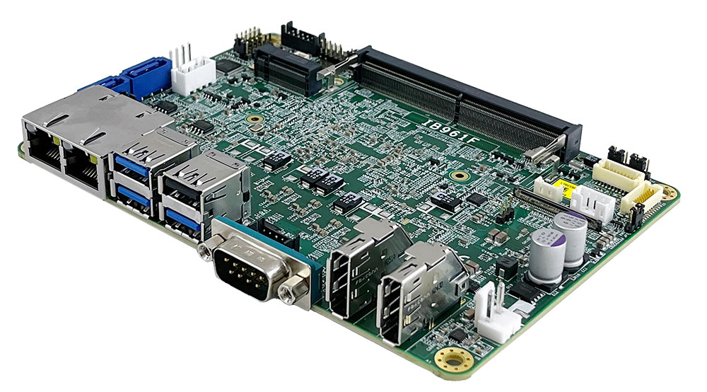
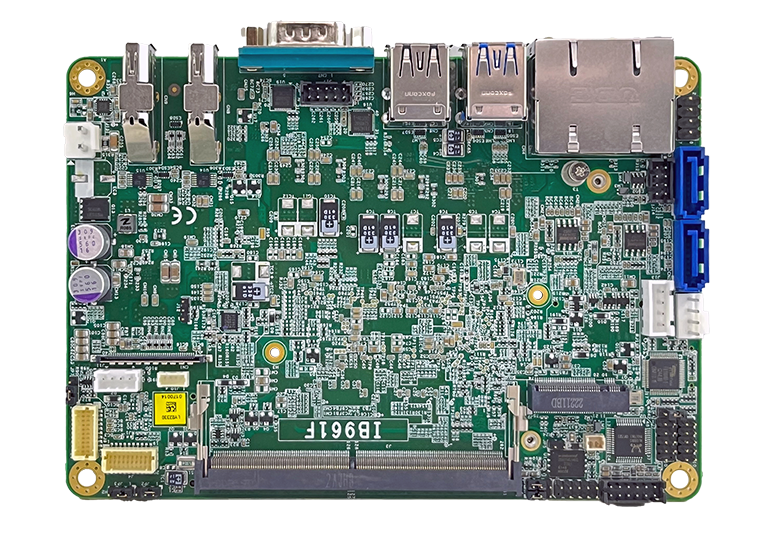
Last month, iBASE Technology introduced a new x86-based 3.5″ Single Board Computer powered by 13th Gen Intel® Core™ processors. The IB961 3.5″ SBC, measuring 102mm x 147mm, suits a range of embedded applications.
The IB961 3.5″ SBC offers several 13th Gen Intel® Core™ options, including the i7-1370PRE, i7-1370PE, i5-1340PE, i5-1335UE, and i3-1320PE. These processors feature a hybrid architecture with up to 6 Performance cores (P-cores) and up to 8 Efficient cores (E-cores). A DDR5-based SO-DIMM slot with a 32GB capacity provides high memory density in a compact form factor. Storage is handled via an M.2 interface (M2280), optimized for NVMe drives. The AMI BIOS ensures reliable and customizable firmware management.
IB961 3.5″ SBC has extensive connectivity options
The IB961 3.5″ SBC delivers robust performance and versatile connectivity through various expansion options. It features three M.2 slots for different functionalities. The M-Key (Type 2280) slot supports NVMe drives with PCIe (4x) signals for high-speed storage. The E-Key (Type 2230) slot supports CNVi for wireless connectivity, and the B-Key (Type 3052) slot supports 5G/LTE modules.
The 13th Gen Intel® Core™ mobile processor with integrated graphics powers the video outputs. The board offers multiple video outputs via two DisplayPort 1.2 interfaces, with additional support for eDP and LVDS. Dual Ethernet ports feature Intel® I226LM and I226V controllers.
The board includes three USB 2.0 ports (one Type-A and two via pin headers) and three USB 3.2 Type-A ports for peripheral connectivity. Whereas, it also has two SATA III ports for external storage. The audio is managed by the built-in HD audio capabilities of the chipset, but this is enhanced by the ALC888S codec for high-quality sound output. The system includes a Fintek F81804U-I I/O chipset for additional interface control, two COM ports for serial communication, and digital I/O with 4 inputs and 4 outputs for versatile device control.
IB961 3.5″ SBC is built for embedded environments
Note that the IB961 3.5″ SBC consumes 7.66 amps on a 12V power supply when equipped with an Intel® Core™ i7-2600 processor and 2x 2GBDDR3-1333 memory. Although it has relatively high power consumption for its size, the board compensates with a wide operating temperature range from -40°C to 75°C.
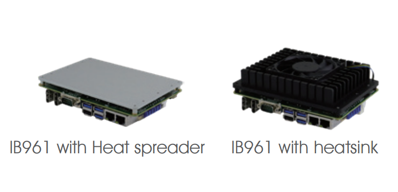
The IB961 3.5″ SBC by IBASE Technology, powered by 13th Gen Intel® Core™ processors, combines robust performance, flexible memory and storage options, and extensive connectivity in a compact form factor. It operates in extreme temperatures. Although iBase technology hasn’t announced sales information for the board, more details are available on its product page. The box also includes an optional heatsink and heat spreader, as noted on the website.
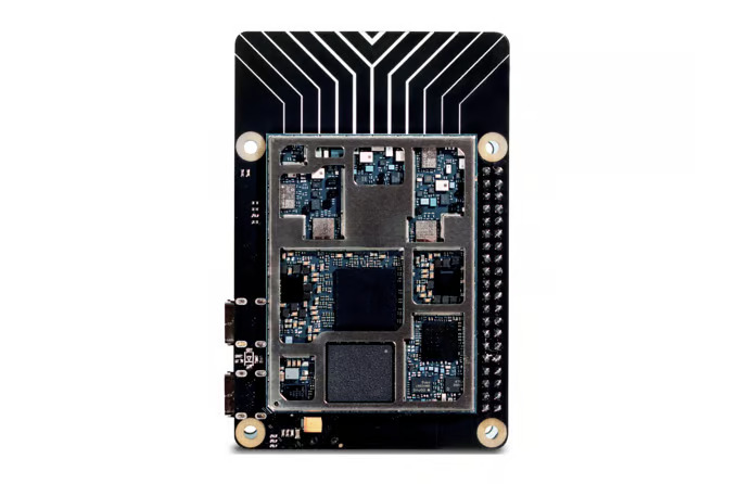
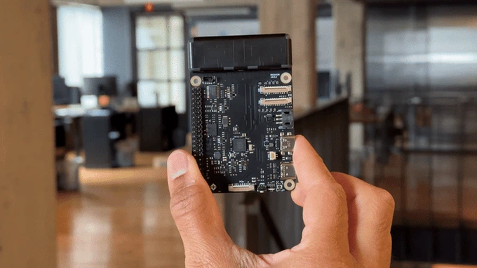
Recently, Particle, a company that designs IoT microcontrollers started a Kickstarter campaign for a high-performance single-board computer (SBC) built for software convenience. Tachyon by Particle is a 5G-connected SBC.
Unlike Particle’s Electron, which has an STM32F205ARM Cortex M3 microcontroller, the Octa-core Qualcomm Snapdragon QCM6490 SoC powers the Tachyon SBC. It also includes an Adreno 643 GPU and an NPU with up to 12 TOPS in performance. The NPU is contained within a Qualcomm Hexagon 770 DSP. 4GB RAM and 64 GB UFS storage support these chip specs—this cumulation of features enables its application in complex AI projects.
With the chipset capable of supporting 4K displays and running powerful AI/ML models, Particle has also included two 4-lane CSI interfaces with ISP, supporting over 20 pre-integrated camera sensors like the IMX519, OV13850, and other computer vision sensors up to 25 megapixels. A 4-lane DSI interface can drive displays with resolutions up to 1200 x 2520. Additionally, the chipset features a USB-C 3.1 PD port with DisplayPort and two PCIe Gen 3 interfaces for high-speed connectivity. Alternatively, the USB-C 3.1 PD port can be
Considering its wireless interfaces, Tachyon is equipped with a WiFi 6E module and is 5G sub-6GHz compatible, capable of operating up to 2.5 Gbs. The SBC also has a built-in antenna but there isn’t more available on its specs. The SBC is embedded with EtherSIM (making it 5G-compatible).
Tachyon also features a Raspberry Pi-compatible 40-pin connector, allowing seamless integration with various optional peripherals, while supporting cameras, displays, and PCIe peripherals connected via ribbon cables. You can easily incorporate off-the-shelf components, Raspberry Pi HATs, or build Tachyon into a custom PCB. Tachyon handles diverse peripheral configurations, ensuring robust flexibility for your projects.
Taychon’s Software Support is Holistic
Tachyon has extensive software support. At the core of this experience is Ubuntu Desktop 24.04 from Canonical. Ubuntu’s reputation for user-friendly design and strong community support makes it an ideal choice, providing a familiar and intuitive desktop environment for Mac and PC users. Additionally, access to Debian’s extensive software repository ensures that all necessary tools are readily available.
For headless applications, Tachyon also supports a headless Ubuntu build, featuring A/B partitions to facilitate atomic OS upgrades in the field. This ensures reliable and seamless updates, even in remote deployments.
Recognizing the needs of advanced users, Tachyon also supports the Yocto Project, offering a highly customizable environment for those who require a more controlled Linux distribution. For superusers seeking further flexibility, Tachyon’s chipset supports a wide range of operating systems, including upstream Qualcomm Linux, Android 13, and Windows 11, allowing users to tailor their systems to specific requirements.
Furthermore, Tachyon includes Particle’s IoT platform which has an edge-to-cloud infrastructure that provides a comprehensive solution for deploying IoT devices, offering device management, OTA software updates, connectivity management, and data automation.
Particle’s Tachyon SBC is the size of a Raspberry Pi with the performance of a mid-range smartphone. More information on the product and its campaign is available on the Tachyon Kickstarter page.
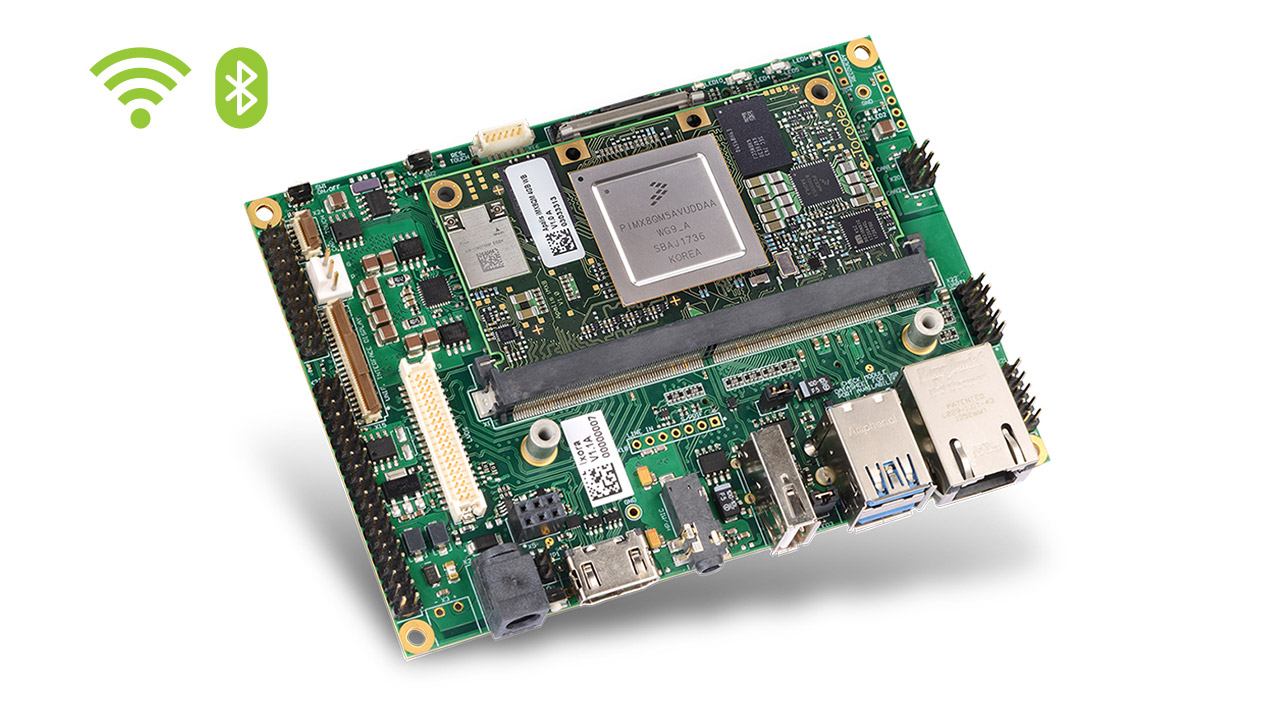
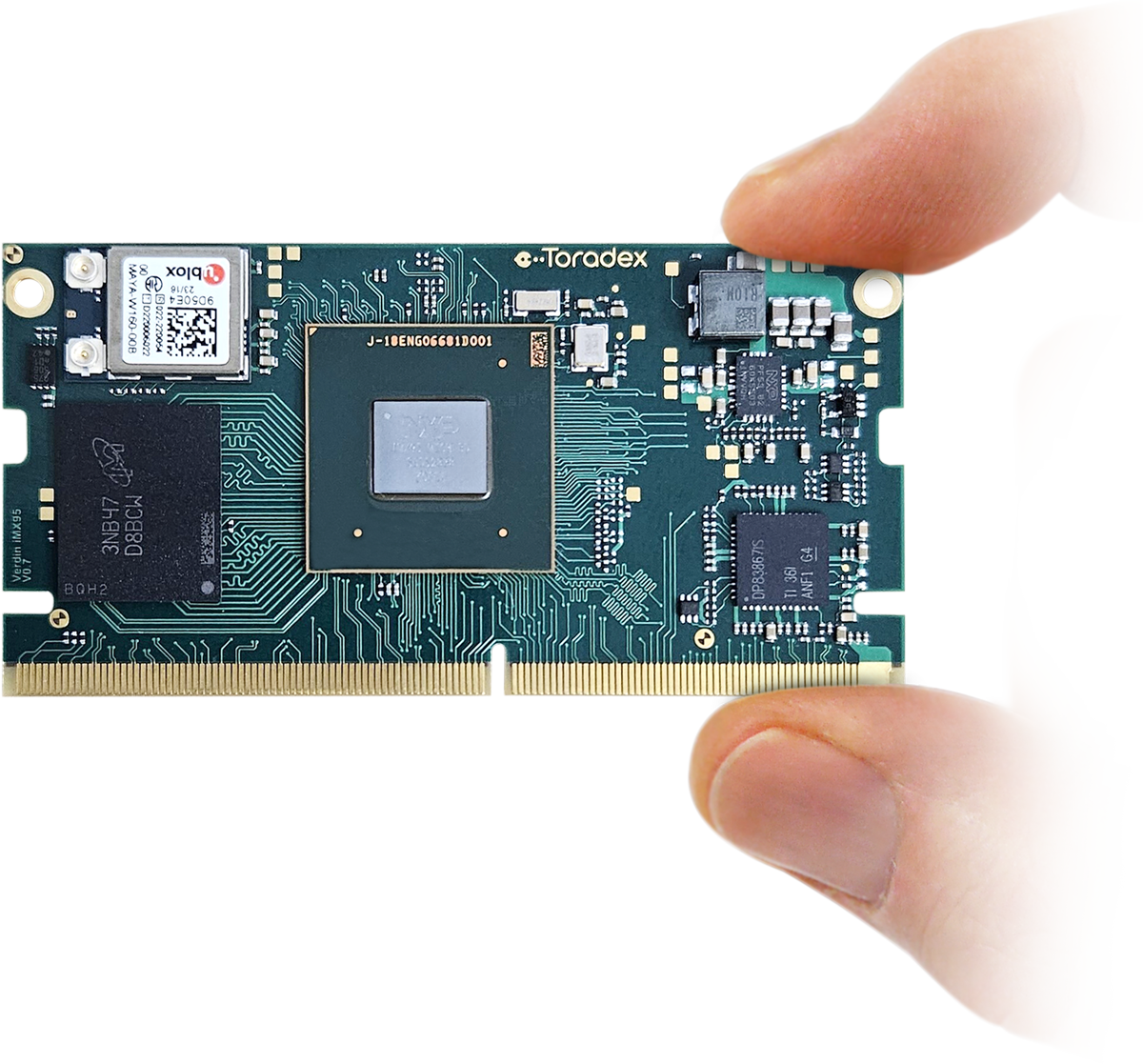
Toradex, a global leader in embedded computing solutions, is excited to announce the launch of the Aquila iMX95 System on Module (SoM), the second in our new and powerful Aquila family of SoMs.
Toradex, recognized as an NXP Platinum partner and the exclusive Alpha program partner for the i.MX 95 SoC, is already shipping the i.MX 95 Verdin Evaluation Kit (EVK). The Aquila iMX95 System on Module, based on the NXP i.MX 95 SoC, combines superior processing power with advanced features, continuing our commitment to delivering top-tier solutions in embedded computing. The module is out-of-the-box compatible with Torizon, an easy-to-use Industrial Linux Platform, which accelerates your products’ development and maintenance.
“The introduction of the Aquila iMX95 to our powerful Aquila Family of SoMs enhances our product line with superior performance and versatility, ensuring that our customers can tackle their most demanding projects with ease. We’re excited to bring this new SoM to the market and continue supporting our community with high-quality, reliable products.” said Samuel Imgrueth, CEO, Toradex.
Aquila iMX95
The Aquila iMX95 SoM combines the full capabilities of the i.MX 95 SoC with Toradex’s proven technology. This module is designed to seamlessly integrate with Toradex’s existing product lines.
Key features include:
A 400-pin board-to-board connector, which provides access to i.MX95 SoC interfaces that are otherwise not available, like the 10 GbE and 2x PCIe ports
Pure compute performance from the 6xA55 cores coupled with LPDDR5 memory (6400MT/s) opens up new possibilities for enhanced multitasking, faster data processing, smoother graphics, and quicker load times
The LPDDR5 memory with support for up to 8x cameras allows developers to get creative with image stitching and environment mapping applications
High-speed networking with a 10 gigabit ethernet interface in addition to the usual 2x gigabit ethernet, all with TSN capability
Expansion possibilities to multiple peripherals such as high-speed storage, connectivity, and networking enabled by 2 separate instances of PCIe Gen3 (x1 lane)
Seamless Performance Scaling: The Aquila iMX95 offers full pin-to-pin compatibility with other Aquila SoMs, facilitating easy scaling of projects. For more demanding applications, performance options extend up to the Aquila AM69
Toradex is dedicated to supporting developers with detailed design documentation and customization services. For projects requiring higher volumes or specific form factors, Toradex offers chip-down services to design, manufacture, and maintain the i.MX95 SoC in bespoke configurations.
For further details on the Aquila iMX95 and to access design documentation, please visit our website or contact our support team.
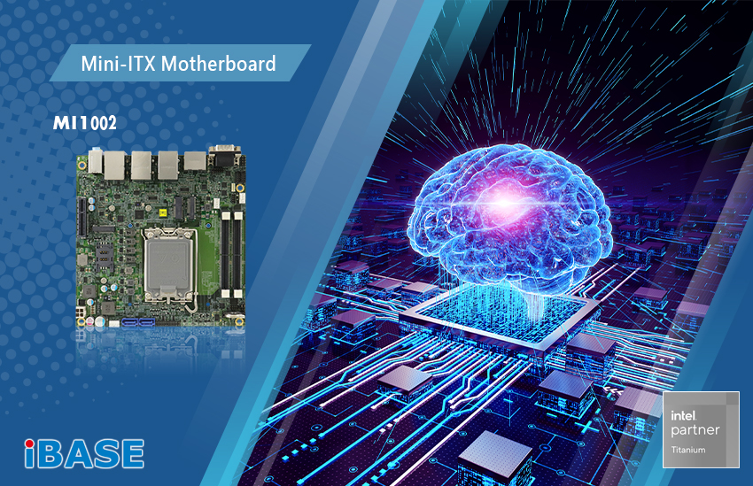
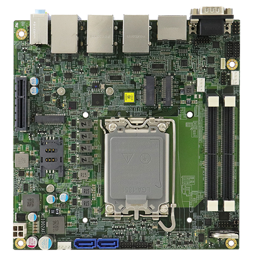
Powered by Intel® Core™ Ultra (Meteor Lake-PS) Processors
IBASE Technology Inc. (TPEx: 8050), a leading innovator of embedded computing solutions, announces the launch of the MI1002 Mini-ITX motherboard powered by the latest Intel® Core™ Ultra processors Series 1 (Meteor Lake-PS platform) with an LGA1851 socket. The new platform provides advanced AI capabilities, enhanced graphics, and remarkable energy efficiency, enabling the MI1002 to handle complex tasks effortlessly, whether deploying AI applications, managing edge computing, or driving IoT solutions.
The MI1002 is available in two variants, MI1002AF and MI1002AF-1, both equipped with two DDR5 memory sockets, multiple M.2 slots for ultra-fast storage and 5G connectivity, and dual 2.5G LAN ports for high-speed networking. The MI1002AF includes support for Intel® iAMT 18.0 and dTPM 2.0, which are essential for enhanced security and remote management capabilities. The MI1002AF-1, on the other hand, is equipped with fTPM 2.0, providing a more cost-effective solution for applications where Intel® iAMT is not required.
MI1002 FEATURES:
Intel® Core™ Ultra processors Series 1 (formerly Meteor Lake-PS)
2x DDR5 SO-DIMM, Max. 64GB
Supports HDMI, DisplayPort(DP++), 2x Type-C
1x Intel® I226LM 2.5G LAN, 2x Intel® I226V 2.5G LAN
4x USB 3.2, 2x USB Type-C, 4x USB 2.0, 4x COM, 2x SATA III
The motherboard features 12V~24V DC input, boosting flexibility and stability in power management across various operational environments and suitable for industrial applications where power sources can vary significantly. It offers a comprehensive range of I/O options, expansion capabilities, and HDMI, DisplayPort, and Type-C ports to accommodate diverse display configurations. With these features, the MI1002 series provides a versatile and scalable solution for a wide array of embedded computing applications, ensuring that users can adapt to rapidly evolving technological demands.
Market leader in solid-state, micro speaker technology brings revolutionary air cooling to ultraportable devices for uncompromised performance in AI and other demanding mobile applications.
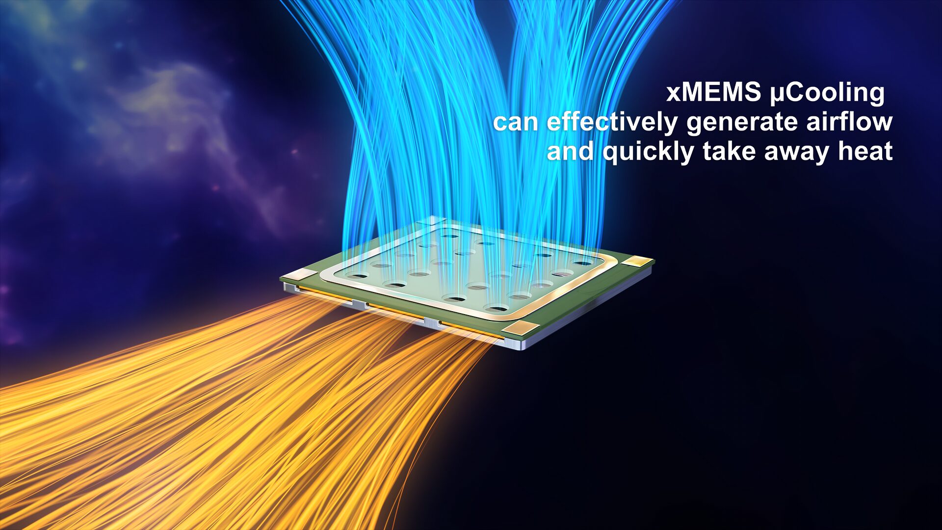
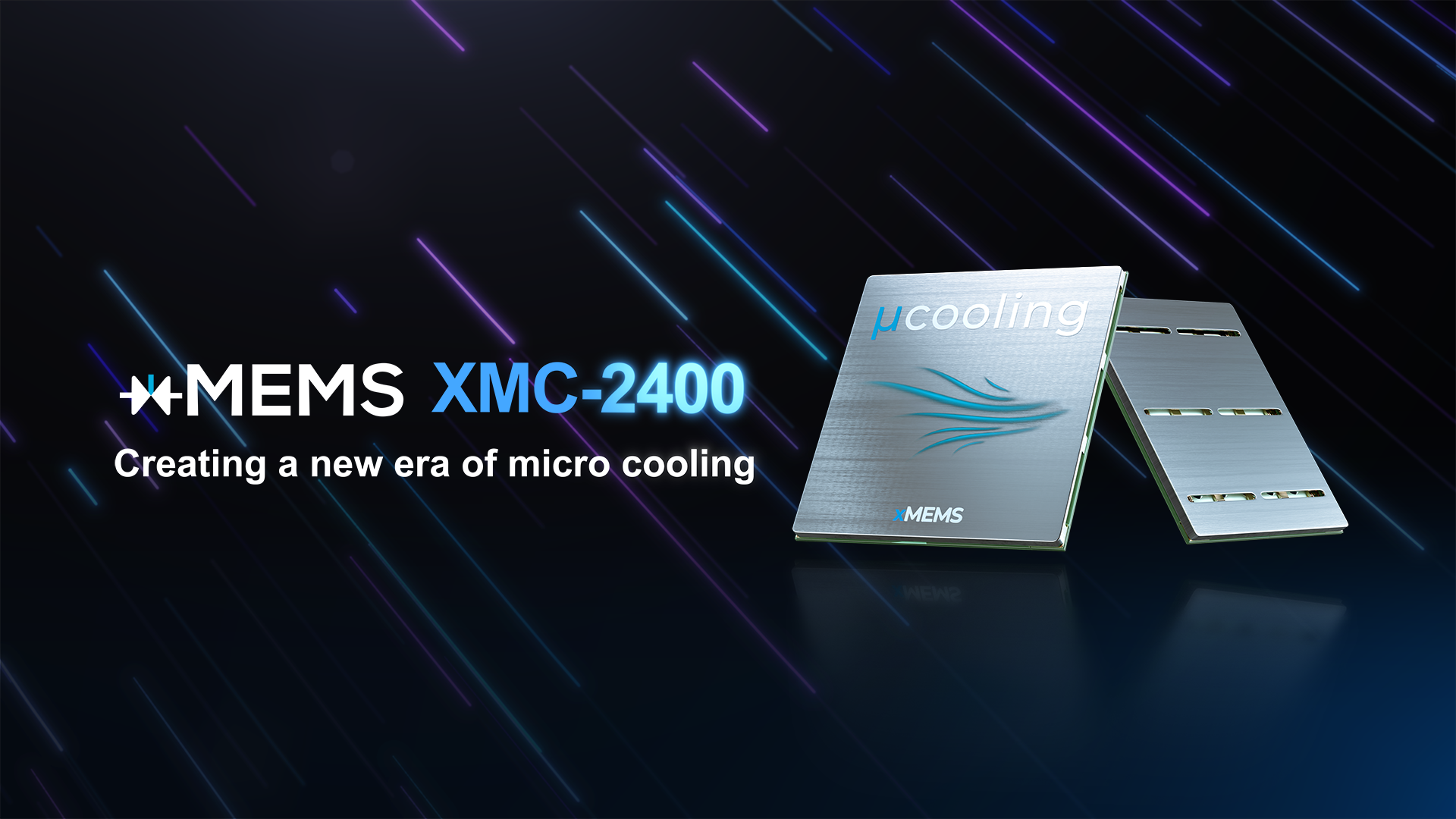
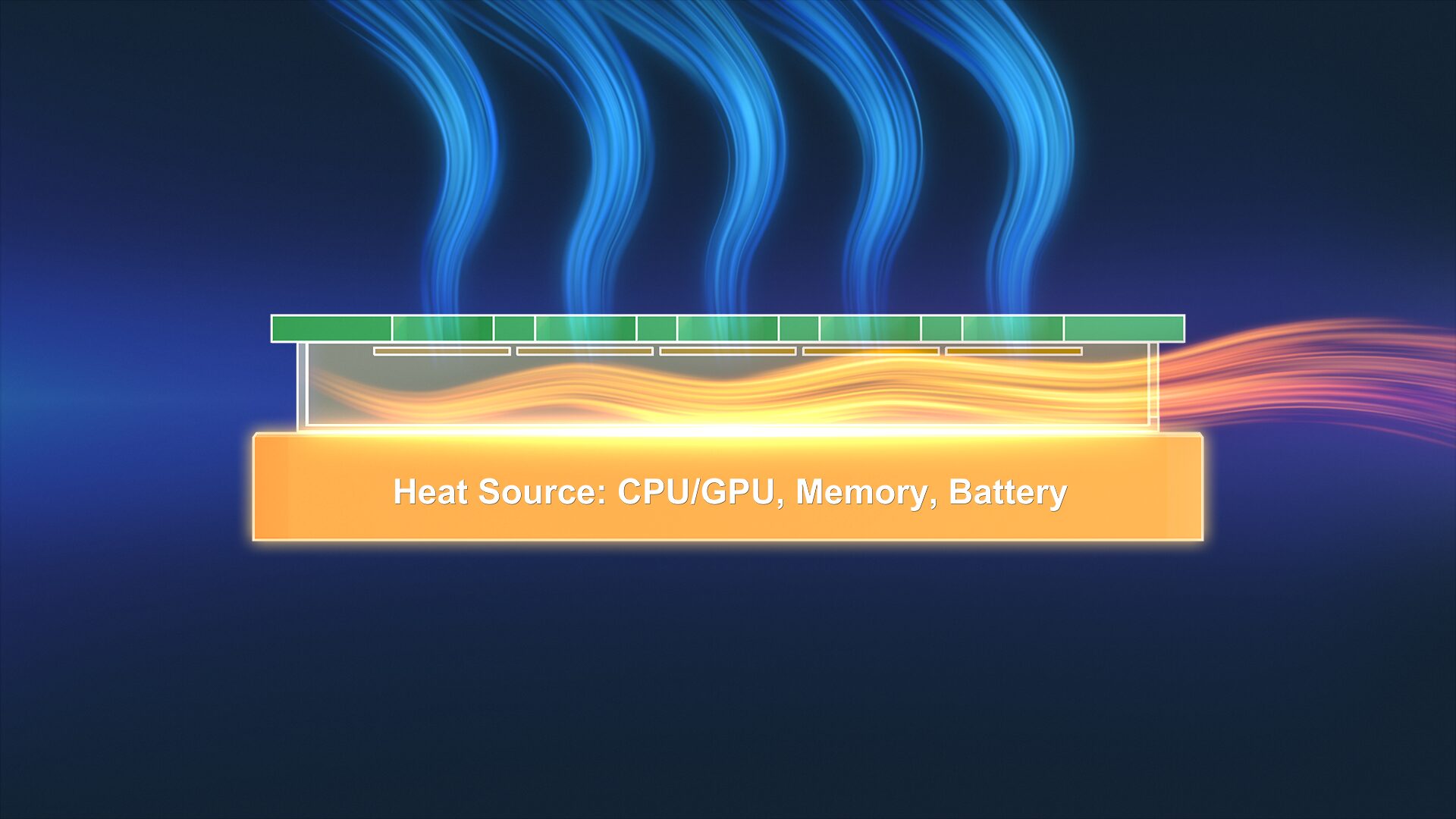
xMEMS Labs, developers of the foremost platform for piezoMEMS innovation and creators of the world’s leading all-silicon micro speakers, today announced its latest industry-changing innovation: the xMEMS XMC-2400 µCooling™ chip, the first-ever all-silicon, active micro-cooling fan for ultramobile devices and next-generation artificial intelligence (AI) solutions.
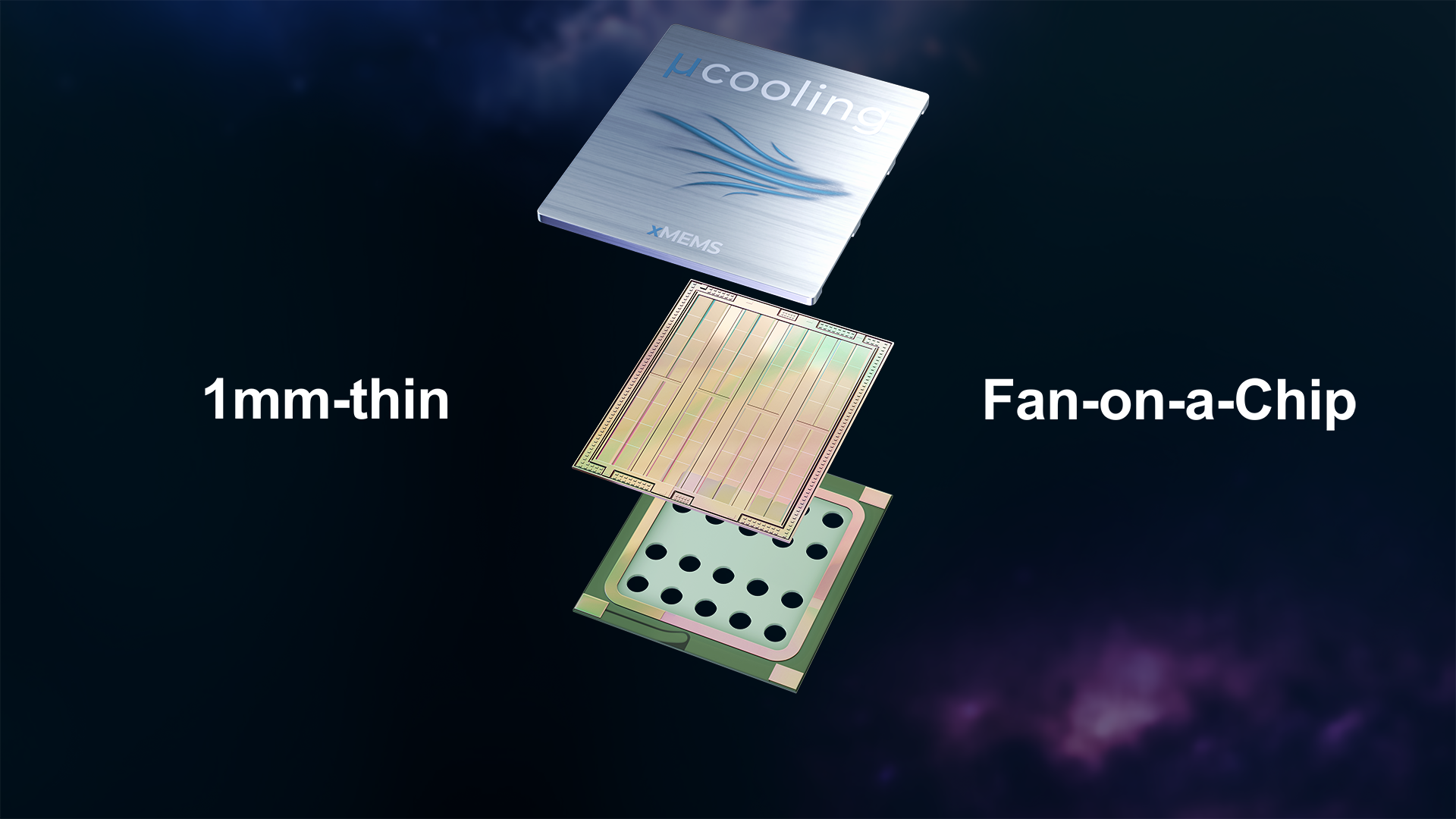
For the first time, with active, fan-based micro-cooling (µCooling) at the chip level, manufacturers can integrate active cooling into smartphones, tablets, and other advanced mobile devices with the silent, vibration-free, solid-state xMEMS XMC-2400 µCooling chip, which measures just 1-millimeter thin.
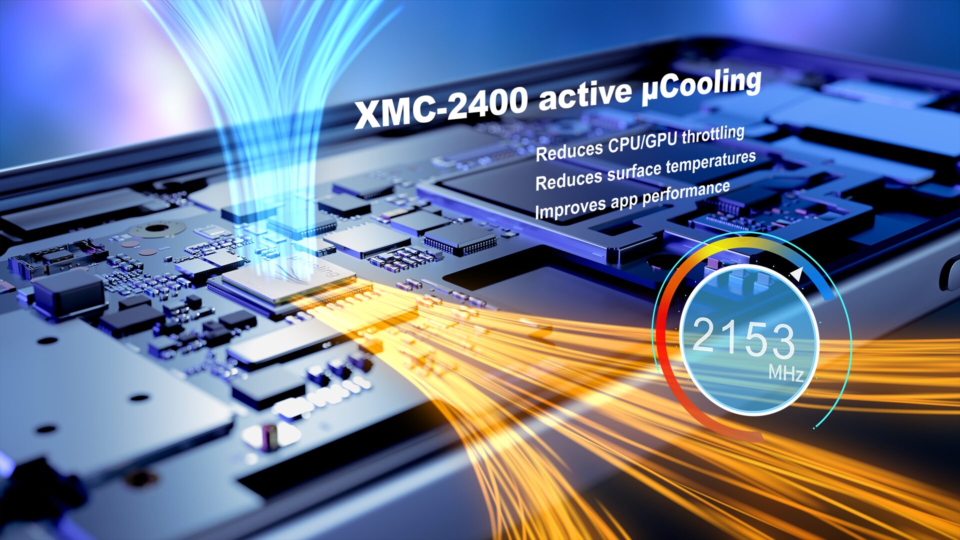
“Our revolutionary µCooling ‘fan-on-a-chip’ design comes at a critical time in mobile computing,” said Joseph Jiang, xMEMS CEO and Co-Founder. “Thermal management in ultramobile devices, which are beginning to run even more processor-intensive AI applications, is a massive challenge for manufacturers and consumers. Until XMC-2400, there’s been no active-cooling solution because the devices are so small and thin.”
The XMC-2400 measures just 9.26 x 7.6 x 1.08 millimeters and weighs less than 150 milligrams, making it 96 percent smaller and lighter than non-silicon-based, active-cooling alternatives. A single XMC-2400 chip can move up to 39 cubic centimeters of air per second with 1,000Pa of back pressure. The all-silicon solution offers semiconductor reliability, part-to-part uniformity, high robustness, and is IP58 rated.
xMEMS µCooling is based on the same fabrication process as the award-winning, sound-from-ultrasound, xMEMS Cypress full-range micro speaker for ANC in-ear wireless earbuds, which will be in production in Q2, 2025 with several customers already committed to the device. xMEMS plans to sample XMC-2400 to customers in Q1, 2025.
“We brought MEMS micro speakers to the consumer electronics market and have shipped more than half a million speakers in the first 6 months of 2024,” Jiang continued. “With µCooling, we are changing people’s perception of thermal management. The XMC-2400 is designed to actively cool even the smallest handheld form factors, enabling the thinnest, most high-performance, AI-ready mobile devices. It’s hard to imagine tomorrow’s smartphones and other thin, performance-oriented devices without xMEMS µCooling technology.”
xMEMS will begin demonstrating XMC-2400 to lead customers and partners in September at its xMEMS Live events in Shenzhen and Taipei. For more information about xMEMS and its μCooling solutions, visit xmems.com.
AAEON’s newest developer board offers Alder Lake-N processors, LPDDR5, and three simultaneous 4K displays.
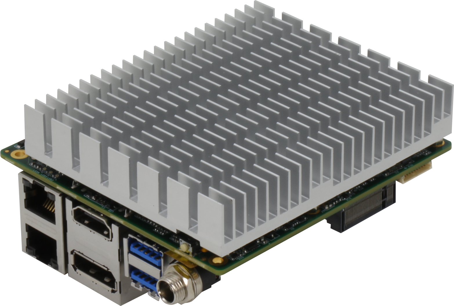
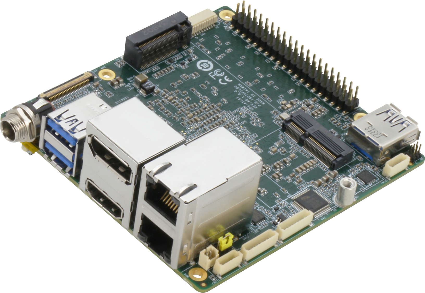
AAEON Technology Inc., renowned for its extensive range of professional developer boards, has introduced the UP Squared 7100. The UP Squared 7100 is powered by Intel® Processor N-series CPUs (formerly Alder Lake-N), enhancing the compact UP Squared range, measuring in at just 85.6mm × 90mm. This release brings significant enhancements in processing performance, speed, and efficiency while retaining the wide industrial utility of its Intel Atom®-based predecessors.
The board will feature Intel® Processor N97 and Intel® Processor N100 as its default CPUs, with additional support for the complete Alder Lake-N processor lineup, including Intel Atom® x7000E Series and Intel® Core™ i3 Processor N-series processors, based on customer requirements. AAEON also notes that the UP Squared 7100 will be compatible with the new Intel Atom® x7000RE Series (formerly Amston Lake) starting from Q1 2025.
Several significant improvements are evident when compared with previous UP Squared boards based on the Intel Atom® platform. The most notable upgrades include the UP Squared 7100’s 16GB of LPDDR5 and 128GB of eMMC, which provide considerable enhancement to the platform’s memory bandwidth and storage capacity. Additionally, the board maintains the 40-pin GPIO that has made AAEON’s UP brand so popular, along with other expansion options such as M.2 E and M-Keys.
Upon examining the I/O features of the UP Squared 7100, it becomes evident that the board is specifically designed for customers seeking to upgrade their industrial applications. This is evidenced by the inclusion of communication protocols such as two COM wafers for RS-232/422/485, onboard TPM 2.0, and a lockable DC jack, all of which enhance the board’s suitability for operation in industrial settings.
Another significant enhancement is evident in the board’s display capabilities, with a move to HDMI 2.0b from its predecessor’s HDMI 1.4b output. The board also features DP 1.2 and eDP 1.3 ports, enabling it to support three simultaneous 4K displays at 60Hz. This improved display capability is complemented by a higher dynamic graphics frequency, courtesy of the integrated Intel® UHD Graphics for 12th Gen Intel® Processors, resulting in more seamless and expedited rendering processes. Additional interfaces comprise three USB Type-A ports supporting USB 3.2 Gen 2 signals, two USB 2.0 ports accessible through a 10-pin wafer, and dual RJ-45 ports for Gigabit Ethernet connectivity.
In terms of operating system compatibility, the UP Squared 7100 offers support for Windows 10 and 11, Ubuntu 22.04, and Yocto 5.1.
For detailed specifications, please visit the UP Squared 7100product page on the AAEON website.
A special digital counter called a BCD counter may count up to ten when a clock signal is supplied.
As previously demonstrated, toggle T-type flip flops may function as separate divide-by-two counters. By joining many toggle flip-flops in a series chain, we may create a digital BCD counter that counts or shows the occurrences of a certain count sequence.
The output of one counting stage serves as the clock pulse for the subsequent stage in asynchronous counters, and clocked T-type flip-flops function as a binary divide-by-two counter. Then, a flip-flop counter has two alternative output states. A divide-by-2N counter may be created by adding more flip-flop stages. However, the fact that 4-bit binary counters only count from 0000 (0) to 1111 (15) is a disadvantage.
We need to have a counter that can count just the binary numbers 0000 to 1001 to create a digital counter that counts from 1 to 10. That is, in decimal, from 0 to 9. Fortunately for us, counting circuits are easily found as integrated circuits; the Asynchronous 74LS90 Decade Counter is one such circuit.
When a clock signal is applied, digital counters count upward from zero to a predefined count value. After the count value is reached, resetting them restarts the counter from zero. A decade counter starts at 0 and counts to 9, then reset to zero after nine counts. It is mandatory to mention that the counter needs at least four flip-flops in its chain to represent each decimal digit to count to a binary value of nine.
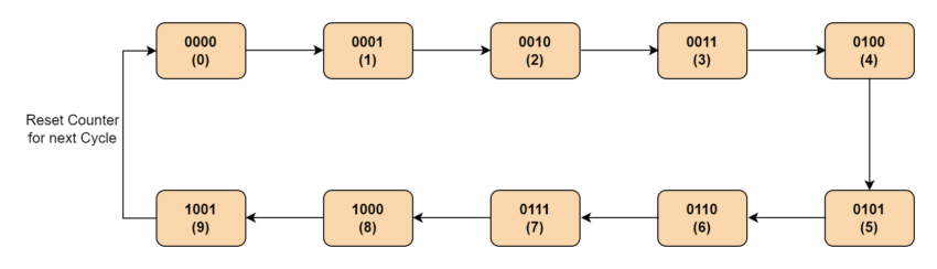
BCD Counter State Diagram
Fig-1: BCD Counter states
Subsequently, a decade counter has four flip-flops and sixteen possible states, out of which only ten are utilized. By connecting many counters, we might count to 100, 1000 or any other desired ultimate count number.
A counter’s modulus is the total number of counts it is capable of counting. A modulo-n counter is a counter that resets to zero after n counts. Examples of modulo-n counters include modulo-8 (MOD-8), modulo-16 (MOD-16), and so on. On the other hand, a “n-bit counter” has a count range of 0 to 2n-1.
However, a counter that resets after ten counts with a divide-by-10 count sequence from binary 0000 (decimal “0”) through to 1001 (decimal “9”) is known as a “binary-coded-decimal counter,” or BCD Counter for short. A MOD-10 counter can be built with a minimum of four toggle flip-flops. This was demonstrated in the Asynchronous Counters tutorial.
It is termed a BCD counter because, in contrast to a straight binary counter, its 10-state sequence is that of a BCD code and lacks a regular pattern. Then, a single-stage BCD counter, like the 74LS90, may count to nine pulses maximum since it counts from decimal 0 to decimal 9. Furthermore, take note of the fact that a digital counter may function as a bidirectional counter, counting both up and down in response to an input control signal.
The 8421 binary-coded decimal code consists of four binary digits. The binary weight of the four utilized digits or bits is indicated by the notation 8421. 23 = 8, 22 = 4, 21 = 2, and 20 = 1, for instance. The primary benefit of BCD coding is its ease of translation between binary and decimal representations of numbers.
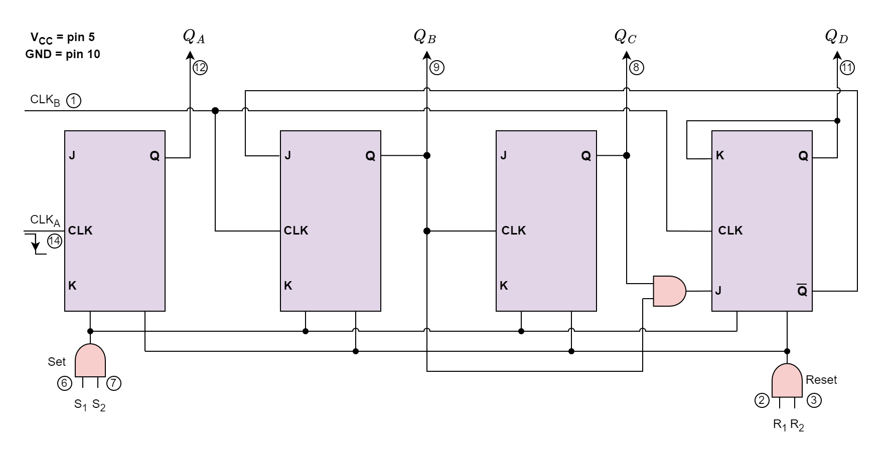
The 74LS90 BCD Counter
In simple terms, the 74LS90 integrated circuit generates a BCD output code by acting as a MOD-10 decade counter. An internal connection between four master-slave JK flip-flops allows the 74LS90 to function as both a MOD-2 (count-to-2) and a MOD-5 (count-to-5) counter. The 74LS90 features three toggle JK flip-flops that create an asynchronous counter driven by the CLK B input, as well as one independent toggle JK flip-flop powered by the CLK A input.
Fig-2: 74LS90 BCD Counter
The letter Q, followed by a numeric subscript that represents the binary weight of the relevant bit in the BCD counter circuits coding, designates the counters’ four outputs. Thus, take QA, QB, QC, and QD as examples. The clock signal’s negative going edge, or when the clock signal CLK changes from logic 1 (HIGH) to logic 0 (LOW), initiates the 74LS90 counting sequence.
Pins S1 and S2 are “set” input pins, while the extra pins R1 and R2 are counter “reset” pins. When the Set inputs S1 and S2 are linked to logic 1, they set the counter to the maximum, or 9 (1001), regardless of the current count number or position. Similarly, the Reset inputs R1 and R2 reset the counter back to zero, 0 (0000).
As previously stated, the 74LS90 counter is comprised of a divide-by-2 counter and a divide-by-5 counter that are both included in the same package. Subsequently, we may utilize either counter to generate a divide-by-2 frequency counter only, a divide-by-5 frequency counter exclusively, or combine the two to generate our preferred divide-by-10 BCD counter.
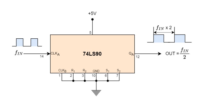
By disabling the four flip-flops that comprise the divide-by-5 counter section, we may generate a conventional divide-by-2 binary counter suitable for frequency division circuits by applying a clock signal to pin 14 (CLKA) and extracting the output from pin 12 (QA).
74LS90 Divide-by-2 Counter
Fig-3: 74LS90 Divide-by-2 Counter
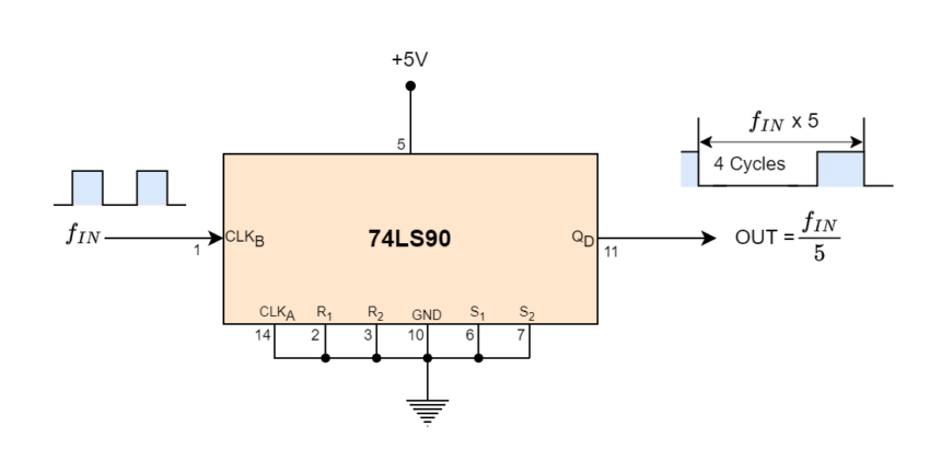
We may deactivate the first flip-flop above and apply the clock input signal straight to pin 1 (CLKB), taking the output signal from pin 11 (QD), as illustrated, to create a typical divide-by-5 counter.
74LS90 Divide-by-5 Counter
Fig-4: 74LS90 Divide-by-5 Counter
It should be noted that the output waveform of this divide-by-5 counter design has a 4:1 mark-space ratio rather than being symmetrical. In other words, a LOW or logic “0” output is produced by four input clock signals, while a HIGH or logic “1” output is produced by the fifth input clock signal.
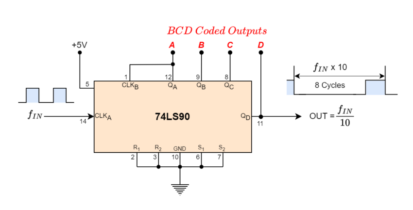
Using both internal counter circuits results in a divide-by-10 BCD decade counter with a 2 times 5 divide-by value. The first output QA from flip-flop “A” may be linked to the CLKB input as illustrated to expand the counter and create a 4-bit BCD counter, as it is not intrinsically coupled to the subsequent stages.
74LS90 Divide-by-10 Counter
Fig-5: 74LS90 Divide-by-10 Counter
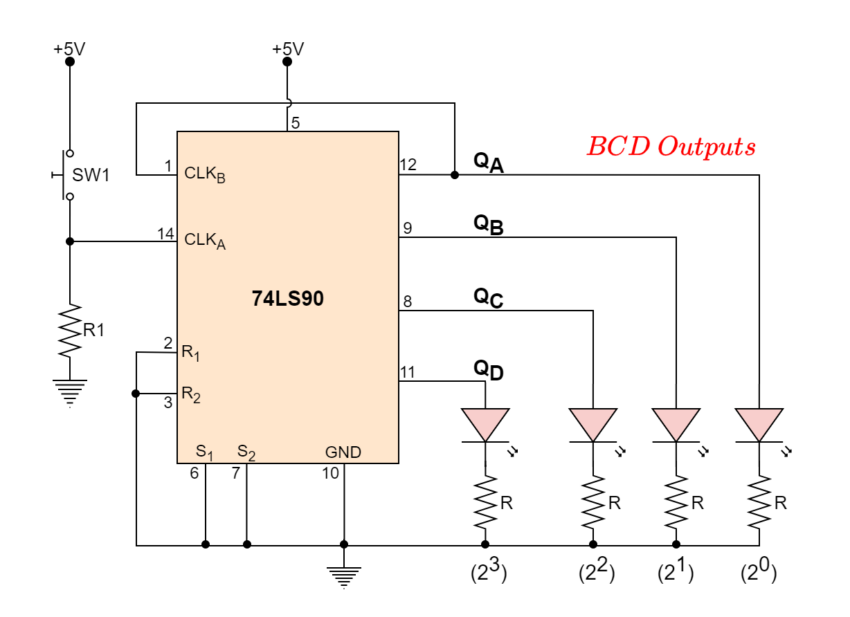
The ability of BCD counters to clear all their flip-flops after the ninth count allows us to see that they are binary counters that count from 0000 to 1001 before resetting. A pushbutton switch (SW1) connected to clock input CLKA will cause the counter to increment by one each time the pushbutton switch is released. We could see the binary-coded decimal count as it happened if we connected light-emitting diodes (LEDs) to the output terminals, QA, QB, QC, and QD as shown.
Fig-6: 74LS90 BCD Decade Counter
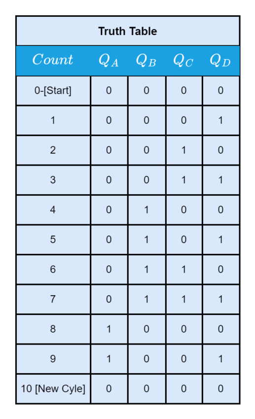
Table-1: Truth Table 74LS90 BCD Decade Counter
When the push-button switch, SW1, is used repeatedly, the count will rise to nine, 1001. The outputs ABCD will reset back to zero to begin a fresh count sequence after the tenth transmission. It is possible to utilize the decade counter to drive a digital display with such a MOD-10 round number of pulses.
The BCD output must first be correctly decoded for us to display the count sequence on a seven-segment display. A Decoder is a digital circuit that can decode the four outputs of our 74LS90 BCD counter and illuminate the necessary display segments.
Driving a Display
A BCD to 7-segment Display Decoder IC, i.e. 74LS47, has previously been developed and manufactured to accomplish that, precisely. The BCD digits A, B, C, and D have four inputs on the 74LS47, and outputs for each segment of the seven-segment display.
One input connection for each LED segment and one that serves as a common terminal or connection for all internal display segments are typically found on a basic 7-segment LED display. Additionally, some displays include a decimal point (DP) option.
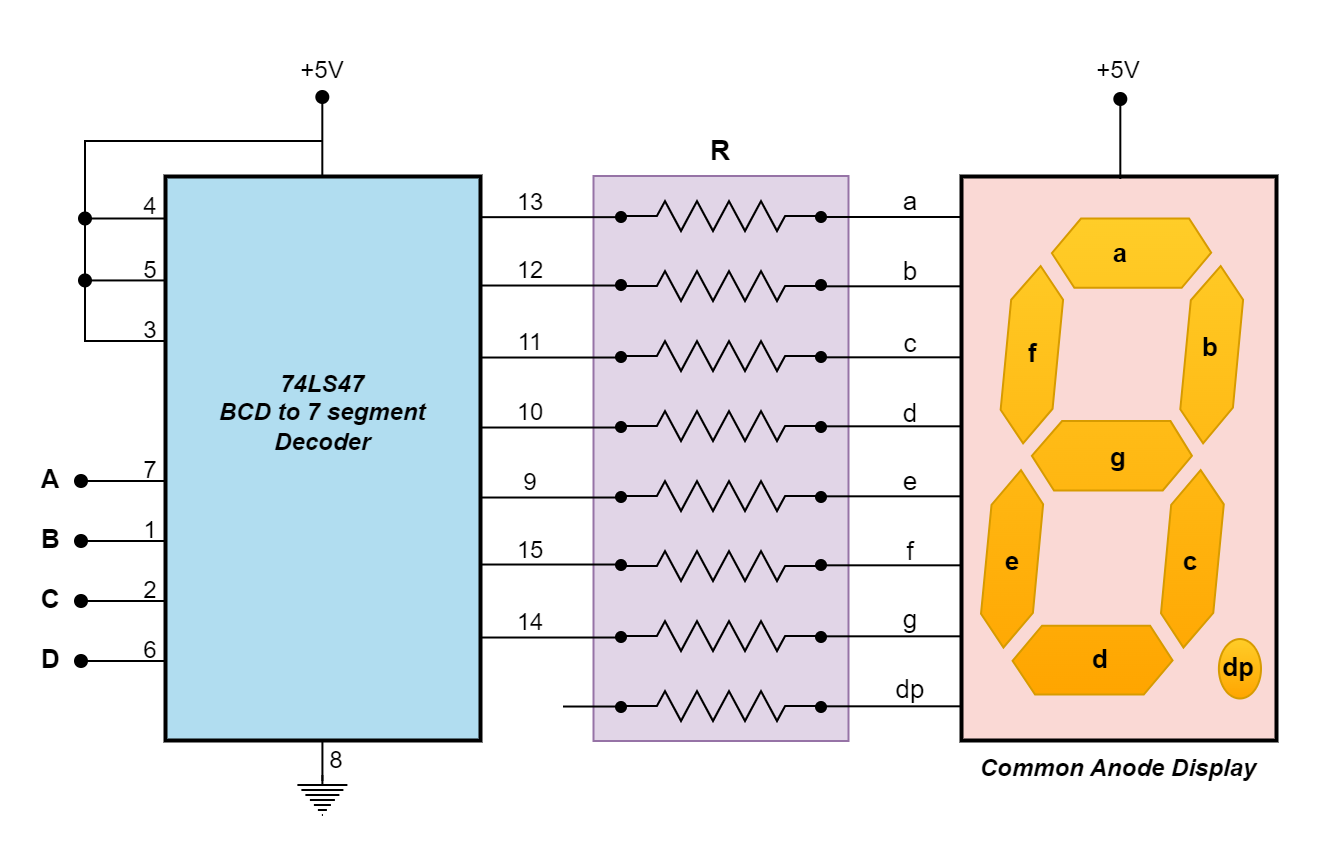
Fig-7: 74LS47 BCD to 7-segment Driver
After receiving the BCD code, the 74LS47 display decoder produces the signals required to turn on the relevant LED segments that show the number of pulses applied. Since the 74LS47 decoder is intended to power a common-anode display, an LED segment can be turned “OFF” with a HIGH (logic-1) output and illuminated with a LOW (logic-0) output. The (Blanking Input/Ripple Blanking Output), (Ripple Blanking Input), and (Lamp test) all need to be open or connected to logic-1 (HIGH) for the system to function normally.
It should be noted that the 74LS48 decoder/driver IC is identical to the 74LS47 in that it has active HIGH outputs intended to decode a common cathode 7-segment display, whereas the 74LS47 has active LOW outputs and is intended to decode a common anode 7-segment LED display. Therefore, a 74LS47 or 74LS48 decoder IC may be required, depending on the kind of 7-segment LED display you have.
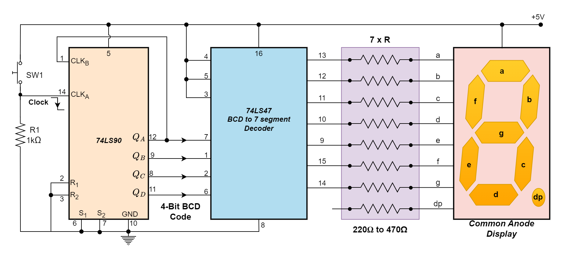
The 74LS90 BCD Counter’s corresponding outputs may be linked to the binary coded decimal inputs of the 74LS47 to enable the 7-segment display to show the count sequence each time the push button SW1 is pressed. The count on activation or release of the push button switch, SW1, may be modified by adjusting the push button’s location and the 1kΩ resistor.
Fig-8: 4-bit BCD Counter Circuit
It should be noted that a 7-segment display is composed of seven separate light-emitting diodes. It is advisable to use a current limiting resistor in series with each of the seven LEDs as illustrated to limit the current flowing through a seven-section display. However, there are two ways we might go about doing this.
Current Limiting Resistors
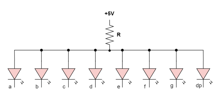
Fig-9: Current Limit by Single Resistor
Single Resistor: As shown in the figure, R is utilized in this instance as a single-series current-limiting resistor. This is the most straightforward way to use the 7-segment display if maintaining a consistent brightness level is not a major priority for you.
An LED’s light output is proportional to the current passing through it; the current passing through the resistor is divided among the display segments. The number of segments that are lit simultaneously now determines the display’s brightness.
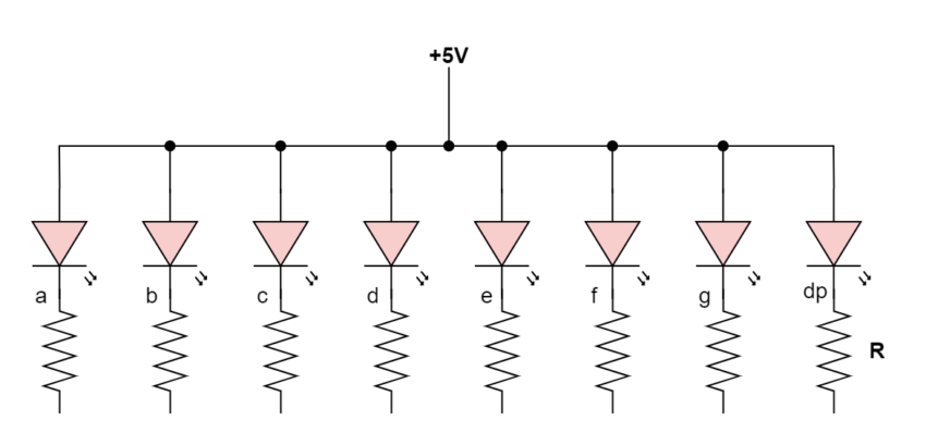
Fig-10: Current Limit by Multiple Resistor
Multiple Resistors: As shown in the above simple BCD counter circuit, each segment has a separate current-limiting resistor in this case.
Since 7-segment displays typically need between 12 and 20 milliamperes to illuminate the segments, the resistance value of the current limiting resistor—all of which will be the same—is selected to keep the current within these ranges. Be aware that if a display is operated at 40mA or more, it may be damaged.
The benefit of this is that the display has a consistent brightness since the brightness of any one LED segment is independent of the condition of the other six LEDs. Since the needed LED intensity is also determined by the quantity of ambient light, the values of the current limiting resistors may be selected to produce the appropriate level of brightness.
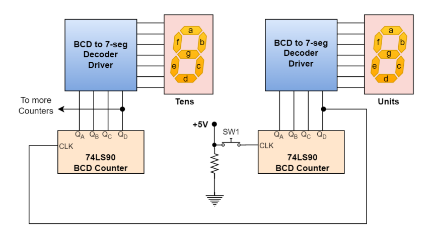
Our design uses a 74LS90 BCD Counter and a 74LS47 7-segment display driver to display basic 0 to 9 digital counters. We would need to cascade two different divide-by-ten counters together to count over 10 and get a 2-digit base-ten counter and display. A two-digit BCD counter would reset to 00 after counting in decimal from 00 to 99 (0000 0000 to 1001 1001). It should be noted that although this code will result in a 2-digit counter, values representing Hexadecimal integers from A to F are invalid.
Similarly, three cascaded decade counters are needed if we wish to count from 0 to 999 (0000 0000 0000 to 1001 1001 1001). As demonstrated, one may create numerous decade counters by simply building one BCD counter circuit for each decade.
2-digit BCD Counter from 00 to 99
Fig-11: 2 digit BCD counter
BCD Counter Summary
A BCD (Binary-Coded Decimal) counter is a type of digital counter that counts from 0 to 9, using a series of toggle T-type flip-flops to create a divide-by-10 sequence. It resets after reaching 9, unlike a standard binary counter that counts from 0 to 15 in a 4-bit configuration.
An integrated circuit that functions as a MOD-10 BCD counter is called the 74LS90. Divide-by-2 and divide-by-5 counters are mixed and can be used separately or in combination to produce the necessary counting sequence. After counting from 0 to 9, it returns to 0. An n-bit binary counter is composed of “n” flip-flops, which count from 0 to (2n-1). Binary counters are counters that operate using a binary sequence.
The 74LS47 is an example of a BCD to a 7-segment decoder that is used to show the BCD output on a seven-segment display. The BCD output is decoded by the 74LS47, which then lights the relevant display segments to reveal the matching decimal digit.
The 74LS90 has multiple pins for clock inputs and for setting and resetting the counter. A working BCD counter circuit that shows the count sequence may be made by connecting the right pins and adding extra parts like resistors and LEDs.
To count beyond nine, several BCD counters can be cascaded. For example, two counters can be used for a two-digit decimal display (00 to 99) or three counters for a three-digit display (000 to 999). The count capacity is increased by one decimal point for each extra counter.
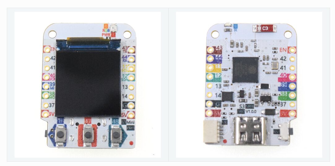
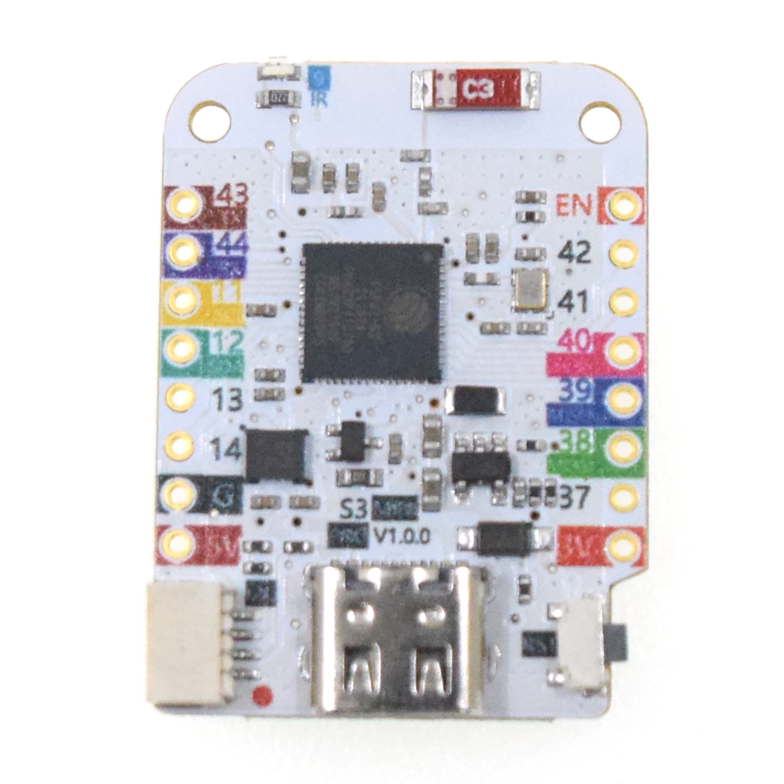
The S3 Mini Pro V1.0.0 by LOLIN is an intriguing addition to the IoT landscape, featuring the powerful ESP32-S3FH4R2 chip. A versatile tool with Wi-Fi, a clear TFT display, and an IMU sensor in a compact form factor, this board is intended to enhance IoT networks’ performance.
S3 Mini Pro V1.0.0: Product Overview and Specifications
The LOLIN ESP32-S3FH4R2 is a flexible chip for many uses. It offers strong Wi-Fi and Bluetooth LE for good wireless connections. It has two processors for great performance and energy saving. With 4MB Flash and 2MB PSRAM. These features facilitate the development of security systems, automated lighting, and air quality monitoring systems.
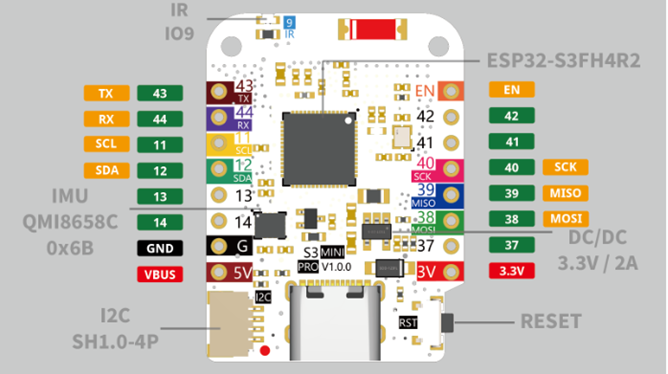
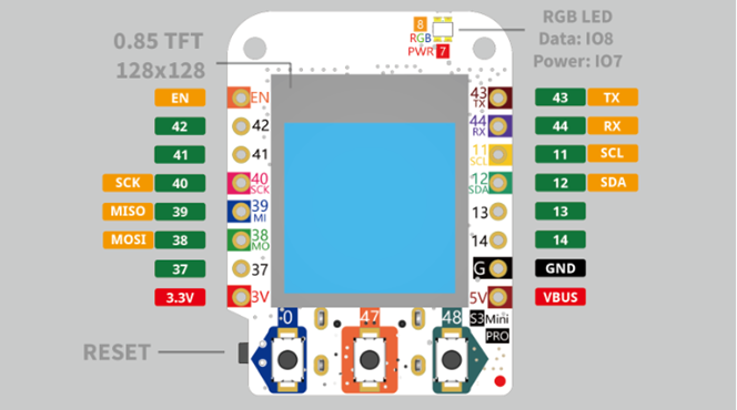
The board comes with a 0.85” 128×128 LCD TFT display, run by the GC9107 or GC9A01. The 6D MEMS IMU (QMI8658C) improves motion tracking, quite useful in fitness devices. This onboard Inertial Measurement Unit (IMU) is essential for wearable devices, enabling precise tracking of physical activities and health metrics. It features the standard 12 IO pins for various uses, three buttons for interaction, and an RGB LED. It also has an IR sensor and supports ADC, DAC, I2C, SPI, UART, and USB OTG interfaces. (Refer to the diagram below )
The LOLIN S3 Mini Pro V1.0.0 supports both MicroPython, Arduino, and ESP-IDF. The board runs on MicroPython by default, but the software support can be switched to either Arduino or ESP-IDF if needed.
S3 Mini Pro V1.0.0 and other boards
The board can be used in predictive maintenance systems to forecast equipment failures and in smart manufacturing setups for critical real-time data processing. The S3 Mini Pro stands out due to its dual-core processors, integrated TFT display, and IMU, which enhance its versatility. Compared to the popular Raspberry Pi Pico, the S3 Mini Pro offers superior wireless capabilities, including Wi-Fi and Bluetooth, along with advanced sensors. This makes it more suitable for complex IoT projects. Although Arduino boards like the Uno are user-friendly, the S3 Mini Pro provides greater computational power and a richer feature set, making it a more robust solution for advanced IoT tasks.
The S3 Mini Pro V1.0.0 by LOLIN is powered by ESP32-S3FH4R2 chip with dual cores, Wi-Fi, Bluetooth, a colorful display, and an IMU sensor. The board is compact yet powerful, suitable for simple or complex IoT projects.
For more details, you can refer Datasheet or visit the Official website or relevant forums. The S3 Mini Pro V1.0.0 is available on AliExpress online.