Using the New ATtiny Processors with Arduino IDE (ATtiny412, ATTiny1614, ATtiny3216, ATtiny1616, ATtiny3217)

While the Arduino series of development boards have ease-of-use features that have made them a darling of the community, there are several situations where using them is not an advisable course of action for a project. Especially in projects where the developers desire a small form factor or the device is required to be low power. As a substitute, developers usually go with Atmeg328p MCU in most situations, but even this increases the size of the project by a significant amount. To solve all of this in recent times, designers turn their attention to a new ATtiny series of microcontrollers and for today’s project, we will focus on how the new series can be used with the Arduino.

A selection of the new ATtiny chips: SOIC ATtiny412, ATTiny1614, and ATtiny3216; QFN ATtiny1616 and ATtiny3217. (image: technoblogy.com)

They may not be as popular as the Atmega328p microcontrollers, but the new ATtiny series of microprocessors from Microchip such as the ATtiny85 or ATtiny2313 needs no introduction. They power a range of tiny devices like the Digispark series of boards but are unfortunately almost useless in tasking applications as they have very limited Flash (usually less than 8K) and RAM (less than 1K). To improve on this, Microchip has released a new series of ATtiny chips with more memory and functionality, enough to go head-to-head with even some of the more expensive and popular Atmega series of chips.

While these chips had amazing features and capacity, they are plagued with two major downsides:

  1. They come in SMD packages and are not breadboard compatible, making them difficult to use for DIY hobbyists
  2. They lack the toolchains possessed by MCUs like the Atmega328p which allows their users to enjoy the same programming ease associated with Arduino boards (and clones).

To go around these downsides, engineers and DIY hobbyists, in no time, started creating different open source solutions that allow the chips to be programmed via the Arduino IDE. For today’s tutorial, we will create an adapter to make the chips breadboard friendly and also examine how someone can use open-source solutions to allow you to program the microcontrollers using the Arduino IDE.

Ready? lets go!

Required Components

The following components are required to build this project:

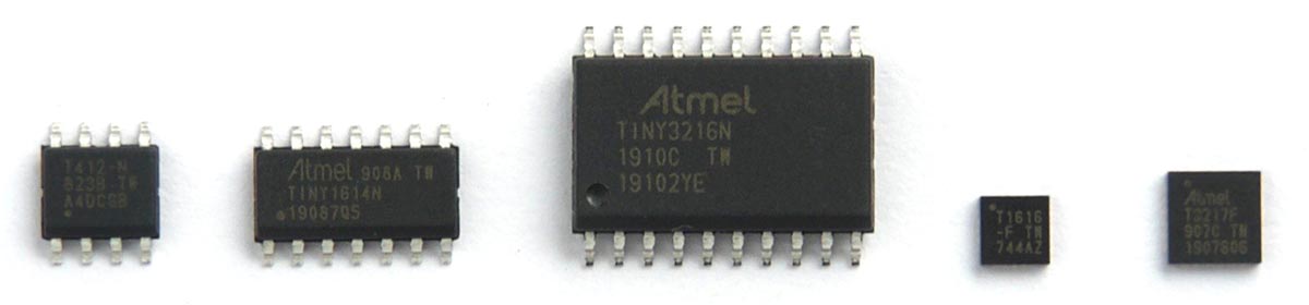
  1. ATtiny 16×4 Microcontroller series. (e.g  ATtiny1614 )
  2. Arduino Nano
  3. 10k Resistor
  4. 10uf capacitor
  5. Jumper wires
  6. Breadboard

These components can be bought from your favorite online stores.

Building the ATtiny Adapter

As mentioned during the introduction, one of the biggest challenges using the new ATtiny series of microcontrollers is their SMD nature which makes prototyping difficult as the chip cannot be plugged directly into a breadboard. To remove this drawback, we will design an adapter for the chip.

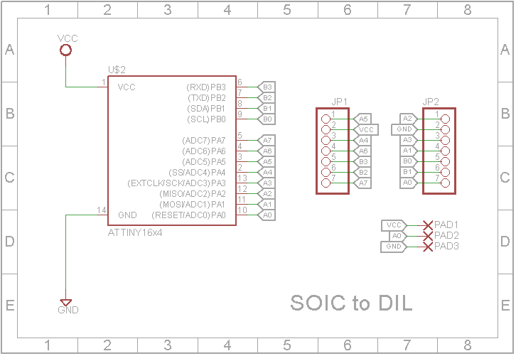
The schematics for the adaptor is a simple one. All we need to do is to route lines from the mounting pads of the ATtiny to header pins. However, this is implemented on a PCB since its the neatest way to implement anything involving SMD components. The adaptor was designed using Eagle CAD and the schematic is shown in the image below;

Adapter Schematics (credit: John Bradnam)

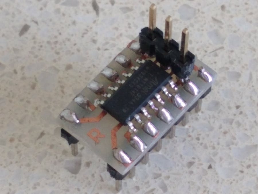
The PCB after the design is shown in the image below:

Adapter board for an ATtiny1614 (credit: John Bradnam)

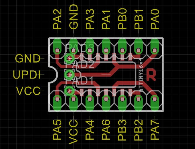
As you’ve probably noticed, the DIL pin layout of the adaptor is different from the layout of the SMD microcontroller itself. This was done to keep the PCB, single-sided, and to also keep its width within 0.3in, as routing the PCB in such a way that the layout is the same as the SMD chip will require a wider or double-sided PCB. The 0.3in width of the adaptor was intentional, as it is the width required for the adapter to fit into a standard 14pin IC socket.

The breakout pins on the top part of the board, represent the UPDI/RESET, VCC and GND pins through which a programmer can be connected to program the microcontroller. Breaking these pins out at the top of the adaptor board makes it easy to program the ATtiny even when the adapter has been soldered into a project.

Adapter board with the ATtiny after soldering (credit: John Bradnam)

To make it easy for you to print your own PCB, all the Eagle CAD source files, including Gerbers, have been attached to the zip file under the download section. Feel free to either print directly or modify it to suit your needs.

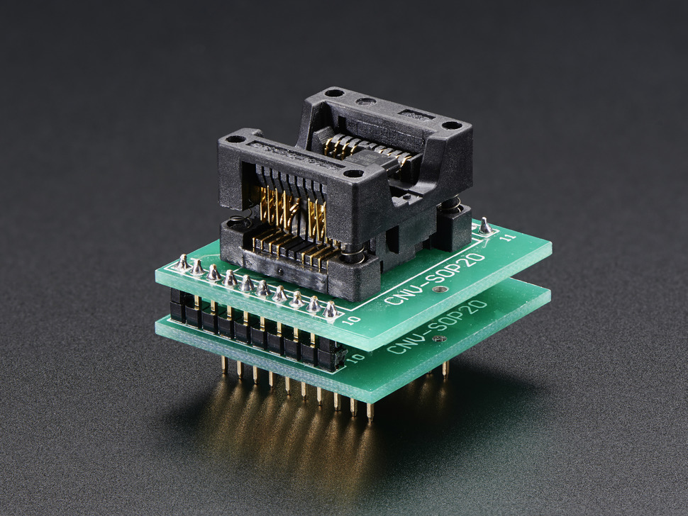
If you will, however, prefer a more flexible adapter that can be reused for multiple chips, without the need to solder and desolder the chips, you can go for this ZiF socket-like adapters on sale at adafruit.

SOIC to DIL on Adafruit

Schematics

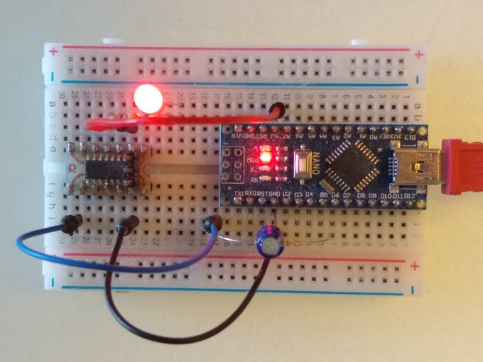
With the adapter in place, the next line of action is to connect it to a programmer which will, in turn, be connected to your computer. For today’s project, we will use an Arduino Nano as the programmer and the schematic below shows how the adapter is connected:

Connect ATtiny to Programmer (credit: John Bradnam)

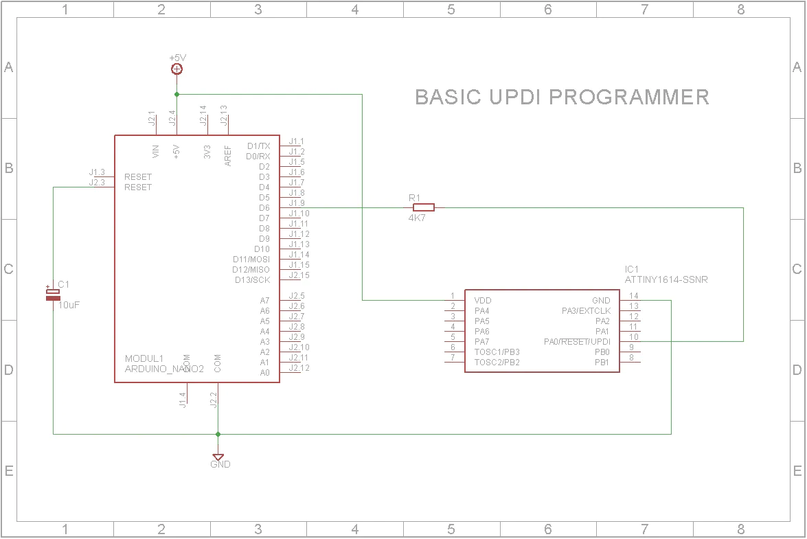
To further highlight the connection, a pin map showing how the components are connected, pin-pin, is provided below:

Arduino  –  Adapter/ATtiny

GND - GND
5V - VCC 
D6 - UPDI

As a demo to show the ATtiny in action, we will implement the Arduino blink example. To do this, connect an LED to the setup as shown below:

Schematics (credit: John Bradnam)

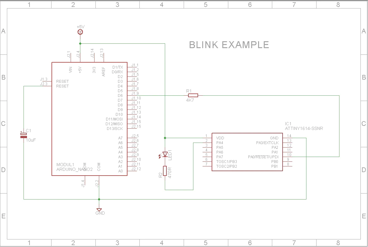
With the programmer and LED connected, we can now proceed to examine the process of uploading code to the ATtiny.

Preparing the Arduino IDE

To bring the ease of programming with the Arduino IDE, which is experienced by the regular Arduino boards and clones, to the new ATtiny MCU series, Spence Conde developed a board package called the megaTinyCore which allows you to effortlessly program the latest series of ATtiny MCUs via the Arduino IDE.

The megaTinyCore requires Arduino IDE version 1.6.3 or later although it was stated on its GitHub page that it may require a much more recent version of the IDE with the initial tests done on version 1.8.9.

The megaTinyCore can be installed on the Arduino IDE in two ways:

  1. Installation via the Arduino Board Manager
  2. Manual Installation

I will explore both methods and let you decide which is easiest or faster.

1. Installation via the Arduino Board Manager

The Arduino board manager was designed to make the installation of new boards and add-ons easy for users. To install the megaTinyCore using this method, follow the steps enumerated below:

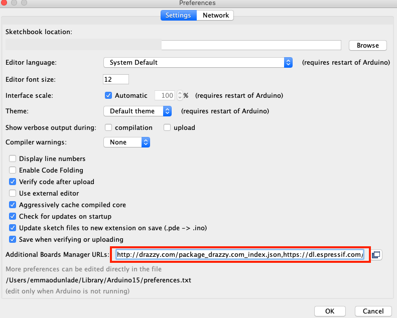
1. Open the preferences window from the Arduino IDE. Go to File > Preferences or Arduino > Preferences if working from a macOS

2. On the preferences window, locate the “Additional Board Manager URLs” text box and enter http://drazzy.com/package_drazzy.com_index.json into the field as shown below and click the OK button

Add the Link to Additional Board URL List

3. Next, open the Arduino board manager. Go to tools>Boards>Boards manager

4. When the board manager opens up, enter megaTinyCore into the search bar and scroll, you will see “megaTinyCore by Spence Konde”, click on install as shown below.

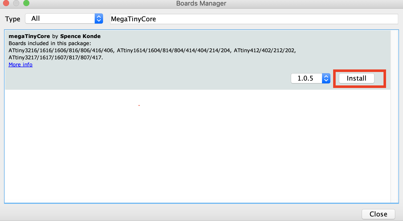
5. Also, search for the “Official Arduino megaAVR boards” package and install the most recent version of that too.

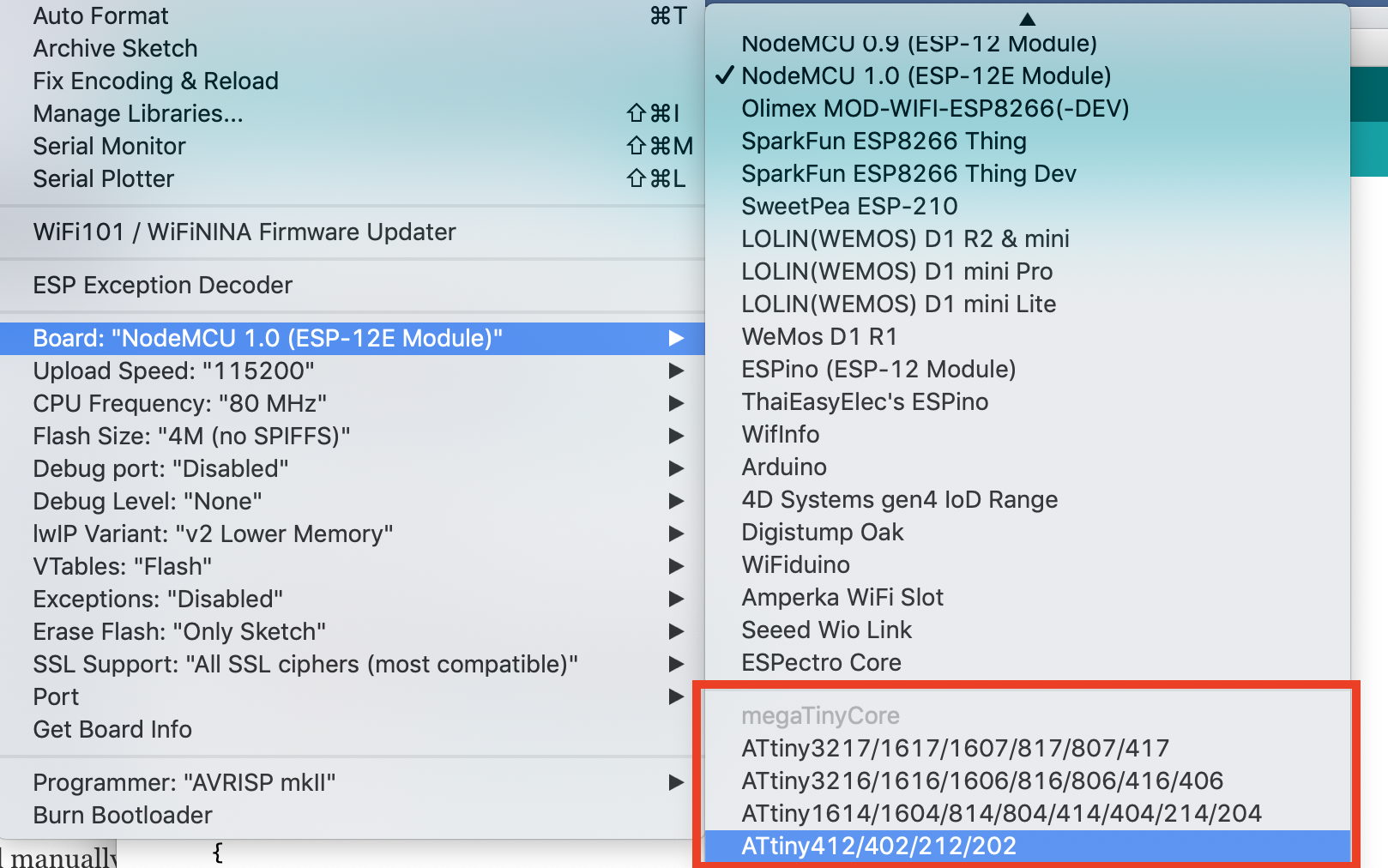
With all of that done successfully, you should now see the Attiny boards all listed under the boards’ section (tools -> Boards) of the Arduino IDE. If that is so, it means the board installation was successful.


2. Manual Installation

The Arduino board manager method provides some level of automation while the manual installation, on the other hand, allows the latest version of the core to be installed, with fixes that may not yet be available in the board manager version of the core. However, to use the manual installation, it is required that you use the board manager to install the latest version of the Official Arduino megaAVR board package for manual installation to work.

Manual installation is recommended if you are interested in contributing to the development of the core, or if having the latest fixes which are not in the released version is important to your build.

To install manually, follow the steps below;

  1. Ensure you have installed the latest version of the Official Arduino megaAVR board package.
  2. Download the MegaTinyCore.zip package (either the “released” version or by downloading the .zip of the master repo) on your computer.
  3. Extract, and place the file in the “hardware” folder inside your sketchbook folder (where your Arduino Sketches are saved). If the hardware folder does not exist, create a new folder and name it “hardware”.
  4. Restart the Arduino IDE

For automatic updates, instead of downloading the zip file, you can download the GitHub client, and sync this repo to the hardware subfolder of your sketchbook folder.

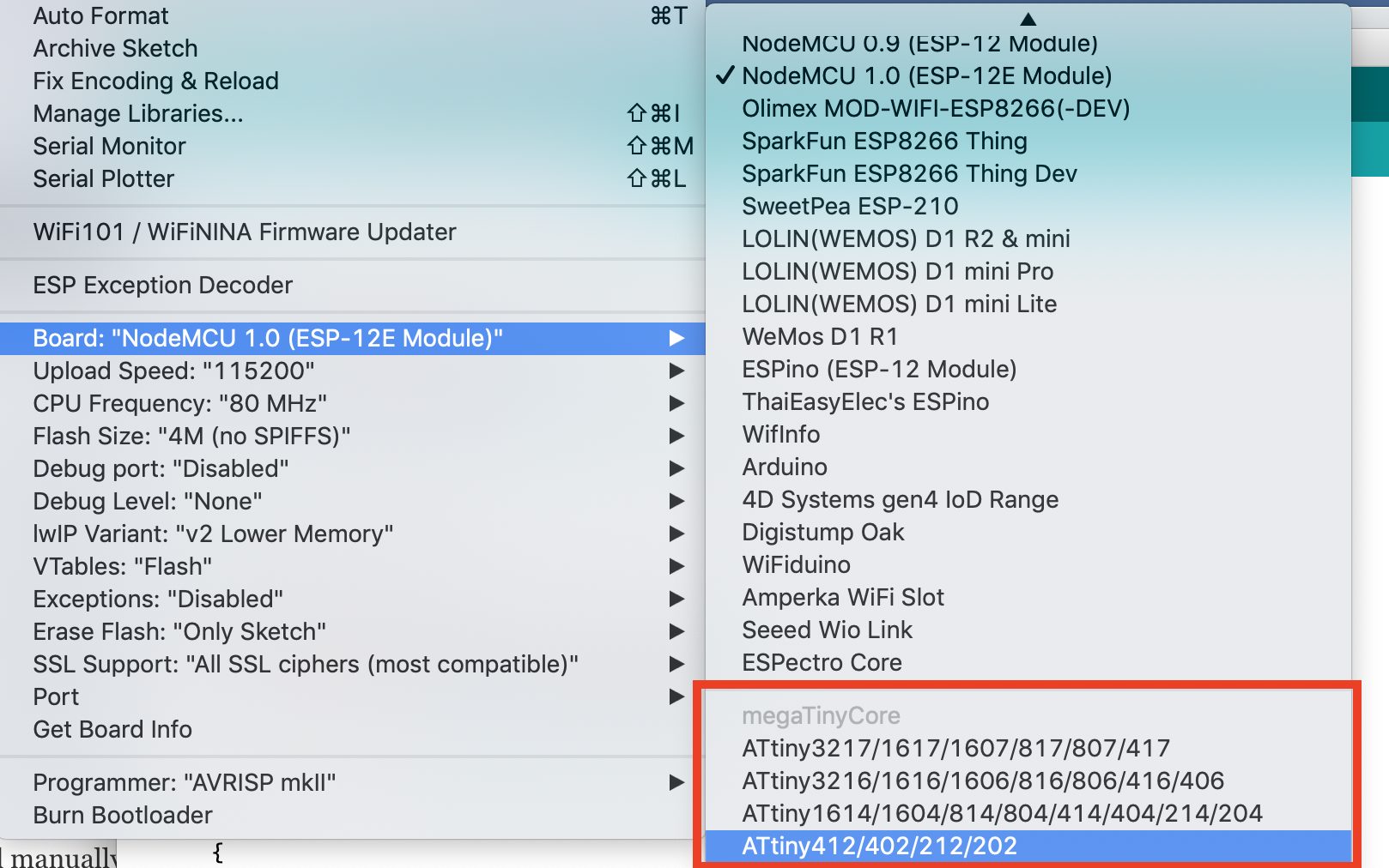
With the installation steps completed, you should now see the Attiny boards all listed under the boards’ section (tools -> Boards) of the Arduino IDE if the installation was successful.

Transforming the Arduino nano to a UPDI Programmer

Another challenge in the use of the ATtiny chip is the way they are programmed. They use a system called the Unified Program and Debug Interface (UPDI for short). This interface uses the RESET pin to program and/or debug the device. Thus, we need to transform the Arduino nano to a UDPI programmer which will send the correct signals to the UPDI/Reset pin.

To do this, we will use the UPDI Arduino sketch created by ElTangas. The sketch converts ATmega328(p)-based Arduino’s, like the Arduino UNO, Nano, and Pro mini, into a UPDI programmer. The sketch, however, does not work on boards based on other microcontrollers, like the 32u4 (on Arduino Micro/Leo) or non-AVR board.

The following steps show how to do this;

  1. Close all instances of the Arduino IDE to avoid errors.
  2. Download and extract the UPDI programmer sketch
  3. Open the jtag2updi folder after extracting the download
  4. Open the sketch jtag2updi.ino and upload it to the Arduino board you will like to use, which for our sake is an Arduino Nano. When you open the code, the .ino file will appear empty and that is fine as all the code is contained in the other files in the same folder as the .ino, but the empty .ino is needed so they can be compiled by the IDE.

With the upload successful, you are now ready to use the UPDI programmer. If you use the new ATtiny series a lot, it will be a smart move to totally dedicate an Arduino pro mini or nano board as a permanent UPDI programmer.

Uploading Code to the ATtiny

To show the project in action, We will upload the Arduino blink example to the ATtiny. The Arduino blink example needs no introduction so I won’t bother to go over the code. 

With the Arduino Nano connected to the ATtiny as described under the schematics section, open the blink example by going to File->Examples->Basics->Blink.

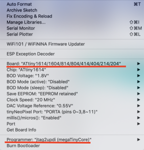
With the example is opened, select the board type and set the programmer (Tools->programmers (scroll towards the end)) as jtag2updi (megaTinyCore).

Add the line of code below, before the setup() function to indicate the pin to which the led is connected (since the chip doesn’t have a built-in LED)

#define LED_BUILTIN 0 //PA4 (Pin 2)

An important thing to note at this point is the pin map below which shows how the Physical IOs should be referenced with Arduino C functions like digitalRead, digitalWrite, analogRead, or analogWrite. For instance, PA4 which is labeled as pin 2 on the chip is referenced as 0 within the Arduino IDE.

Pin Map

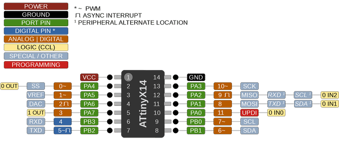
Also note that, unlike the ATmega328 MCU, the new ATtiny processors don’t have separate analog pins. All can be used as either analog or digital, depending on how it is declared within the code.

With the above done, verify the code and hit the upload button. You should in time begin to see the LED blinking. At this point, feel free do disconnect the Arduino nano and power the ATtiny from a 5VDC source.

Demo (credit: John Bradnam)

That’s it!

You can now deploy the new ATtiny series of microcontrollers in your project. Saving space and money. Unlike the former ATtiny microcontrollers, these new series of MCUs come with a higher amount of flash memories, cost a whole lot less, and are all-around more efficient. I advise they should be considered as the MCU of choice for your next tiny, low-cost, low-power project.

STINGER96 – 96Boards IoT Edition Baseboard

Shiratech launches its NEW 96Boards IoT solution based on ST STM32MP157 MCU + QUECTEL BG9IoT6 NB-IOT modem.

The Board is 96Boards IoT Edition Extended Compatible (IE extended). Full support for 96Boards IoT Edition (IE) Low Speed expansion connector.

STM32MP157 Main features

CORE

  • 32-bit dual-core Arm® Cortex®-A7
  • Up to 650 MHz (Up to 4158 CoreMark®)
  • L1 32 Kbyte I / 32 Kbyte D for each core
  • 256 Kbyte unified level 2 cache
  • Arm® NEON™ and Arm® TrustZone®
  • 32-bit Arm® Cortex®-M4 with FPU/MPU
  • Up to 200 MHz (Up to 673 CoreMark®)

MEMORY

  • External DDR memory – DDR3 – 256M X 32Bit
  • 708 Kbyte of internal SRAM: 256 KB of AXI SYSRAM + 384 KB of AHB SRAM + 64 KB of AHB SRAM in backup domain and 4 KB of SRAM in backup domain
  • NAND Flash – SLC NAND Flash Parallel 1.8V 8Gbit 1G x 8Bit 63-Pin VFBGA

SECURITY

  • Secure boot, TrustZone® IPs, active tamper

CONNECTIVITY

  • On Board Camera DSMI 12Bit interface
  • JTAG interface – ST LINK JTAG Interface
  • 1 x 10/100/1000 Ethernet based on KSZ9031RNX Microchip Phy
  • 2 x USB2 interfaces (One for External Connector, One for BG96 Modem)
  • 1 x Uart (Via FTDI & Micro USB interface)
  • 1 x SD interface
  • Full 96 IOT LS connector Interface (1.8V interface)
  • 2 x UART
  • 2 x I2C
  • GPIO Support A-L
  • 1 x SPI
  • 1 x PCM

BG96 (NBIOT Modem) – Interface

  • 2 x Control lines
  • 1 x USB Interface

BG96 Main features
CORE

  • Quectel BG96 LTE CAT-M1 Modem
  • Modem speed 300Kbps DL / 375Kbps UL
  • Built in GPS
  • Industrial grade
  • Low Power
  • Compatible with 96Boards CE and EE boards
  • I2C, UART, GPIO for modem operation

POWER

  • Input power 5V

MECHANICAL

  • 96Boards IOT Edition Form Factor –
  • Standard SMARC form factor: 85mmx 54mm
more information: www.shiratech-solutions.com

Kryptor FGPA is a Hardware Security Module that adds Complex Open-source Encryption

Designed for processors that support serial interfaces, the one-chip module offers all the functionalities of a dedicated HSM within a single compact MAX10 FPGA chip.

The new release from Skudo is a professional FGPA development board built as an encryption solution to project boards like Raspberry Pi, Arduino, and BeagleBone. It is a plug and play Hardware Security Module that provides a compact pre-configured FPGA chip with functionalities for encrypting data, and can easily be used by any maker board.

“Any controller board (e.g. Raspberry Pi, Arduino etc.) can be connected to the Kryptor PCB via SPI, 12C and UART using a simple data protocol (free Linux API software libraries are also provided) enabling access to the functionalities of the Hardware Security Module (symmetric encryption, asymmetric encryption, hashing, keys generation/storing/management and a True Random Number Generator). Any maker is able to access those functionalities and build complex solutions based on them”.

Being able to offload an encryption work via 12C, SPI, or UART to your application helps you to focus more on the application’s code and worry less about implementing encryption.

“To make the Kryptor easy to use for IoT developers and makers, we also provide a free and easy-to-use API for Linux (e.g compatible with Raspberry Pi), which lets almost anyone start working with Kryptor in mere minutes,” Skudo adds.

Features of the HSM include:

  • FPGA: Intel/Altera MAX10 8K LE (10M08DAF256C8G)
  • Dimensions: 23×35 mm
  • Internal flash: 1376 Kb
  • Internal RAM: 378 Kb total
  • GPIO: 250 available from the FPGA (fewer accessible via board)
  • Operating frequency: 100 MHz
  • Control: API / encrypted command line interface (CLI)
  • Platform compatibility: Linux, RPi, Arduino, etc.
  • Duplication protection: Anti-piracy duplication protection via chip ID
  • Encryption speed: symmetric encryption speed up to 108 Mbps on a single core (SPI link speed capped at 2 Mbps)
  • Power consumption: ~58 mAh (idle state) to ~65 mAh (constant operations)

One advantage it has over most commercial elliptic curve cryptography chips is that its entire implementation can be verified, as both hardware and software designs are available for inspection.

“The security of any encryption solution cannot rely on blind trust for a certain chip manufacturer. Rather, trust must be earned – which is why we’re making our files available for review by completely independent third-party companies for review and analysis.”

Another beautiful thing about the module is that it replaces all SW based encryption functionalities with HW based ones, so there is no need to consider using any Operation System which in turn reduces the chances of potential surface attacks.

More details on the Kryptor’s FGPA board as well as progress updates can be found on Skudo’s product release page or it’s Crowd Supply page where it has been pre-launched.

Elektor Article: DCF77 Emulator with ESP8266

Replace over-air time by Internet time

About twenty years ago I recycled and modernised a vintage clock with Nixie tubes built by my father in the nineteen seventies. I replaced the digital logic by a microcontroller and used a DCF77 receiver module instead of the original 50-Hz derived timebase. Over many years the clock has worked fine, but recently DCF77 reception in my house has worsened due to electromagnetic interference created by modern switching power supplies, I suppose. So I decided to replace the DCF77 receiver by some form of Network Time Protocol (NTP) client.

Elektor Article: DCF77 Emulator with ESP8266 – [Link]

What Is Turnkey PCB Assembly?

PCB Assembly is a process that requires knowledge not just of PCB components and assembly but also of printed circuit board design, PCB fabrication and a strong understanding of the final product. Circuit board assembly is just one piece of the puzzle to delivering the perfect product the first time – without rework or assembly errors.

PCBGOGO’s printed circuit board assembly service is a leading turnkey solution for PCB fabrication and assembly under one roof specializing in small and medium volume PCB fabrication with fast lead-time and low minimum from 1pcs for PCBA.

What is Turnkey PCB Assembly?

‘Turnkey’ refers to a product or service that is ready for immediate use for the buyer and when applied to PCB assembly, this means that the supplier will handle all aspects of the PCB project. This includes the procurement of parts, components and the manufacturing of PCB. Turnkey PCB assembly uses an internet cloud-based software and PCB manufacturers to develop printed circuit boards quickly, efficiently and cost-effectively for small businesses. Essentially, a full turnkey solution allows you to have greater freedom to focus on designing PCBs whilst the supplier can handle the rest of the operations. Turnkey solutions offer an efficient and cost-effective way to assemble and test circuit boards for products. This also offers companies a way to receive printed circuit boards with the shortest lead times possible. Full turnkey PCB assembly includes services necessary to create your finished products, beyond PCBA. These include:

PCB prototypes

  • High volume PCBA
  • Box build
  • Inventory management
  • Shipment to your end-user.

How to get a quote for turnkey PCB assembly services?

  1. PCBs Online Quote: You can get a PCB price instantly after a few option selections. All PCBs will be electrically tested. Click PCB quote online to get a quote now.
  2. PCB Assembly online Quote: This is also an instant quote for the cost of labor for PCB assembly in seconds. Click PCB assembly quote to get a quote now.
  3. BOM Pricing: Send your BOM (Bill of Materials) to service@pcbgogo.com, we will email you the BOM price in 24 hours. BOM must include the quantities, reference designators, and manufacturer name and manufacturer part number.
  4. If you already have your quote, then you are ready to place your order at your convenience!

PCBGOGO quick-turn turnkey PCB assembly services

PCBGOGO is a specialist electronic manufacturing provider with extensive experience in PCB manufacturing and PCB assembly solutions for small to medium businesses. Min. quantity can be 5pcs. For over 10 years we have been proudly servicing customers all over the world with high-quality boards and reliable, industry-leading electronic manufacturing services right here from Shenzhen, China.

PCBGOGO has a workforce of approximately 400 people. We are proud of our reputation as a leading specialist in surface-mount, thru-hole, and mixed technology PCB assembly and electronic manufacturing services as well as turn-key electronic PCB assembly. Our customers let us be the full turn-key provider for their project from manufacturing to assembly and testing. Through our strong network of well-proven circuit assembly and manufacturing partners, we can provide the most advanced and nearly limitless capabilities for your prototype or production PCB application.

Save yourself the trouble that comes with the procurement process and dealing with multiple components vendors. Our experts will find you the best parts for your final product.

We offer the following PCB assembly services:

  • Quick-turn prototype assembly
  • Turn-key assembly
  • Partial turn-key assembly
  • Consignment assembly
  • RoHS compliant lead-free assembly
  • Non-RoHS assembly
  • Conformal coating
  • Final box-build and packaging

PCBgogo – custom prototype and mass value fabrication,high-quality pcb assembly

What is a Rugged Mini PC?

Rugged mini PCs have exploded in popularity in recent years due to their affordability, small form factor, and simplicity. Included among them are powerhouse workstations like the forthcoming Trenton Systems ION Mini PC.

These small rugged computers are ideal for military, industrial and commercial applications where conditions are extreme, weight is a concern and/or space is limited, such as on a submarine, on board a plane or in a crowded desert outpost.

Most importantly, you’re probably wondering how they can benefit your program or application. Well, here’s the quick and dirty: Rugged mini PCs are affordable, stress-tested and compact.

And that’s just what some applications need in a rugged computer.

What is a Rugged Mini PC? – [Link]

Let Ugreen all-in-one 4-Port 65W GaN fast charger solve all your worries

Highlights:

  • Essential for Travel/Office/Home
  • One charger solves all the troubles.
  • No need to bring multiple charging adapters when travelling;
  • No worries about the large size of the traditional multi-port charger, which is not convenient for carrying.
  • Work easily, no longer need to equip each device with a different charger, make the desktop clean and tidy, and no longer worry about the cluttered power cord and the insufficient socket.
  • Designed for your ideal life, spend a good time with your family, no longer dispute about who will charge first.

The Lightest & Smallest 4-Port (GaN) Charger 65W

Equipped with 4 ports, the 65W GaN PD Charger has an ergonomic design and saves up to 50% space for you.

Only 165g, half the weight of a roll of toilet paper.

Combination of 3 USB-C & 1 USB Port

With the popularity, high frequency use and more and more devices supported the Type-C, adhering of the design concept of All in One, we put 3 USB-C(Type-C)  and USB-A ports in this little cube charger.

Charge Smart with Efficient

Say goodbye to various chargers;

Charge 50% within 30 min for iPhone X, the Ugreen 65W GaN PD Charger features fast charge for iPhone, iPad Pro 2020, Nintendo Switch Lite and AirPods at the same time.

Intelligent power management delivers optimal charging power to fast charge your devices.

Designed for Apple Fans

Only one charger to meet all i-devices for Apple Fans;

The 65W charger can charge MacBook Air 2020, iPad Pro, iPhone 11 Pro, AirPods Pro and iWatch etc.

The Ugreen charger is able to charge almost every kinds of digital devices, and it supports nearly all Fast Charging Protocols, making sure your devices are charged with 3-times better efficiently. One charger for your work and casual life.

Revolutionary GaN Tech

To achieve all above, we applied the latest GaN semiconductor material to the charger, which allows power components to work under higher voltage and more frequent switches, hence to boost up the charging efficiency with even smaller design.

More Functions in a smaller products

The GaN technology makes it possible to fast-charge 4 devices, meeting multiple needs of all family members.

Only half the size of porker. The best choice to replace the bulky laptop wall charger;

Ideal for creators, designers, students or all consumers who use multiple electronic devices

A Great Fit for Worldwide

The foldable charger fits all Britain, US and EU standards, making it available in every corner of the world. It also supports voltage from 110V to 240V even in its foldable design. For specialists around the world, Ugreen GaN Fast Charger can meet all your needs.

Videos

EVAL-ADSMOKEKITZ Smoke Evaluation Kit

Analog Devices’ EVAL-ADSMOKEKITZ smoke evaluation kit enables designers to get smoke detection solutions quickly

ADI’s EVAL-ADSMOKEKITZ is an out of the box smoke evaluation kit for high accuracy, integrated, smoke detection monitoring. It provides users with all the necessary components to get up and running quickly with designing their custom smoke detection products, including the WaveTool graphical user interface (GUI). This GUI enables designers to drive smoke detection solutions to market quickly and unlock complex technology to those who are less experienced smoke designers.

Kit Includes

  • EVAL-ADPD188BIZ-S2: A complete integrated optical module with matching smoke chamber to support industry global regulations including UL217 ed 8. and UL 268 Ed. 7. It features a reduced footprint, lower power consumption, and increased safety.
  • EVAL-CHAMBER: ADI designed matched smoke chamber comes with a reference design so users can create a more positive smoke detection device with greater verification results, straight out of the box. This enables designers that do not have technical expertise in the area of smoke design or the time to create and test their custom smoke chamber.
  • EVAL-ADPDUCZ: Microcontroller board used to support the ADI EVAL-ADPD188BIZ-S2.

Features

  • Supports UL-217 edition 8/ UL-568 ed. 7, EN-54 GB and ISO standards
  • Increased safety; reduced nuisance alarms using a dual-wavelength detection
  • Greater power performance/efficiency – 3x lower power dissipation, enabling smaller low-cost batteries
  • Integrated optical module: optimized form factor (3.8 mm x 5 mm x 0.9 mm with 1 blue LED, 1 IR LED, and 2 photodiodes)
  • Greater industrial design options, 75% fewer discrete components
  • Reduces calibration challenges – loop calibration at the final test
  • EVAL-CHAMBER smoke chamber
    • Optimized to work with ADPD188BI
    • Passes UL217 nuisance test
    • Enables easy-to-implement self-diagnostics

more information: gr.mouser.com

STLINK-V3MODS Embedded Debugger and Programmer

STMicroelectronics’ small size debugging and programming probe is designed for STM32 microcontrollers

STMicroelectronics’ STLINK-V3MODS is a small size debugging and programming probe for STM32 microcontrollers. The JTAG/SWD interfaces are used to communicate with any STM32 microcontroller located on an application board.

The STLINK-V3MODS also provides a Virtual COM port interface enabling the host PC to communicate with the target microcontroller through one UART, and bridge interfaces (SPI, I²C, CAN, GPIOs) simplifying, for instance, the field programming through the bootloader. The STLINK-V3MODS is ready to be embedded in any application and can be directly soldered on the PCB motherboard.

Features

  • Modular probe with small size: approximately 15 mm x 30 mm
  • Direct-to-PCB implementation by 2 x 16-pin 1.27 mm edge castellated vias, with all signals available in required minimum PCB surface
  • Self-powered through a USB connector (MicroB)
  • USB 2.0 high-speed compatible interface
  • Direct firmware update (DFU) support
  • JTAG / serial wire debugging (SWD) specific features:
    • 3 V to 3.6 V application voltage support and 5 V tolerant inputs
    • JTAG communication support
    • SWD and serial wire viewer (SWV) communication support
  • Virtual COM port (VCP) specific features:
    • 3 V to 3.6 V application voltage support on the UART interface and 5 V tolerant inputs
    • VCP frequency up to 15 MHz
  • Multi-path bridge USB to SPI/UART/I²C/CAN/GPIOs specific features:
    • 3 V to 3.6 V application voltage support and 5 V tolerant inputs
  • Drag-and-drop Flash programming
  • Two-color LEDs: communication, power

more information: www.st.com

TOP PCB Companies