Altium Takes PCB Design and Realization to the Next Dimension

Altium 365 platform empowers designers to work from anywhere, and connect with anyone.

Altium, LLC, a leader in PCB design software, today announced the availability of Altium 365, the world’s first cloud platform for PCB design and realization. The platform is poised to transform the electronics industry by bridging the gap between PCB designers, part suppliers, and manufacturers through seamless collaboration as the design evolves.

Altium 365 works harmoniously with Altium Designer, the industry standard for PCB design, to deliver the most connected experience for PCB design and manufacturing. This allows design teams to drastically reduce miscommunication, re-design iterations, and time to market.

“A long-term change in the way that the various stakeholders in the electronics industry work together is taking place,” said Ted Pawela, Chief Operating Officer at Altium. “Whether working from home, office or traveling for business, the need to work from anywhere in the world without being tethered to your desktop is here to stay. Altium is paving the way for engineers and designers to work from anywhere, and connect with anyone by making the Altium Designer user experience more collaborative and more readily available than ever before.”

With Altium 365, users can bring together the stakeholders and participants of their choosing (even those who do not have Altium Designer), while keeping their IPs secure and design under control. This cloud-based platform provides a completely new way to share, visualize, and mark-up PCB designs for all stakeholders involved, from design managers to manufacturers, while allowing other designers to connect to the same PCB design with Altium Designer to author changes.

Teams can organize designs, libraries, and participants in one place, and share links to their designs for easy, real-time collaboration. Designs are always accessible at any time, on any device, anywhere. By leveraging CAD-specific intelligence, design data can be stored in a way that makes projects, files and version history accessible and easy to navigate on the web.

“We use the Altium 365 workspaces as a way to keep all our components, designs and projects all in one place, so that everyone is working from the same source of information. We are able to design faster with teams at different locations.” – Chris Brawn | Senior Design Engineer | Skyships

Altium 365 provides a built-in co-designer capability between electronic and mechanical domains through native integration with PTC Creo®, Dassault Systèmes® SolidWorks™ and Autodesk Inventor®. PCB designers and mechanical CAD designers are now able to collaborate more efficiently and creatively than ever before.

Altium 365 also helps streamline the manufacturing process. Designs can be packaged and shared with internal and external shareholders with just a simple web link that can be accessed via any platform on any internet-enabled device.

“We are using Altium 365 in our manufacturing process. We can immediately share the Bill of Materials and version updates, so our manufacturers can know if something changed and why right away.” – Dario Pennisi | Hardware Development Manager | Arduino

By adding the flexibility of sharing and collaboration of the cloud to the power of desktop PCB design software, Altium is making a big leap towards unifying the electronics industry.

To learn more about Altium 365 + Altium Designer 20, visit https://www.altium.com/altium-designer/whats-new

Axiomtek’s Quad-View 3.5” Embedded Board with AMD Ryzen™ Embedded V1807B/V1605B Processor – CAPA13R

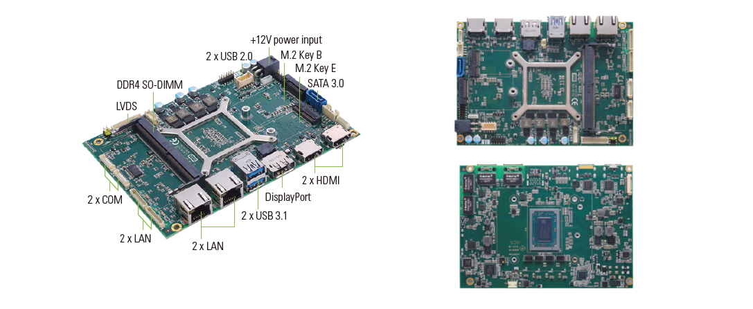
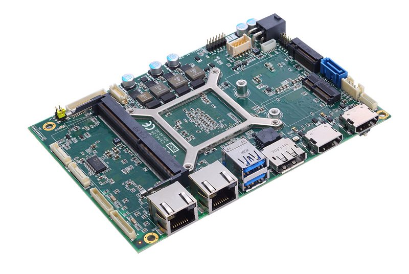
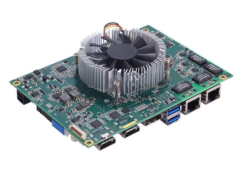
Axiomtek – a world-renowned leader relentlessly devoted in the research, development and manufacture of series of innovative and reliable industrial computer products of high efficiency – is pleased to introduce the CAPA13R, a high-performance 3.5” embedded board with quad displays. The CAPA13R is powered by the onboard AMD RYZEN™ Embedded V1807B/V1605B processor with AMD Radeon™ RX Vega graphics. The embedded board is well-suited for graphics-intensive applications such as medical imaging, video surveillance, 3D simulators, optical quality control, digital signage, kiosks/POI, thin clients, and more.

The integrated AMD Radeon™ RX Vega graphics with support of DirectX 12 and OpenGL 4.5 marks the cutting edge of embedded graphics. The CAPA13R offers quad display capability through two HDMI, one DisplayPort and one LVDS interfaces. Its onboard CPU is attached on the rear side of the board, which can aid with heat dissipation and offers flexibility for easy system integration and minimum maintenance. Moreover, the CAPA13R offers multiple expansion interfaces with one M.2 Key E slot for wireless modules and one M.2 key B slot for storage cards. One 260-pin SO-DIMM socket on the CAPA13R supports up to 16GB of DDR4-2400 (V1605B) and DDR4-3200 (V1807B) memory. The system has a +12V DC power input.

“The new AMD RYZEN™ Embedded V1000 series is the best choice for embedded solutions that require a high-resolution display and full-graphics feature, and offers the benefits of a smaller footprint,” said Michelle Mi, Product Manager of Embedded Board and Technology Business Unit at Axiomtek. “The CAPA13R has four GbE LAN ports to connect with industrial cameras for machine vision applications and four independent displays for graphics-oriented appreciations, like digital signage, gaming, infotainment, etc. Its scalability, optimized graphics and low profile design offers a high level of versatility to help system integrators drive their projects forward.”

To satisfy increasing demands of connecting more peripheral devices, the CAPA13R provides two USB 3.1 Gen2, two USB 2.0, four GbE LAN, one RS-232, one RS-232/422/485, two HDMI, one DisplayPort, one LVDS, one SATA-600, 8-channel DIO, one HD audio, and an SMBus compatible with I2C. Furthermore, it supports hardware monitoring features to monitor temperature, voltage, fan speed and more. The built-in watchdog timer keeps the system running smoothly. Additionally, the CAPA13R supports Windows® 10.

Advanced Features:

  • AMD® RYZEN™ Embedded V1807B and V1605B processors
  • One DDR4 SO-DIMM for up to 16GB of memory
  • Four GbE LAN
  • Two HDMI, one DisplayPort and one LVDS
  • M.2 Key E (PCIe x1, USB 2.0)
  • M.2 Key B (SATA default, PCIe x2 for option, USB 2.0)

Axiomtek’s new CAPA13R is now available for purchase. For more product information or pricing, please visit our global website at www.axiomtek.com or contact one of our sales representatives at info@axiomtek.com.tw.

3V To 5V Boost DC-DC Converter using MAX711

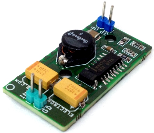
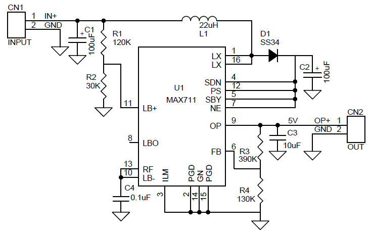
The circuit shown here is a compact and high-efficiency boost converter that has been designed for hand-held equipment. This boost converter converts 2 cells (3V) DC power into 5V DC with output load current up to 500mA. Typical efficiency when boosting battery inputs is 85%. The circuit is based on MAX711 which integrates a step-up DC-DC converter with a linear regulator to provide step-up voltage conversion. The circuit is optimized for battery applications where the input varies above and below the regulated output voltage. The project has an input range from +1.8V to +11V. The circuit is set for 5V output but it has an adjustable output that can be set from +2.7V to +5.5V with the help of two R3, R4 resistors. The IC contains a comparator for low battery detection. If the voltage at LBI+ falls below that at LBI- (typically connected to REF), LBO goes low. Hysteresis is typically 50mV. You can set the low-battery monitor’s threshold with two resistors, R1 and R2.

The MAX711 integrate a step-up DC-DC converter with a linear regulator to provide step-up/down voltage conversion. The step-up switch-mode regulator contains an N-channel power MOSFET switch. It also shares a precision voltage reference with a linear regulator that contains a P-channel MOSFET pass element. Step-Up Operation A pulse-frequency-modulation (PFM) control scheme with a constant 1μs off-time and variable on-time controls the N-channel MOSFET switch. The N-channel switch turns off when the part reaches the peak current limit or the 4μs maximum on-time. The ripple frequency is a function of load current and input voltage.

Features

  • Supply Input Two AA Cell- 3V DC (+1.8V to +11V Range)
  • Output 5V DC (Adjustable 2.5V to 5.5V)
  • Output Load 500mA Maximum
  • Efficiency for battery input is 85%

Schematic

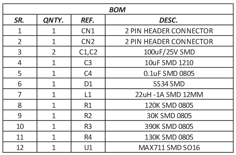
Parts List

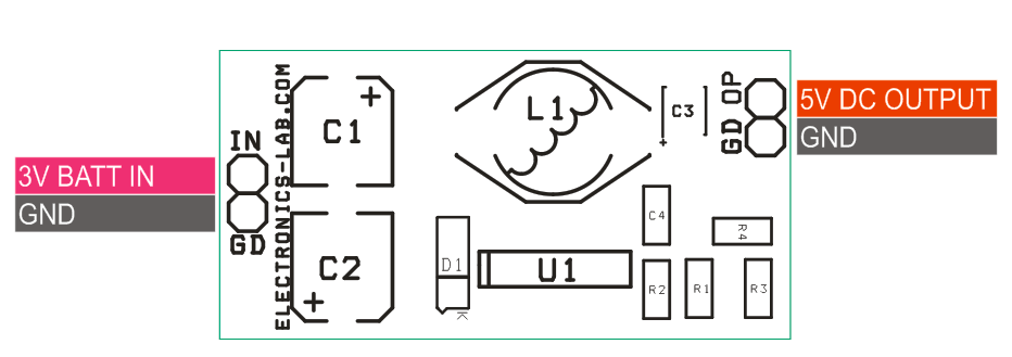
Connections

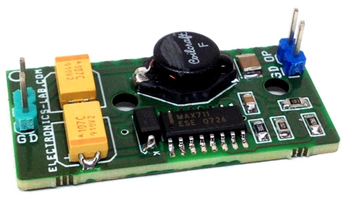
Photos

Video

MAX711 Datasheet

2.7A PWM Valve/Solenoid Driver Arduino Nano Shield

This Arduino shield helps to drive various loads like a solenoid, valve, motor, inductive actuator, heater, and bulb. A wide supply range 8V-60V and a load current of 2.7A allows it to be used with a variety of actuators. The board can be used as a stand-alone driver or it can be controlled by Arduino Nano. DRV102 is the heart of the project which is a high-side power switch employing a pulse-width modulated (PWM) output. Its rugged design is optimized for driving electromechanical devices such as valves, solenoids, relays, actuators, and positioners. The circuit is also ideal for driving thermal devices such as heaters and lamps. PWM operation conserves power and reduces heat rise in the device, resulting in higher reliability.

2.7A PWM Valve/Solenoid Driver Arduino Nano Shield – [Link]

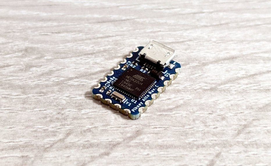
Piskey Atto is a Tiny Arduino Compatible Board with USB

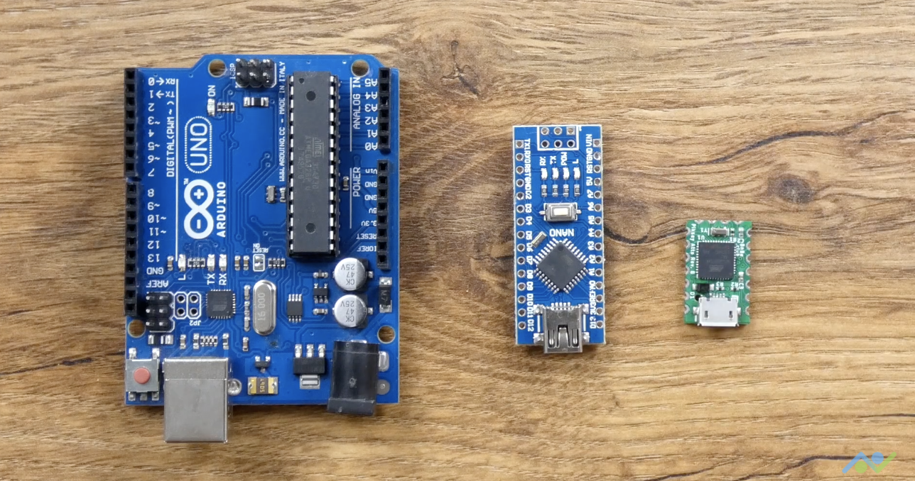
Designed with makers in mind, this cost-effective Piskey Atto handles most of the issues developers face with some of the available development boards.

“We recently started creating DIY projects on our YouTube channel and we ran into a similar issue, time and again. Most of the sensors and modules that we commonly use are already very small in size but the Arduino compatible boards used to drive them were not so much. There are some development boards that are small in size but they all seem to have one issue or the other – either they do not have enough I/O pins, are not powerful enough, or lack native USB support which limits the overall capabilities. We designed Piksey Atto to take care of these issues while also making it cheap enough to leave in projects.”

says BitsNBlogs Electronics, as they tell the story behind the Piskey Atto.

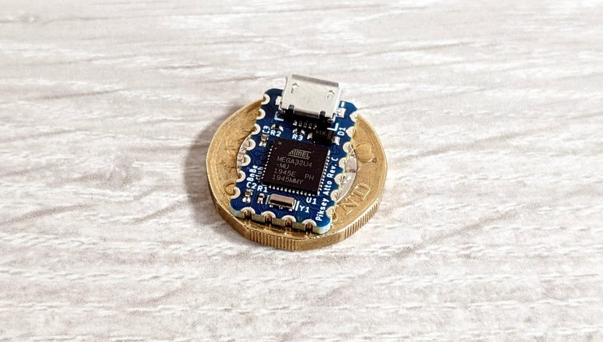
Smaller than a dollar coin, the Atto has everything you need for your projects: a built-in USB support that allows interaction with PCs, breadboard compatibility, and castellated holes that make it easier to be used with protoboard or soldered to your own baseboard.

The Atto has some impressive specs which include:

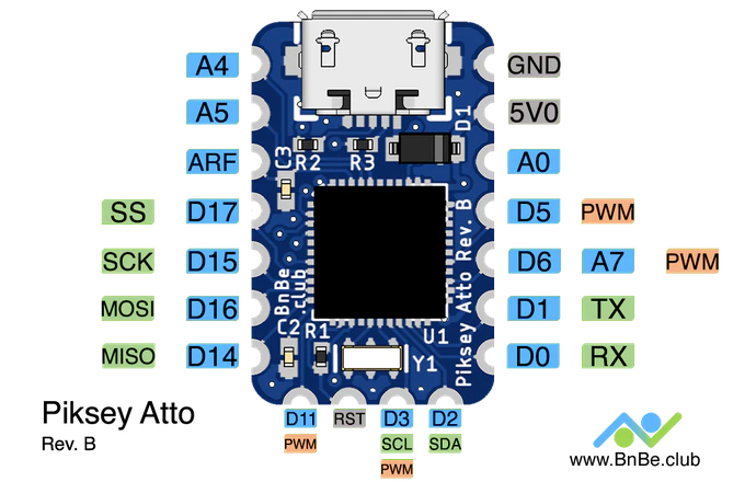
  • Microcontroller Unit: ATmega32U4 microcontroller running at 16 MHz, 2.5KB SRAM, 32 KB Flash memory and 1KB EEPROM
  • 11 digital I/O pins,4x analog inputs, 4x PWM
  • Built-in micro USB port for programming and power @ 5V
  • Communication: USART/SPI/12C
  • Power supply: 5V
  • Weight: 1.3 grams
  • Dimension: 12.70mm x 20.32 mm (0.5” x 0.8”)
  • Works out of the box with Arduino IDE 1.0+ (Win/OSX/Linux)

The Atto uses the same Atmega32U4 microcontroller chip found in the Arduino Leonardo and Arduino Micro so there is no need to install any board support packages as the board is compatible with all existing sketches and can work out of the box.

So far so good, BnBe Club says it has been able to use the Atto with PCB to create a nice little RGB LED coaster and also as a MIDI device, but the board is not out for sale yet. More information on how the Atto was built including design files, sketches, and demo projects can be found on Kickstarter where the campaign for the Atto has been launched with a $9100 goal. Rewards are expected to start shipping to any part of the world in June 2020.

New TQ platform based on Layerscape Dual Cortex-A72 technology

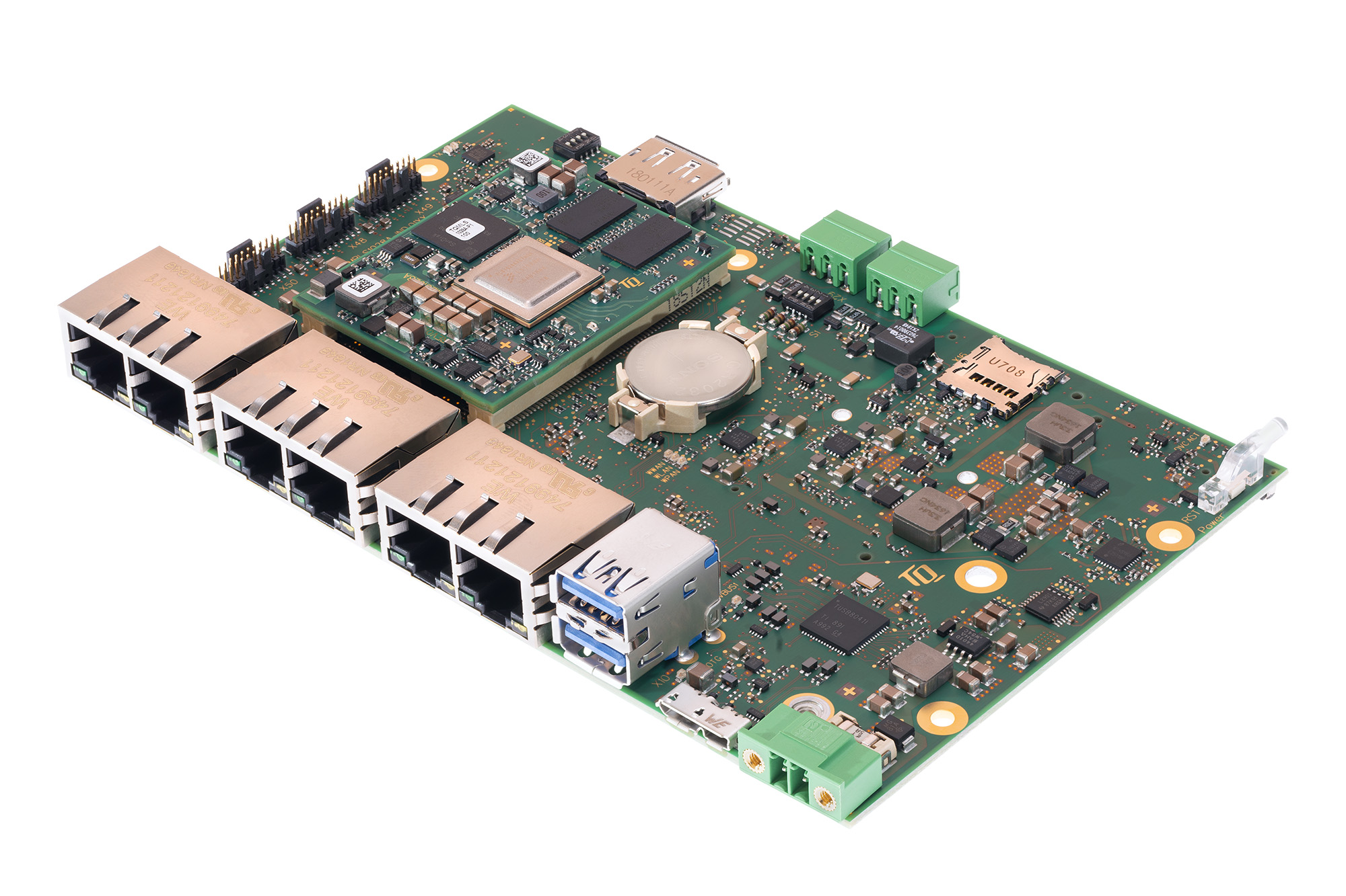
The technology company TQ is expanding its product portfolio with a new platform based on the 64-bit Cortex®-A72 QorIQ® Layerscape® processor family LS1028A from NXP. The MBLS1028A-IND is particularly suitable for robust and industrial applications in the field of high-speed data communication and offers TSN support in combination with powerful graphics.

The core of the platform, which is available both as a mainboard and as a complete device, is the TQMLS1028A module. For the TQMLS1028A, TQ relies on the NXP processor family Arm® Layerscape LS1028A. Based on this CPU, four different pin-compatible CPU variants are available depending on the required functionality. Alternatively to the two single-core variants (LS1017A and LS1018A), the dual-core variants (LS1027A and LS1028A) are available. The CPUs LS1017A and LS1027A have deactivated graphic functions. The integrated graphics of the LS1018A and LS1028A support displays up to 4K resolution with a powerful GPU. Combined with a clock rate of up to 1.3 GHz, the TQMLS1028A provides a comprehensive and scalable platform with low power dissipation.

Four Gigabit Ethernet interfaces are available on the mainboard with compact dimensions of 160 x 100 mm for fast data communication, which are implemented via a TSN-capable Ethernet switch. Additionally, users can rely on two independent interfaces for Gigabit Ethernet.

In addition to the Ethernet interfaces, the user has an M.2 SATA for connecting an SSD and a Mini PCIe slot with SIM card for expansion for wireless solutions such as LoRaWan, Sigfox, WiFi and mobile communication. In addition, two USB 3.0 interfaces and two galvanically isolated CAN interfaces are available. The embedded DisplayPort allows the connection of a monitor for a screen resolution of up to 4K.

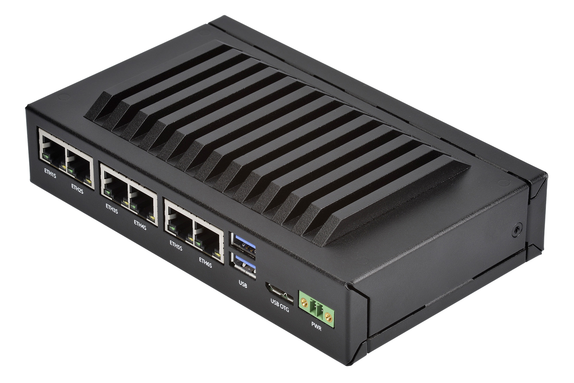
The design of the MBLS1028A-IND includes sufficient high-speed interfaces for the use in applications such as a TSN switch, edge server, Ethernet gateway or an industrial router. In combination with an enclosure, the MBLS1028A-IND works as a Box PC.

The platform guarantees a fast, secure and real-time capable data communication in combination with low power dissipation. The MBLS1028A-IND also works in robust and industrial applications in the field of high-speed data communication, automation and control systems.

The MBLS1028A is now available.

TQ-Embedded presents new high-speed module With NXP’s LX2160A

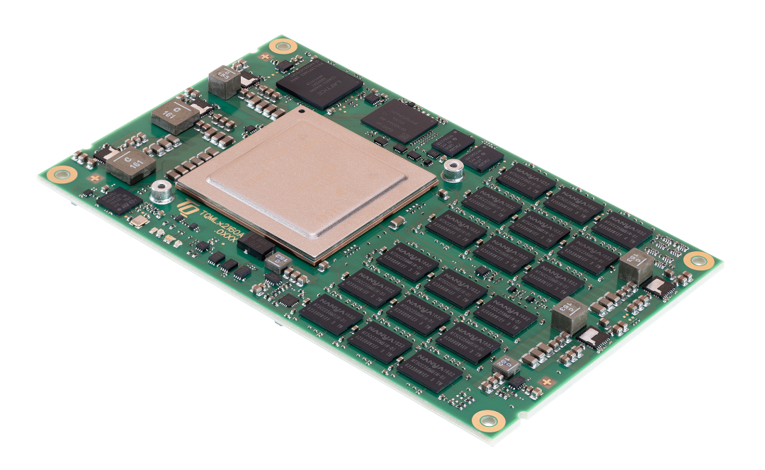
The technology company TQ presents the new embedded module TQMLX2160A based on the LX2160A CPU from NXP. The 64-bit QorIQ® Layerscape® processor family is particularly suitable for high-speed data communication. The first prototypes will be available from mid-June.

The TQMLX2160A relies on the NXP processor family Arm® Layerscape LX2160A. Depending on the required functionality, there is a choice of three CPU variants with either 8, 12 or 16 Cortex-A72. The pin-compatible CPUs (LX2160AA, LX2120 and LX2080A) with a clock rate of up to 2.2 GHz differ only in the number of cores.

For fast data communication, the compact dimensions of 126 x 78 mm integrate two interfaces for up to 100 Gigabit Ethernet. All 560 signal pins are available. In addition to 24x SerDes lanes with up to 25 GHz, which can be used as Ethernet, SATA and PCIe, the module has the following additional interfaces: up to 2x Gigabit Ethernet, 2x USB 3.0 2x CAN FD, up to 6x I²C, and 3x SPI.

The design is equipped with a DDR4 SDRAM memory with up to 64 GB with ECC support and up to 64 GB eMMC. The soldered RAM memory withstands even harsh environmental conditions. In addition, a QSPI NOR flash with up to 512 MB is used.

On the corresponding mainboard, users can use two 10 Gigabit Ethernet interfaces as well as one 100 Gigabit interface in addition to up to ten Gigabit interfaces. USB 3.0, CAN FD, SATA and PCIe interfaces are also available.

With this design, TQ-Embedded proves that it can support its customers in all challenges in the area of fast data communication and an expanded network technology. The module is suitable for network infrastructures where there are increased requirements for data transmission and processing. Further possible applications are servers, edge computers, transport and traffic engineering, as well as everywhere where there is a greater challenge in data processing with consideration of the lowest possible power dissipation.

2.7A PWM Valve/Solenoid Driver Arduino Nano Shield

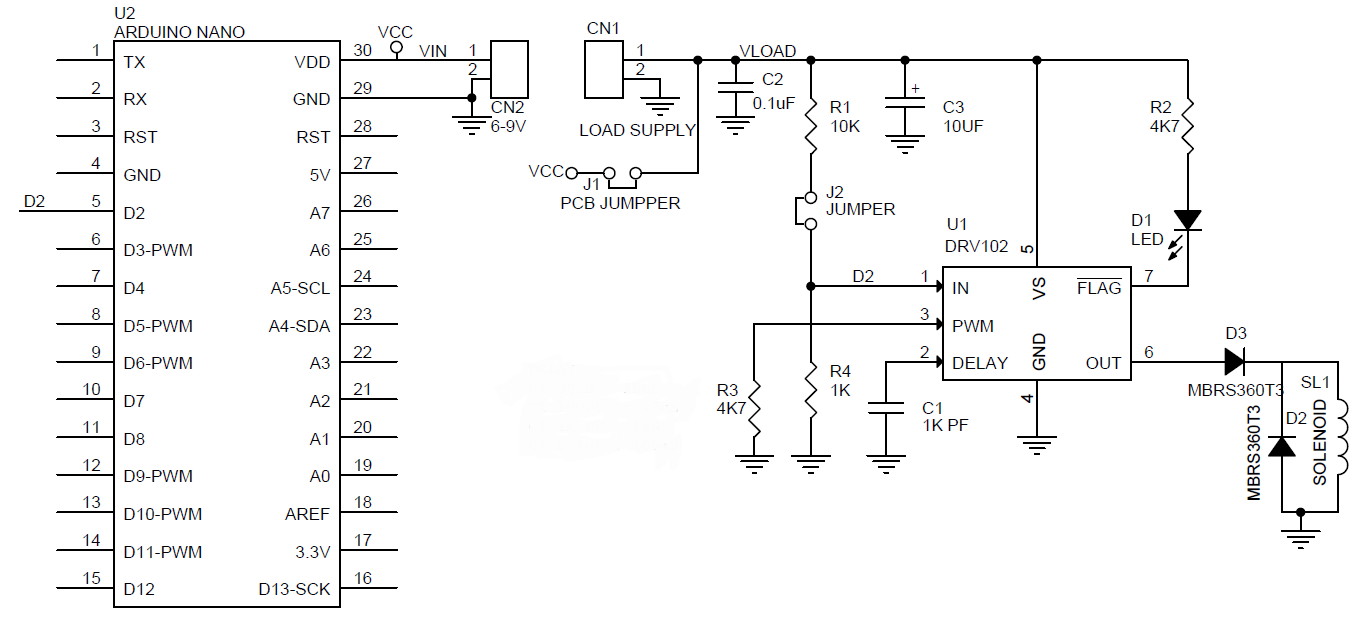
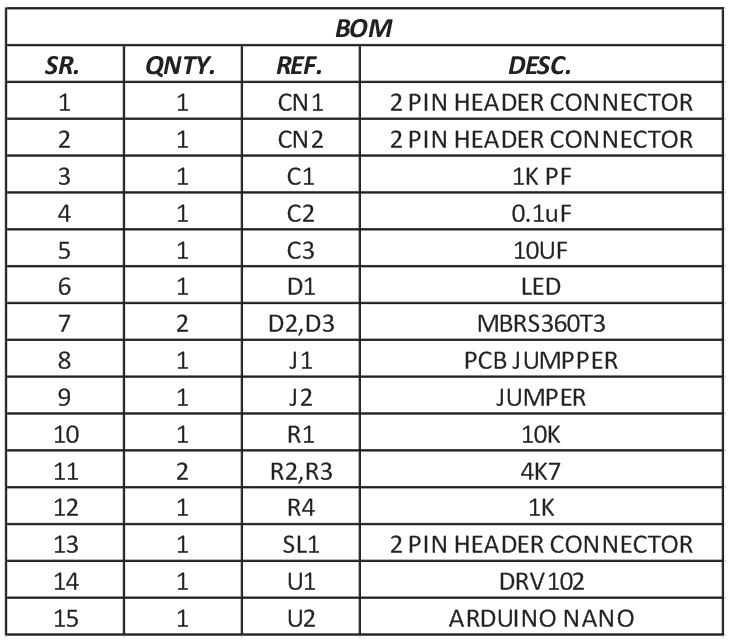
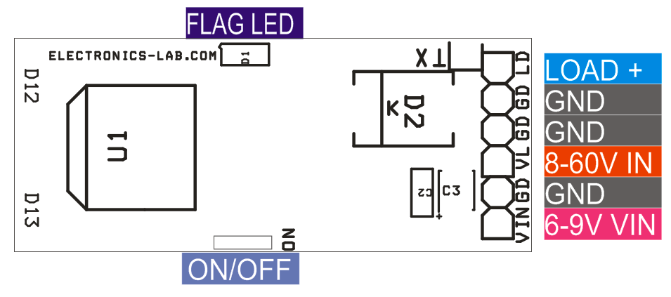
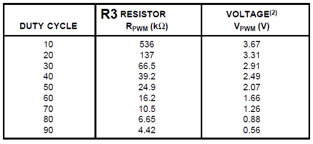
This Arduino shield helps to drive various loads like a solenoid, valve, motor, inductive actuator, heater, and bulb. A wide supply range 8V-60V and a load current of 2.7A allows it to be used with a variety of actuators. The board can be used as a stand-alone driver or it can be controlled by Arduino Nano. DRV102 is the heart of the project which is a high-side power switch employing a pulse-width modulated (PWM) output. Its rugged design is optimized for driving electromechanical devices such as valves, solenoids, relays, actuators, and positioners. The circuit is also ideal for driving thermal devices such as heaters and lamps. PWM operation conserves power and reduces heat rise in the device, resulting in higher reliability. In addition, adjustable PWM allows fine control of the power delivered to the load. the delay from DC output to PWM output is externally adjustable using C1 capacitor.  The DRV102 can be set to provide a strong initial closure, automatically switching to a soft hold mode for power saving. The duty cycle can be controlled by resistor R3. LED D1 output indicates thermal shutdown and over/under current limit. D2 of the Arduino Nano connected to the input of DRV102 to control on/off of the load, J2 jumper can be used to on/off the load in stand-alone mode, J1 PCB jumper provided to run the project with a maximum signal supply of 9V. The project requires dual supply, Load supply 8-60V and logic supply 6-9V.

Note : The board is set for 0.97mS delay on/off and can be altered for other delay using C1, Default duty cycle is 90% and can be altered using R3.

Features

  • Load Supply 8-60V
  • Logic Supply Arduino Nano 6-9V DC (Not Required In Stand-Alone Mode)
  • Load Current 2.7A
  • Delay On/Off Adjustable 15uS-97mSeconds (C1-Capacitor)
  • PWM Duty Cycle Adjustable ( 10-90%)
  • D1 LED Flag Indicator (Fault LED)

Schematic

Parts List

Connections

Delay Adjust

Duty Cycle Adjust

Photos


Video

DRV102 Datasheet

Sparkfun Launches Auto pHATs and Top pHats for Robotics and Display

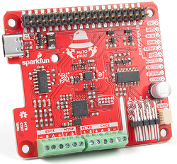
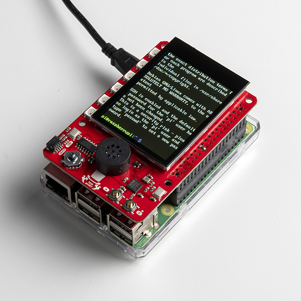
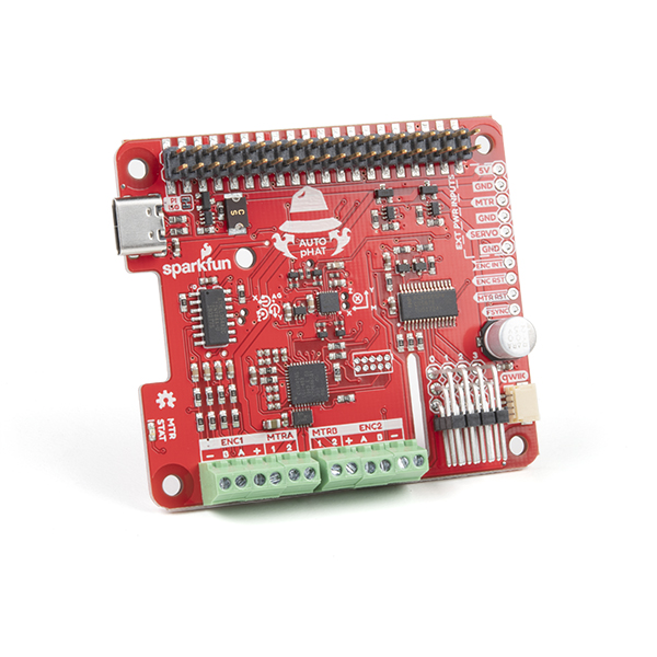
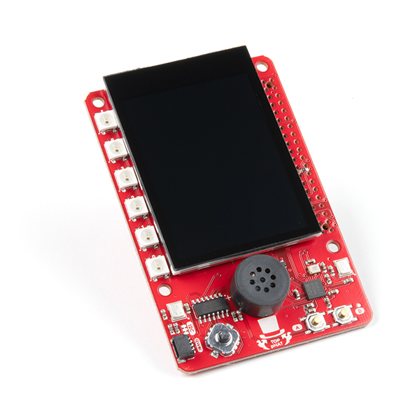
Available for sale at $29.95 and $49.95 respectively, the two new add-on boards recently launched by the Colorado-based Sparkfun for your Raspberry Pi, Jetson Nano and Google Coral development platforms can quickly add functionality and support to your single board computers without soldering: the Auto pHAT, all-in-one package for robotic controls and Top pHAT display board, perfect for implementing most machine learning applications that the Pi 4, Google Coral and Jetson Nano excel at.

While the Auto pHAT is feature-packed with motor and servo drivers for robotics and IMU for motor sense, the top pHAT has a 2.3-inch color display, LEDs, mic, buttons, and speaker for ML prototyping.

Auto pHAT

The Auto pHAT is capable of driving two small DC motors with or without encoders as well it supports up to 4 servo motors via 12C. Its servo control is based on a PWM-enabled servo pHAT with an I2C capability that saves the Raspberry Pi’s GPIO pins, allowing them to be used for other purposes. Hence, a unique robotics addition for boards with a 40-pin GPIO connector whether you use it with a Raspberry Pi, Google Coral, NVIDIA Jetson Nano, or any other single-board computer.

The Auto pHAT also has an ICM-20948 9DOF IMU for motor sense, where there are about 4 selected ranges from both the 3-axis gyroscope and 3-axis accelerometer alongside a 3-axis magnetometer. The power supply can be supplied in two ways: either a USB Type-C connector is used to power the pHAT as well as the Raspberry Pi connected to it or the pHAT is powered through the Pi’s GPIO and use the USB port to establish a serial connector with the Pi.

Top pHAT

The Top pHAT, on the other hand, is a UI interface and control panel for Raspberry Pi projects. Though it lacks the 40-pin passthrough, the pHAT is equipped with incredible features like a color TFT display, dual user buttons, programmable joystick for robotic control and GUI, Qwiic connector, 6x LEDs, 2x microphones, mono speaker and an off switch that makes it perfect for machine learning, camera control feedback, voice control, and system status display applications. Just like the Auto pHAT, the Top pHAT does not disturb access to the Pi’s camera or display connectors.

They are both are open source hardware modules and more information can be found on SparkFun’s news. The Auto pHAT is currently available on its shopping page while the Top pHAT is still on pre-order with shipments scheduled to start very soon.

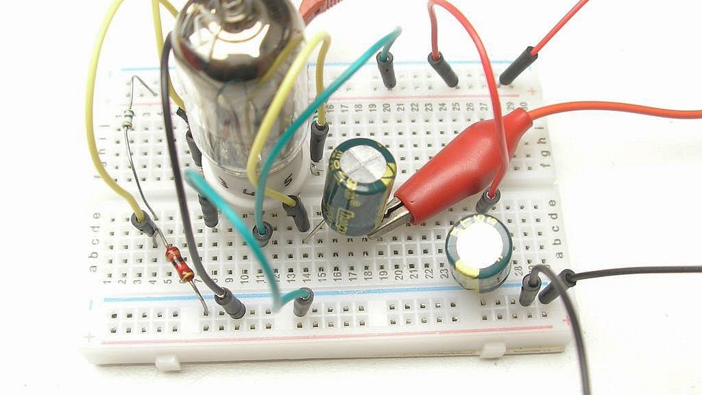
Vacuum Tube Pre-amplifier Runs Entirely on 3.3V, inclusive of filament voltage

Most vacuum tubes need about 6.3V high supply plus filament voltage to operate. Running at 3.3V inclusively of the filament voltage, the new vacuum tube amplifier from Albert van Dalen has proven it possible to have one with the capacity to operate on an entirely low power supply voltage and still work well.

“To be able to do experiments with vacuum tubes, I bought a cheap DIY 6J1 tube amplifier on Ali Express. Like most vacuum tube circuits, it uses a relatively high supply voltage of 60V. However, a high voltage is not always required for vacuum tubes, sometimes 12V is used. I was curious how far one can go with reducing the power supply. Nowadays the most common used power supply voltage for electronics is 3.3V and before this was 5V.” says van Dalen as he explains how he started with his design and was able to gradually decrease the voltage going from 60 V to 12 V to 5 V and then finally down to 3.3V partly by using a grid bias that looks like a bipolar transistor instead of the usual single-ended design.

Van Dalen also added that asides being able to work with a low supply voltage, power the preamp can also be used for audio purposes and can easily be powered from a USB.

“Tube amplifiers are used for nostalgia reasons and to get the characteristic tube sound. For this purpose, this preamp is useful, and you can simply power it from USB. The gain is -3.5 and music sounds undistorted. Just the red light from the filament is dimmed.”

However, some of the oddities caused by this very low supply voltage as observed by van Dalen in his experiment included a positive grid-cathode voltage instead of being negative and a very high grid current of 0.3 mA.

Seeing how much power he was able to reduce was a very big feat for van Dalen as the results so far have been very promising. Hopefully, more amplifier designs are likely to integrate the concept of this design in the nearest future.

If you are interested in making one for yourself,  you can check out the detailed step by step process of Albert van Dalen’s experiment on his website.

TOP PCB Companies