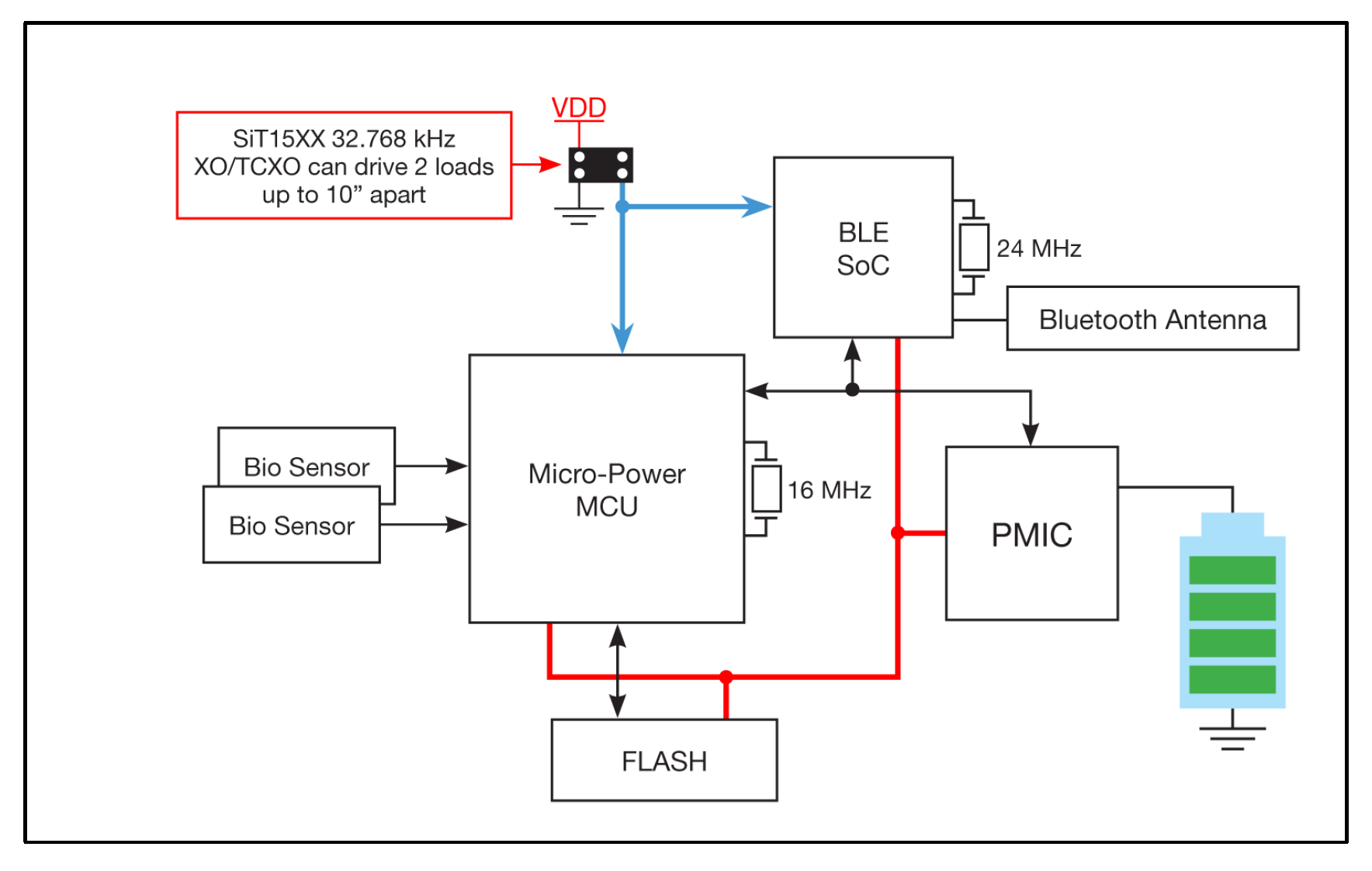
Driving multiple loads from a single oscillator output discussed in this app note from SiTime.
Optimizing board space and managing power consumption of wearable devices is critical in sustaining competitiveness within this fast growing consumer segment. With less power consumed, battery life is extended or provides the option to reduce the battery size. MEMSbased reference clocks offer an alternate to traditional quartz crystal timekeeping components, with advantages including a significant footprint reduction, improved accuracy, and lower system power. In addition, the capability to drive multiple loads with one ultra-small, nano-power oscillator is one way in which MEMS are supporting these improvements.
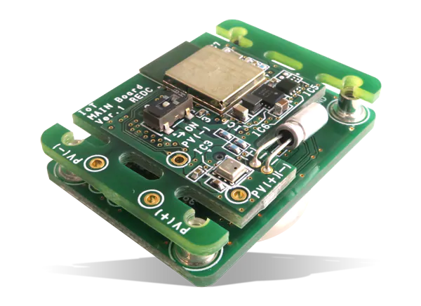
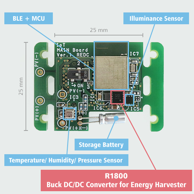
Ricoh Electronic Devices Company RIOT-001 Environment Sensing Board is designed to transmit data obtained from a temperature/humidity/pressure sensor (BME280) and an ambient light sensor (MAX44009) via Bluetooth, to tablets or other smart devices. The board also includes a voltage regulator with a battery monitor (RP124) for the measurement of the secondary battery voltage.
The RIOT-001 Board is ideal for indoor lighting using a solar battery panel. The RIOT-001 Environment Sensing Board efficiently harvests the electric power a solar battery panel generates. This happens using the buck DC/DC converter for energy harvest then stored in a small Li-ion secondary battery. The stored power is supplied to a BLE module with an MCU and sensors by the RP604, an ultra-low supply current buck-boost DC/DC converter.
The RIOT-001 Board also includes the RP124, a voltage regulator with a battery monitor, to monitor the secondary battery voltage. Checking the state of the secondary battery voltage is possible by transmitting battery information to tablets or other smart devices through an AD converter inside the BLE module.
RIOT-C01 Coin Battery Board
The RIOT-C01 Coin Battery Board is an optional board for the RIOT-001 environment sensing board. This board features a battery holder for a CR2032-type coin battery. The RIOT-C01 board charges the secondary battery mounted on the RIOT-001 that provides the environment sensing operation with a coin battery.
Specifications
Input voltage of 2.0V to 5.5V
Max. power voltage of 4.4V
Output voltage of 1.79V to 2.03V
Secondary battery charging voltage of 2.62V to 2.78V
I’m quite passionate about air quality monitoring, so whenever I see an interesting air quality monitoring project that could help people stay healthy, while also serving as a good way to learn DIY electronics, I’m always eager to share. Thus, for today’s tutorial, I will chronicle the build process of an Indoor Air Quality Monitoring system developed and shared on Hackster by Roman Novosad.
The device developed by Roman determines air quality by monitoring and displaying the amount of CO2, TVOC, and particulate matter in the air. It also monitors other parameters like air pressure, temperature, and humidity to ensure that the user is aware of their environment at all times. Unlike most air quality monitoring solutions, Roman’s project is designed for indoor use, which if we all think about it, is quite important as people typically spend 60 percent of their time indoors, and can directly influence the conditions to make it more conducive, unlike in outdoor situations.
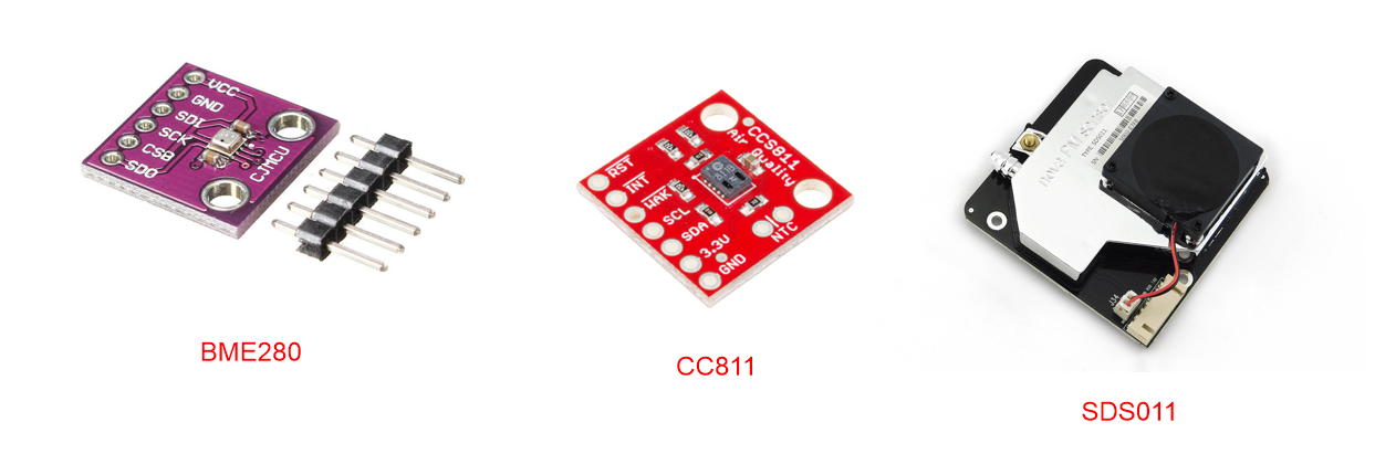
The project makes use of high-quality sensitive sensors like the BME280, the CC811, and the SDS011. The BME280 is used to monitor the temperature, humidity, and atmospheric pressure in the environment while CC811 is used to measure the amount of CO2 and the total amount of volatile compounds (TVOC) in the environment. The SDS011 is used to monitor particulate matter ( PM2.5 and PM10), and data from all the sensors are displayed on a 5″ touch-screen, to provide visual feedback to users.
To process the information from the sensors and display them, the project makes use of the NXP i.MX7 SOM based PICO-Pi-i.MX7 from Wandaboards. The Pico-PI-iMX7, thanks to the i.MX7 features a dual-core processor comprising of the ARM Cortex A7 and Cortex M4 processors. The board maintains a pin-out arrangement and form factor similar to that of the Raspberry Pi and possesses communication features like WiFi, Bluetooth, and Ethernet among others. A datasheet listing all the features of the board. To make the board easy to use, Wandaboard packages it as a kit with a display and other useful accessories. The kit is what will be used for today’s tutorial.
Pico-Pi-i.MX7 kit
At the end of this tutorial, alongside being able to replicate the project, you would have learned how to work with a board like the Pico-pi-i.MX7 and also use some of the sensors.
Required Components
As mentioned above, the following components are required to build this project;
All components can be bought from the links attached to them.
For the enclosure, while Roman created one for the project, you can decide to design yours and choose an attachment option (number 8 above) that suits you. If you will, however, use the enclosure designed by Roman, then ensure to get the M2.5 screws along with other components.
Asides the hardware components, the project also has some software requirements which include having an Android Studio installed on your computer as it will be used in uploading the software to the board.
Schematics
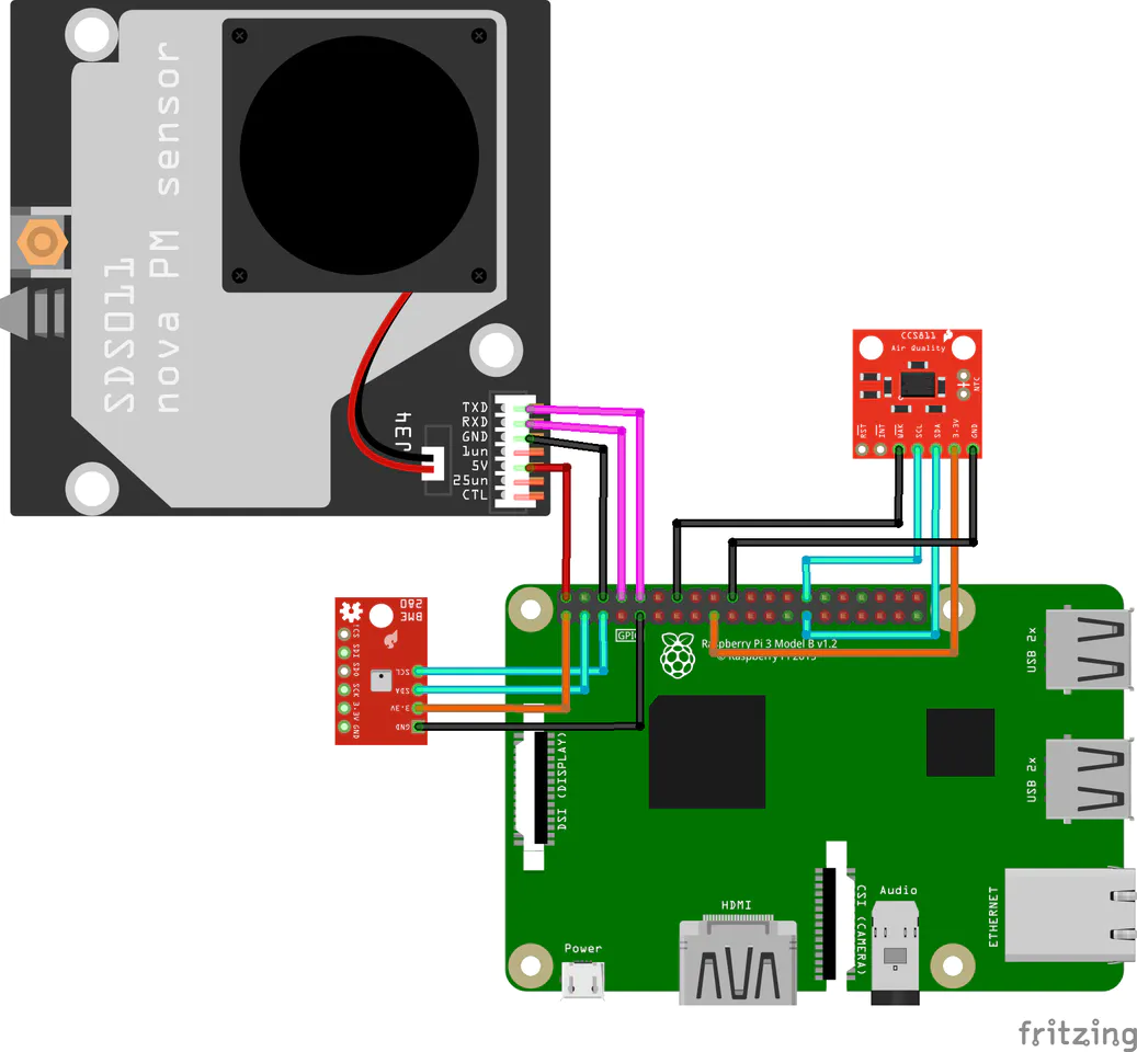
Connect the sensors to the Pico-Pi-i.MX7 as shown in the image below.
Notice the Raspberry Pi was used in the schematics? A model for the Pico-Pi-i.MX7 is not available on fritzing, so, the one for the Raspberry Pi was used since the iMX7 and the PI share the same pinout configuration. To get a better understanding of the connections and verify the relationship between the pinout of the Raspberry Pi and iMX17, you can check out this description of the iMX17 board.
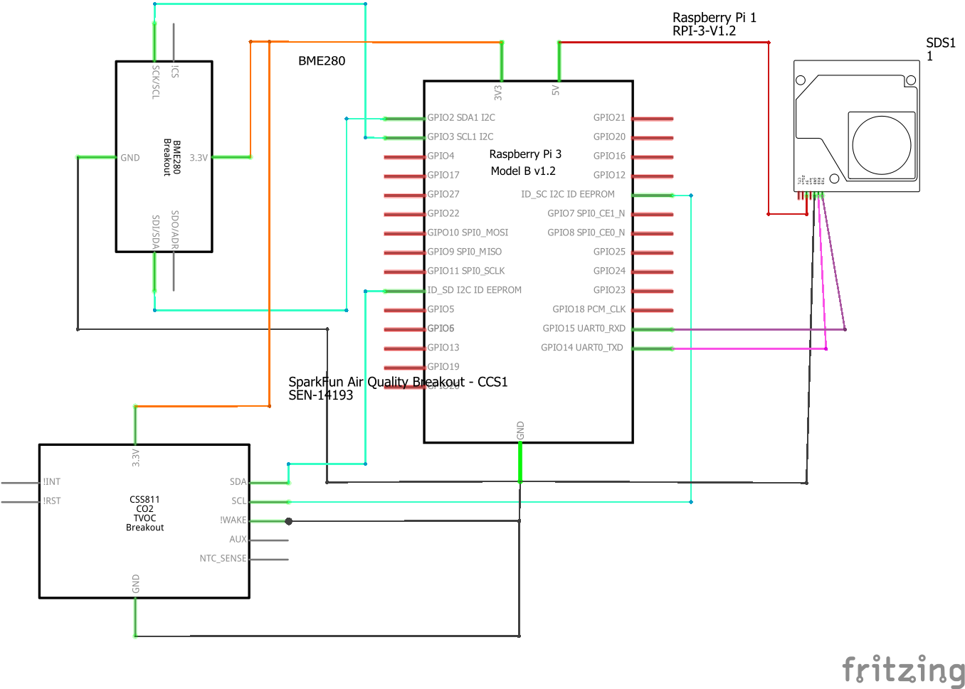
To make the schematics easier to follow, another view of the connection is provided below:
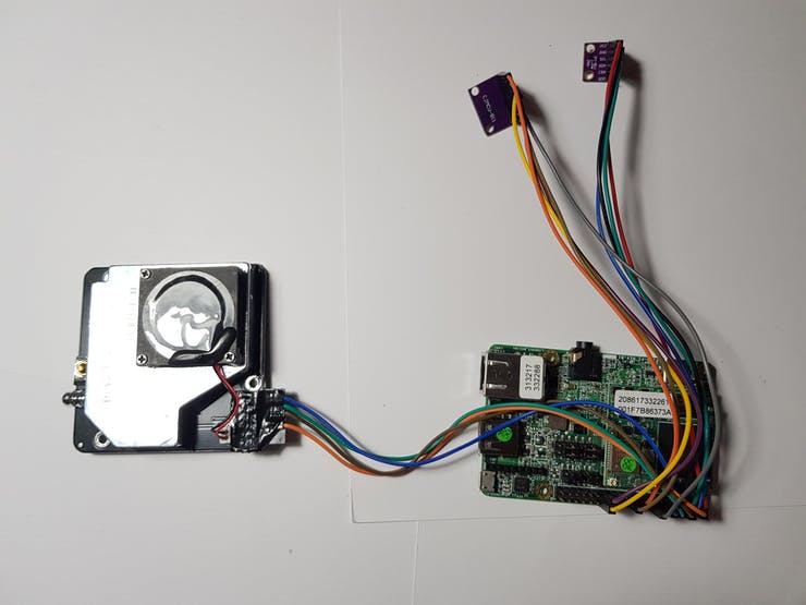
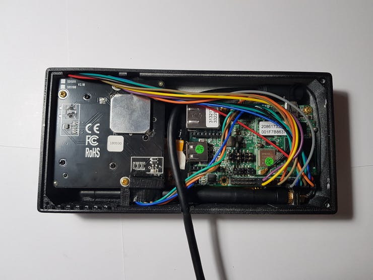
After connecting the sensors, the setup should look like the image below.
With everything in place, connect the other accessories(screen, etc.,) to the Pico-Pi. The setup after this has been done should look like the image below;
With this done, we are now ready to FLASH the device with the project’s firmware.
Install the software
The IMX7 SOM comes with the Android Things OS preloaded out of the box, as such, the easy path to programming the board is via Android Studio. So if you are yet to install it, now it will be a good time to do that.
With your Android Studio installed, plug the USB Cable to the Pico-Pi and to your computer. The Pico-Pi should begin its boot process and when complete, you should see a screen that tells you the device name and the wireless network to which it is connected (even though that is not needed for this tutorial).
The software for the project is already precompiled as an application by Roman, so all we need to do is to install that software on the Pico-Pi-i.MX7. However, before the application is installed, it is important to ensure no other application has been previously installed on the Pico-Pi.
You can check if a previous application has been installed, you can uninstall it (using a Windows computer) by:
Accessing C:\Users\,<YOUR_USER>\AppData\Local\Android\Sdk\platform-tools> via cmd
Then type adb root to get root access to the IMX7.
Next, run adb shell, followed by cd data/app and ls to see all the packages installed on the machine.
If there is an application installed, Copy the name (i.e. everything before the “-“) and Type exit.
Next, uninstall the app you discovered by typing adb uninstall <NAME_YOU_COPIED>.
With this done, the existing app would be uninstalled and you can proceed with installing the App by Roman.
To install the needed APP, launch Android Studio on your PC and load the app files into your workspace by accessing them from the projects GitHub page via version control.
With the app loaded, Android Studio should automatically detect the connected Pico-Pi-i.MX7 board and you should be able to run the project on it by pressing ‘Run’. When you do this and the project runs successfully, the app will be installed on the Pico Pi and will stay on it even if you disconnect the SOM from the computer.
Demo
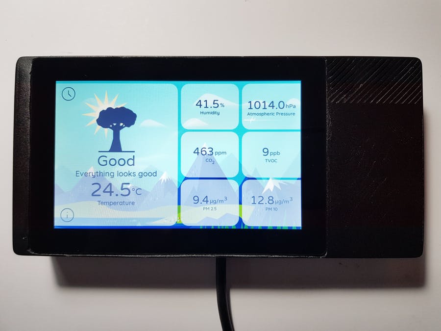
With the App installed, disconnect the device from the computer and power using a battery or over USB. You should see the device boot up and the screen comes up with the sensor values as shown in the image below.
Demo
The values of CO2 and TVOC may vary arbitrarily initially, but after a while, it should settle and become consistent.
By default, the screen is updated with sensor data every (1) second but you can change this option on the screen to increase the time by clicking on the clock icon. You can also choose to see more information about the measurement among other things by clicking the information icon.
Enclosure
To make the project compact and pleasing to the eyes, Roman created a 3D printed enclosure for the project. The design and STL Files are attached under the download section below. Feel free to modify to suit your taste. The device after assembling in the enclosure is shown in the image below.
That’s it! Your very own Indoor Air Quality Monitor.
There are different modifications that could be made to this project. You could decide to add alarms with a buzzer, or connect the device to the internet to send you an email alert, or even populate an online dashboard. However, in the coming weeks, I will be creating an ESP32/Raspberry pi based version of the project with micro python since that is more popular and may be easier to manipulate. If you are interested in that version of the project drop a comment saying so!
This tutorial is a continuity of our last article about Thevenin’s theorem. In the previous article, we have seen that any linear electrical circuit can be simplified into an elementary circuit that consists of an ideal voltage source in series with resistors.
Another very similar model is known as Norton’s theorem, it has been established in 1926 by the American engineer Edward Norton, more than 70 years after the first version of Thevenin’s theorem.
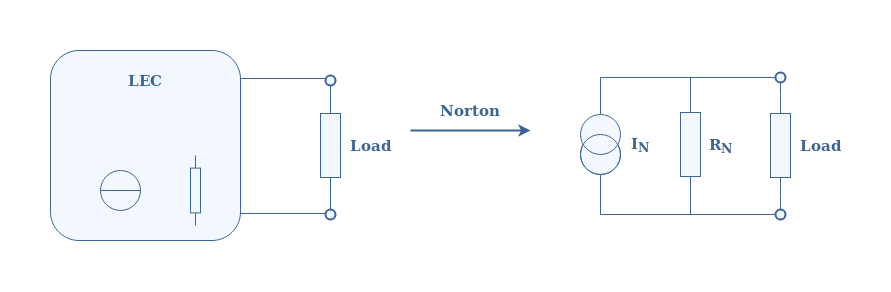
Norton’s theorem affirms that any linear electrical circuit is equivalent to an ideal current source in parallel with an equivalent resistor.
First of all, we give a recap concerning the bold terms of this sentence in order to understand the appropriate framework where this theorem applies. In the second section, we propose a step by step method to follow in order to determine Norton’s equivalent model of a circuit. Different real examples will be proposed in a third section in order to illustrate this method.
Finally, we will draw a link between Norton’s and Thevenin’s models, before concluding this tutorial.
Presentation and definitions
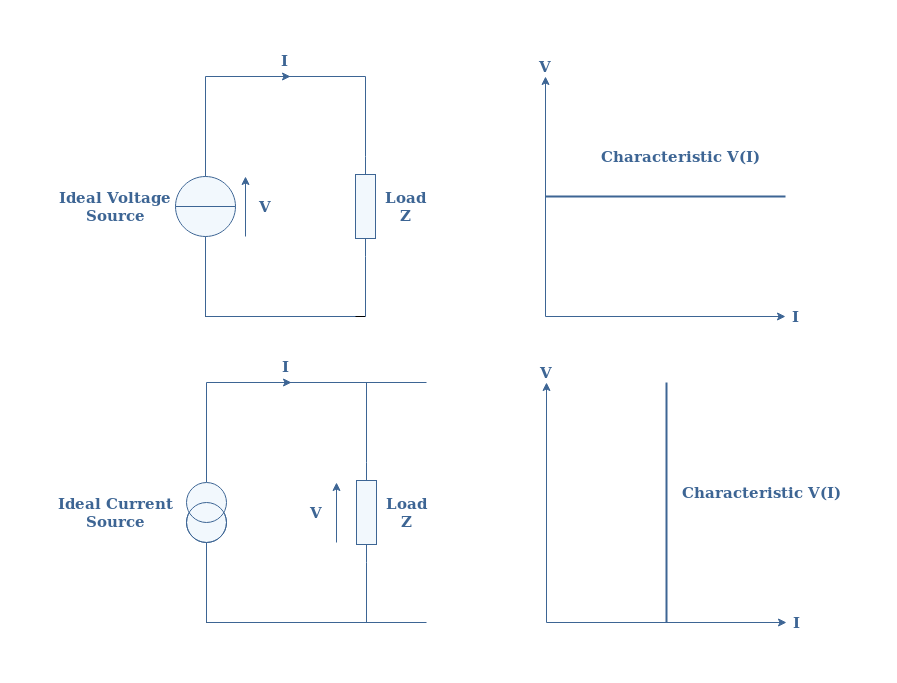
Linear electrical circuits (LEC) are the framework of Norton’s theorem and they represented a particular type of circuit in which the only components are ideal sources and resistors.
Ideal voltage (resp. current) sources provide a constant value of voltage (resp. current) regardless of the current flowing (resp. voltage) in the circuit. Their representation and behavior are illustrated in Figure 1 below:
fig 1: Representation and characteristics of the ideal sources
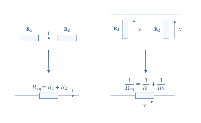
An equivalent resistor Req represents an association of a set of interconnected resistors. The rules to associate resistors together are illustrated in Figure2 below:
fig 2: Series and parallel resistor associations
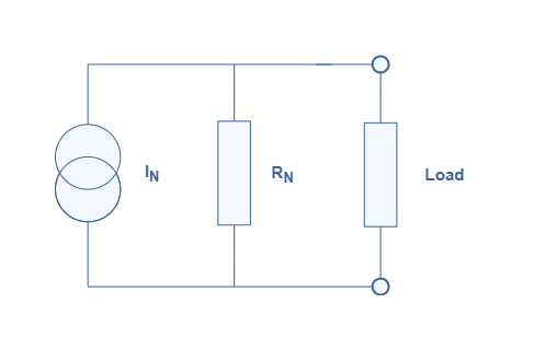
The framework and definition being now clear, we illustrate Norton’s theorem with the following Figure 3:
fig 3: Illustration of Norton’s transformation
Using Norton’s theorem on a LEC leads to a simple circuit known as Norton’s model composed of an ideal current source in parallel with resistors. The equivalent current source and resistor are labeled with the subscript N as a reference to the name of the theorem.
The next section abstractly presents the step-by-step method to follow in order to determine the Norton model of any LEC.
Norton model determination
Norton’s current INrepresents the current at the terminals of the LEC when the load is replaced by a wire, it is also known as the short-circuit current.
Norton’s resistance RN is, in fact, equal to the Thevenin resistance RTh, they both represent the resistance at the terminals of the LEC when all the LEC’s sources are deactivated: the voltage sources are shortened and the current sources opened.
We propose the following steps to respect in order to determine the Norton model of any LEC:
Replace the load at the terminals of the LEC by a wire
Compute the current of the shortened circuit
Replace any voltage sources with short-circuits and the current-sources with open-circuits
Compute the equivalent resistance
Reconnect the load and draw the Norton model thanks to the knowledge of IN and RN
The next section focuses on applying this method to real circuits, from the most elementary design to more complex architectures.
Norton’s model of some LEC
Single Voltage Source
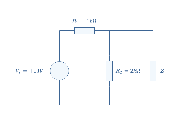
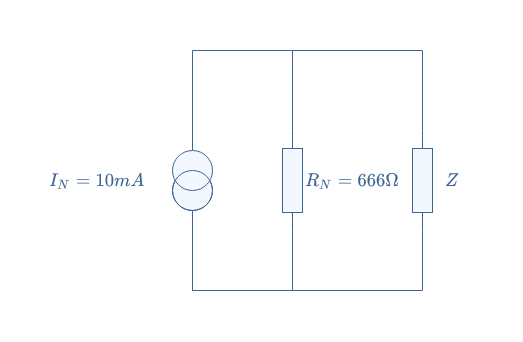
Consider the following circuit presented in Figure 4:
fig 4: Single voltage source LEC
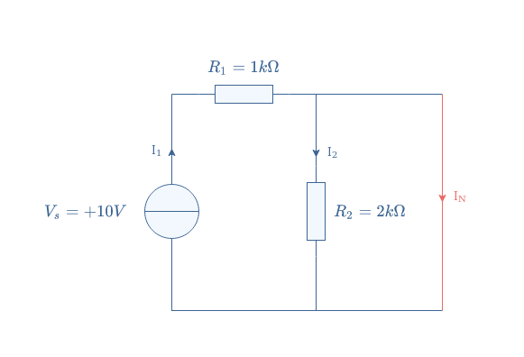
In order to determine the Norton model of this circuit, we remove the load Z and shorten the terminals of the circuit:
We can now determine the Norton current IN, Kirchoff’s current law states that I1=I2+IN. Since IN does not cross any impedances, which means that the resistor R2 is shortened, we can affirm that I2=0.
Norton’s current is therefore equal to the current delivered by the voltage source, it can be computed by applying Kirchoff’s voltage law: Vs=R1I1+R2I2=R1I1 ⇒ IN=Vs/R1=10 mA.
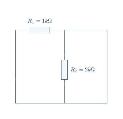
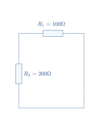
To find Norton’s resistance RN, we replace the voltage source by a wire:
In this configuration, R1 and R2 are in parallel, the equivalent resistance is therefore given by RN=(R1×R2)/(R1+R2)=666 Ω.
We can now give the Norton model of the circuit presented in Figure 4:
fig 5: Norton’s model of the single voltage source LEC
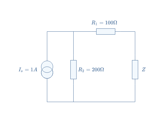
Single Current Source
We consider a similar example than in the previous subsection by replacing the voltage source by a current source:
fig 6: Single current source LEC
We proceed first by removing the load and shortening the terminals of the LEC. We label I2 the current across the resistor R2 and I1=IN the current across the resistor R1. We simply find the Norton current by applying the current divider formula: IN=(R2/(R1+R2)×IS=0.7 A.
We replace the ideal current source by an open circuit in order to find Norton’s resistance:
The equivalent resistance is simply given by the series associations RN=R1+R2=300 Ω.
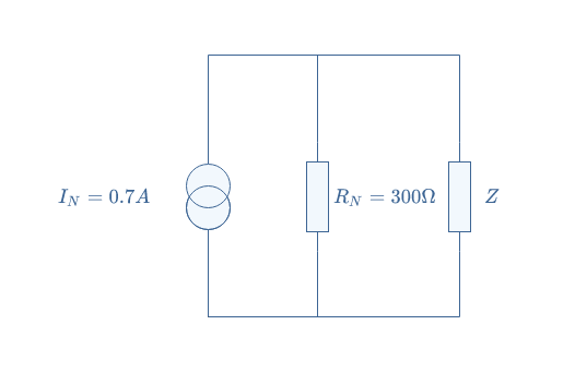
The Norton model of the LEC presented in Figure 6 is finally given by the following circuit:
fig 7: Norton’s model of the single current source LEC
Multi-current/voltage sources
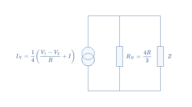
For the last example, we increase the complexity by including both current and voltage sources and more resistors in the same circuit. We consider the following LEC that we have already dealt with in our previous article concerning Thevenin’s Model:
We proceed again similarly by replacing the load Z with a wire in order to find Norton’s current. By applying Kirchoff’s current law, we get I=i1+i2+i3+IN. Moreover, by applying Kirchoff’s voltage law to every loop of the circuit, we get:
i1=i2+V1/R
i1=i3-V2/R
i1=IN
After rearranging these equations to express IN as a function of i1, i2, and i3 in each line, we can finally isolate Norton’s current and find: IN=(V1-V2)/4R+(I/4).
We have already demonstrated in the Thevenin theorem article that RTh=4R/3 and since RN=RTh, the Norton resistance is thus already known.
Norton’s model of this complex circuit is given in Figure 9 below:
fig 9: Norton’s model of the multi-source LEC
The link between Thevenin and Norton models
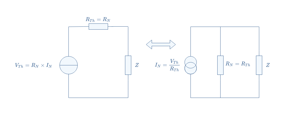
There is something very interesting to note about the multi-source example treated both in this article and the Thevenin tutorial. Indeed, if we proceed to the multiplication U=IN×RN, we find U=(RI+V1-V2)/3, it happens that this value is equal to the Thevenin equivalent voltage: IN×RN=VTh.
From the knowledge of Norton’s parameter, we can, therefore, find Thevenin’s parameters for the same circuit: RTh=RN and VTh=RN×IN. Reciprocally, the knowledge of Thevenin’s parameters can be converted into Norton’s parameters: RN=RTh and IN=VTh/RTh.
The conversion between a Theveninmodel to a Norton model or reciprocally lies only on one operation, we illustrate this conversion in Figure 10:
fig 10: Conversion procedure between Thevenin’s and Norton’s models
Conclusion
This tutorial has been built around one sentence, known as Norton’s theorem: “Any linear electrical circuit is equivalent to an ideal current source in parallel with an equivalent resistor“.
We have first presented the framework in which this theorem can be applied along with the definitions of some key concepts. We have seen that linear electrical circuits (LEC) consist of an interconnection of ideal sources and resistors. Ideal sources are well defined in the first section along with the equivalent resistance concept.
The second part is a short section that proposes a step-by-step method to follow in order to determine the Norton model of any LEC. The method is illustrated with real examples in a third section which proposes simple single-source circuits and finally a more complex architecture.
To conclude, we establish a link between Norton’s and Thevenin’s equivalent circuits by illustrating how to convert one model to another.
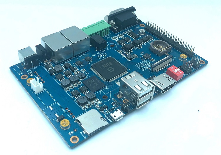
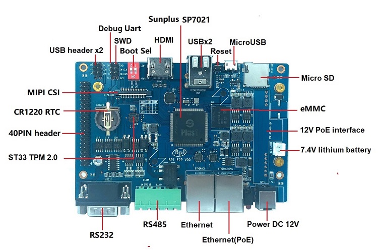
Banana Pi BPI-F2P uses Sunplus chip design, this is an industrial control board. use Plus1(sp7021) design same as Banana Pi BPI-F2S, it support PoE function with PoE module,and support RS232 and RS485 . so you can use it do an Industrial control gateway.
About SunPlus SP7021
SunPlus sp7021 is a revolutionary SoC that has the power of a Linux-grade chip and the integration simplicity of a microcontroller.it with ARM Cortex-A7 Quad core,ARM926 real-time core,8051 low-power core
Conceived by Sunplus Technology in collaboration with Tibbo Technology, PLUS1 takes all the sophisticated elements typically found in modern industrial-grade embedded Linux chips, adds a plethora of features targeting IoT and industrial control applications, and delivers the resulting design in a simple microcontroller-like package that needs few external components, simplifies the schematic diagram, and reduces the PCB complexity.
SP7021 is a SoC solution of industrial control. It meets customers’full demand on function but with low cost so that will improve customers’ competitiveness in the market. SP7021 provides rich GPIOs, storage and USB interface. And it provides MIPI CSI interface for video input and HDMI interface for video output. It also provides FPGA interface for function extension. SP7021 also has 4 Ethernet ports providing customers a high competitive solution.
Characteristics of the SP7021
Easy-to-use LQFP package.
Quad-core 1GHz Cortex-A7 CPU, plus A926 and 8051 cores.
Single 3.3V power*.
Integrated 128MB or 512MB DDR3 DRAM.
Eight 8-bit 5V-tolerant IO ports, plus one high-current port.
Flexible Peripheral Multiplexing (PinMux).
Dual PinMuxable Ethernet MACs.
Four PinMuxable Enhanced UARTs, plus one console UART.
Industrial operating temperature range: -40C ~ +85C.
Low EMI simplifies certification.
Modern, Yocto-based Linux distribution.
10-year supply guarantee.
Robust ready-to-run modern Linux distribution available
And much more…
Hardware specs
SoC – Sunplus SP7021 “Plus1” with a quad-core Cortex-A7 processor @ 1.0 GHz, one Arm A926 microprocessor, an 8051 core to handle I/Os, and 128MB or 512MB DDR3 DRAM.
Storage – 8GB eMMC flash, microSD card slot
Video Output – HDMI 1.4 output
Camera I/F – MIPI CSI connector
Connectivity – 2x 10/100M Ethernet
USB – 2x USB 2.0 host ports, 1x micro USB port
Expansion
2 USB header interface
40-pin GPIO header compatible
7.4V Lithium battery power supply interface
RTC battery interface
PoE function support
Debugging – 3-pin header for UART console, SWD ICE port
Security – TPM 2.0 via ST33TPH2EI2C secure element
Misc – Power switch, reset button, boot selection dip switch
In contrast to technology and science, in everyday life, a distinction is rarely made between regulation and control. A mere control system does not monitor the output value, meaning that it can change due to external disturbances. A simple and typical example is the speed control of a DC motor by PWM. Here, the speed of the motor is also influenced by load fluctuations.
Now to the control: If speed is to be kept constant, feedback is required, for example, to adjust a controlling PWM or DC voltage depending on the speed deviation. Such a feedback system characterizes a control loop.
Control, therefore, means that the output variable (e.g. speed) is captured and, in the event of a deviation from the target value, the manipulated variable (here the PWM) is changed accordingly.
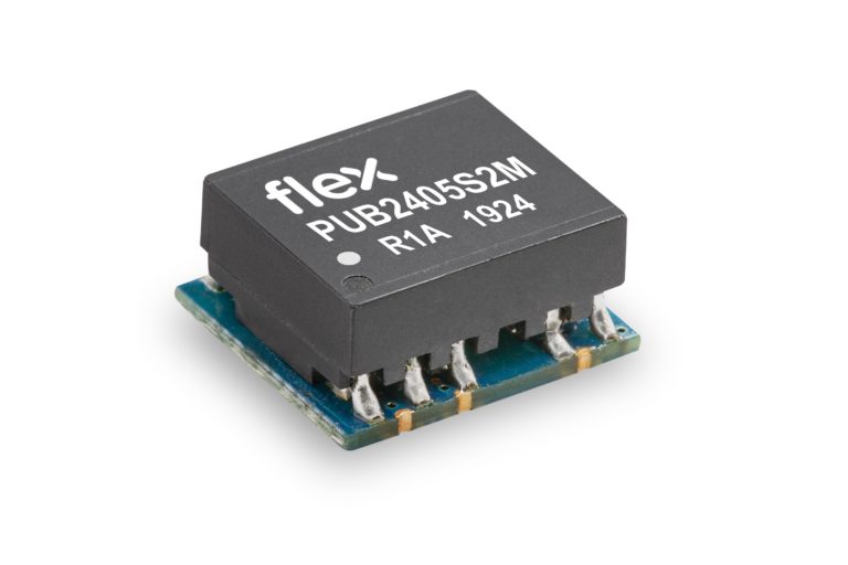
Flex Power Modules has added to its range of miniature isolated DC/DC converters intended for industrial applications with the introduction of the PUB-2M series. Delivering an output power of up to 2W with no minimum load required, the high performance product is available in single or dual output options.
Presented in a compact SMD (surface mount device) package measuring 12.75 x 11.2 x 8.0 mm (0.502 x 0.441 x 0.315 in) for single output and 15.25 x 11.2 x 8.0 mm (0.6 x 0.441 x 0.315 in) for dual output, the new unregulated DC/DC converters achieve a high efficiency, typically up to 86.5% with a 12V output under full load conditions.
The new family of isolated, unregulated DC/DC converter modules offers output short-circuit protection and MTBF figures of 17.9Mhrs. The robust converters are ideal for harsh environments common in industrial applications with a capability to reliably operate in temperatures ranging from -40°C to +110°C. The devices are safety compliant to EN/UL 62368-1, and Flex Power Modules is an ISO 9001/14001 certified supplier.
The launch of the PUB-2M series follows the company’s recently introduced PUC-2B, a series of 2W isolated, unregulated DC/DC converters with reinforced insulation for industrial applications that are housed in a compact SIP7 package.
For more information, the full datasheet of the PUB-2M is available here: flexpowermodules.com
This project has been developed to charge SLA (Lead Acid Batteries). It helps to charge 12V Lead-acid battery up to 12Ah in capacity. The specific current output is possible by altering the current sense resistor. The BQ24450 chip contains all the necessary circuitry to optimally control the charging of valve-regulated lead-acid batteries. The IC controls the charging current as well as the charging voltage to safely and efficiently charge the battery, maximizing battery capacity and life. Depending on the application, the IC can be configured as a simple constant-voltage float charge controller or a dual-voltage float-cum-boost charge controller.
The built-in precision voltage reference is especially temperature-compensated to track the characteristics of lead-acid cells and maintains optimum charging voltage over an extended temperature range without using any external components. The ICs low current consumption allows for accurate temperature monitoring by minimizing self-heating effects.
12V SLA Lead Acid Battery Charger Using BQ24450 – [Link]
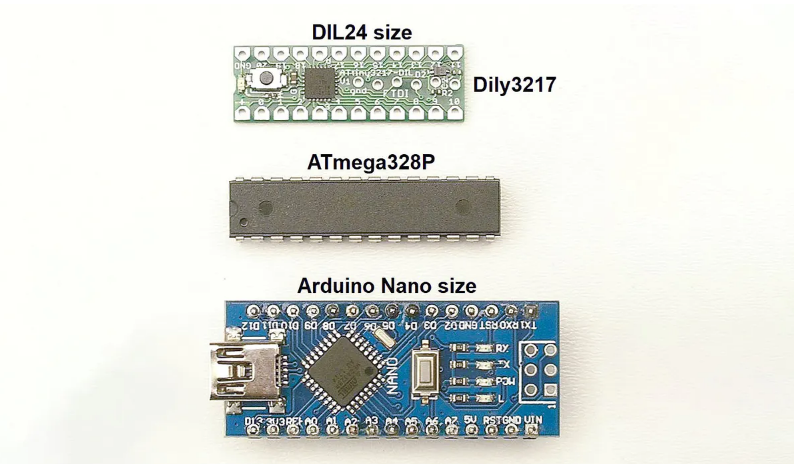
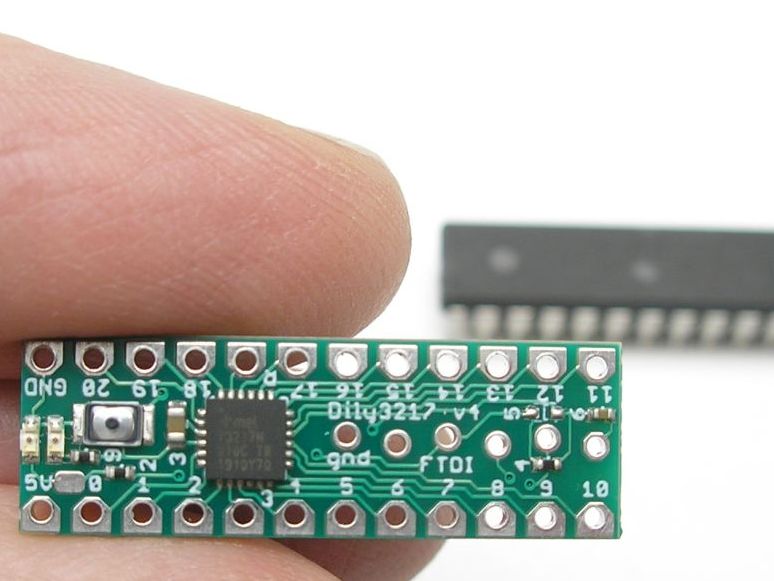
The new Dily3217 is a breadboard friendly Arduino compatible development board that is easy to integrate with more or less the same functionality as the Nano. Powered by a very small Atmel AVR chip, the Dily3217 copies virtually all the features of the already compact Arduino Nano into a board that is smaller than the ATmega328P itself.
Designer Albert van Dalen explains how a powerful member of the ATtiny series with large memory and hardware UART became the motivation behind the Dily3217.
“…Previously, the ATtiny chips don’t have enough memory and you could not debug them well because they don’t have a UART. Then, I discovered the ATtiny3217; it has been released in 2018. The ATtiny3217 has the most memory (32k/2048) and I/O pins (21) of the ATtiny series. And because of the QFN-24 package, the chip is extremely small. This chip is small and has about the same features as the ATmega328P. Because the chip is so small I immediately came up with the idea to make a narrow DIL24 design: the Dily3217.”
ATtiny3217 has the same 32 kilobytes program memory and over 2 kilobytes of SRAM just like the ATmega328P found in the Nano. Like other AVR MCUs, the 3217 also has GPIO pins, 21 in number operating at 5 volts, multiplexed for analog and digital functions.
In contrast to the Nano, the DL3217 uses an FTDI header for serial communication instead of an onboard USB support, and programming it via the Arduino IDE requires the Spence Konde’s mega TinyCore package.
OLYMPUS DIGITAL CAMERA
Some features of the DIL3217 board include:
Atmel ATtiny3217
Preloaded Bootloader Optiboot
Available 8-bit ADC in addition to the 10-bit DAC
FTDI connector
Internal 20MHz oscillator clocked @ 5 V
Power and Status LEDs
Reset buttons
Pin-out is direct and straight forward
1.8V to 5.5V voltage supply with an optional voltage regulator for supply more than 5.5V
With almost the same set of features as the Nano, the less than 300mm squared Dily3217 is not only space-saving but also breadboard compatible. The Dily3217 effectively converts the microcontroller unit into a breakout that is breadboard friendly to compensate for not being available in a through-hole version.
More about the Dily3217 including how to enable the IDE support can be here. The 3217 is not out for sale yet, but you can reach out to van Dalen through his website if you are interested.