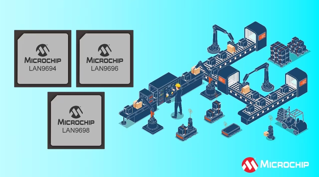
In a recent press release, Microchip Technology announced their new LAN969x series of chips powered by a powerful 1 GHz single-core Arm® Cortex®-A53 CPU. This new Ethernet switch offers scalable bandwidths, time-sensitive networking (TSN), and two redundancy protocols for increased reliability.
To be specific, the LAN969x series is made of three new chips: LAN9694 (46 Gbps), LAN9696 (66 Gbps), and LAN9698 (102 Gbps), each offering varying bandwidths for industrial applications. These chips are powered by a 1 GHz Arm Cortex-A53 CPU, known for its efficient performance. They support various Ethernet speeds, including 1 G, 2.5G, 5G, and 10G, and use the Arm Neon SIMD architecture, effective for vector processing.
Features of Microchip’s LAN969x Series Ethernet Switches:
LAN969x Series: Featuring the LAN9694, LAN9696, and LAN9698, designed specifically for industrial applications.
CPU: Equipped with a 1 GHz single-core Arm Cortex-A53 CPU, suitable for high-performance tasks in power-constrained environments.
Scalable Bandwidths: Ranging from 46 Gbps with the LAN9694, 66 Gbps with the LAN9696, to 102 Gbps with the LAN9698.
Protocols: Includes High-availability Seamless Redundancy (HSR) and Parallel Redundancy Protocol (PRP) for enhanced network reliability.
TSN Enabled: Assuring timely and deterministic communication for industrial automation.
Port Options: Up to 30 configurable Ethernet ports supporting interfaces like RGMII, SGMII, QSGMII, USGMII, and USXGMII.
QuadBox Functionality: Connects two HSR networks, providing high reliability and zero downtime in critical applications.
Security Features: Includes secure boot, secure firmware execution, TCAM-based frame processing, crypto libraries, and hardware security accelerators.
Ethernet Speed: Compatible with 1 G, 2.5 G, 5 G, and 10 G Ethernet speeds.
Development Support: Supported by EV23X71A Evaluation Board and IStaX VSC6817SDK Linux Application Software Package.
Applications: Targeting sectors like industrial automation, automotive, consumer, aerospace, defense, communications, and computing.
This device uses deterministic communication and time-sensitive networking (TSN) for reliability. TSN, per the IEEE 802.1Q standard, ensures timely Ethernet communication through scheduling. It involves end devices and bridge devices like LAN969x, using a central network controller to manage Ethernet frame transmission, and prioritizing TSN frames for time-critical tasks.
Microchip’s LAN969x Series Ethernet Switches can be purchased from Digikey where the LAN9698 sells for $81.16, the LAN9696 for $74.11, and the LAN9694 for $42.54.
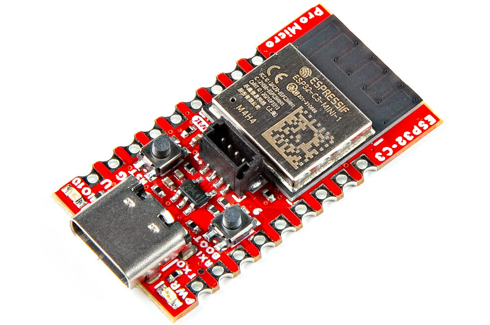
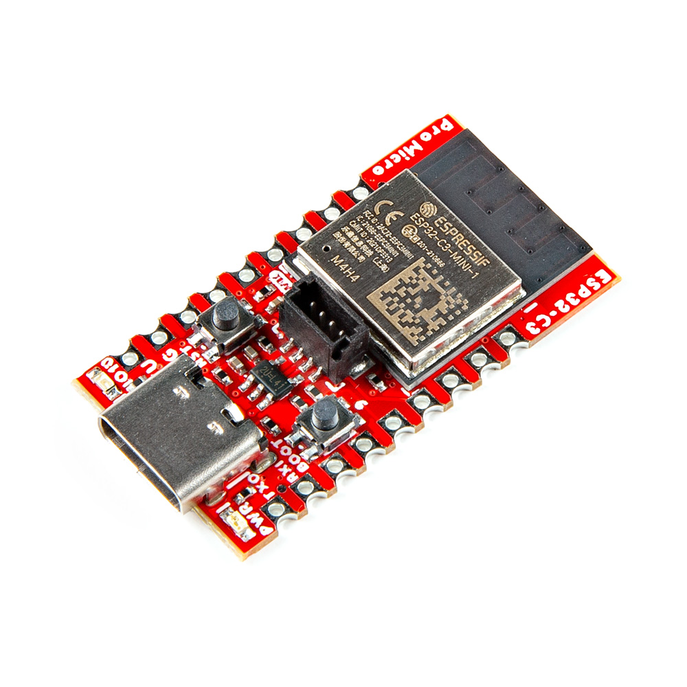
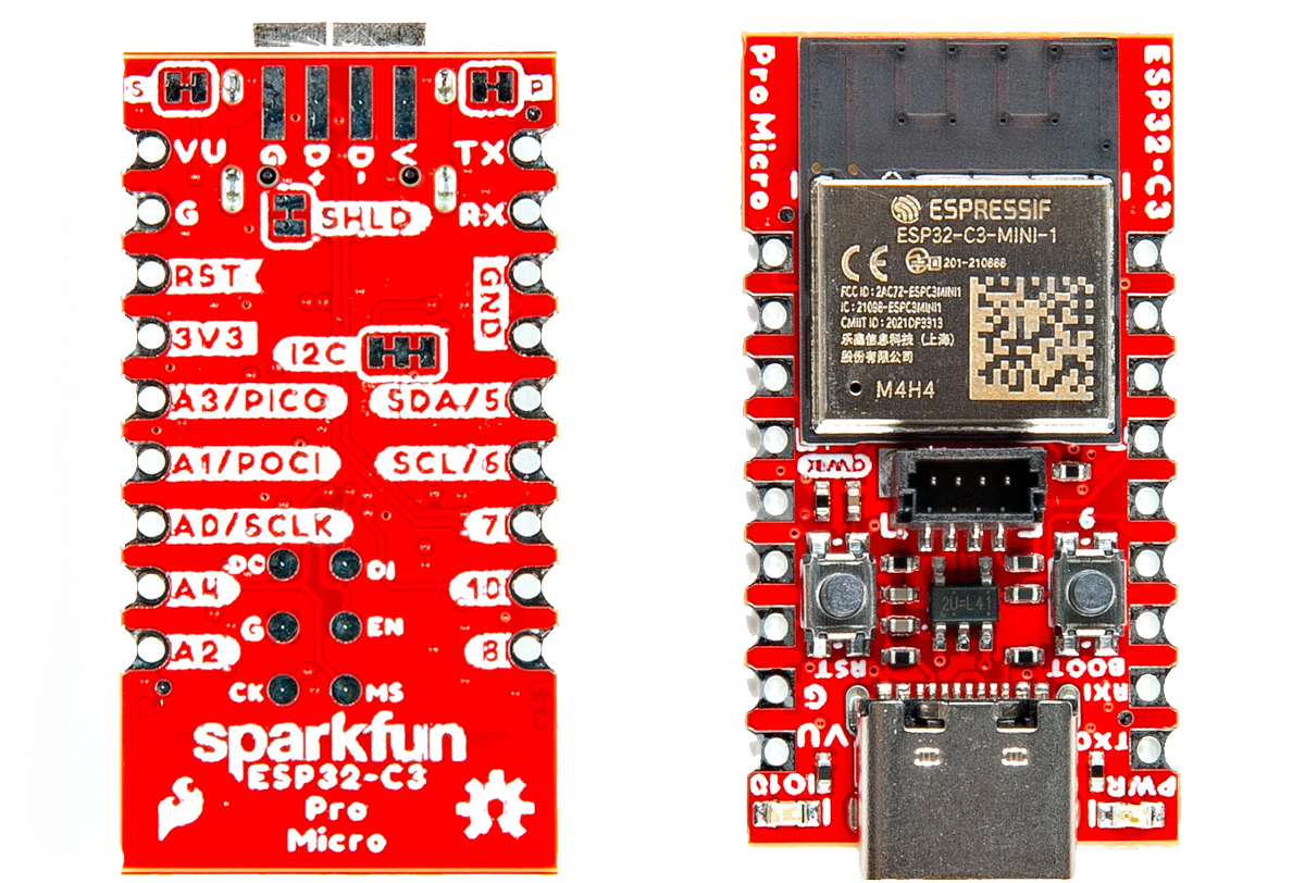
SparkFun has recently announced the “SparkFun Pro Micro – ESP32-C3” board, an ESP32-C3-based development board featuring SparkFun’s Qwiic Connect System. This compact board includes Wi-Fi, Bluetooth, GPIO, SPI, UART, I2C, I2S, and all the necessary hardware required for advanced IoT and embedded applications.
The Pro Micro ESP32-C3 features a RISC-V core, 400KB of SRAM, and runs at 160MHz, all integrated into a compact 1.3in. x 0.7in. board. It features an easy Qwiic connection, built-in WiFi, Bluetooth 5, and 22 GPIOs, supporting ADC, SPI, UART, and I2C, perfect for a wide range of projects.
SparkFun Pro Micro – ESP32-C3 Board Specifications:
CPU and On ChipMemory
ESP32-C3FH4 embedded,32-bit RISC-V single-core processor, up to 160MHz
384 KB ROM
400 KB SRAM (16 KB for cache)
8 KB SRAM in RTC
4 MB flash in a chip package
WiFi
802.11b/g/n
Center frequency range of operating channel:2412~2484 MHz
Supports 20 MHz, 40 MHz bandwidth in 2.4 GHz band
1T1R mode with data rate up to 150 Mbps
Wi-Fi Multimedia (WMM)
TX/RX A-MPDU, TX/RX A-MSDU
Immediate Block ACK
Fragmentation and defragmentation
Bluetooth
Bluetooth LE: Bluetooth 5, Bluetooth mesh
Speed: 125 Kbps, 500 Kbps, 1 Mbps, 2 Mbps
Channel selection algorithm #2
Internal co-existence mechanism between Wi-Fiand Bluetooth to share the same antenna
Peripherals
GPIO, SPI, UART, I2C, I2S, remote control peripheral, LED PWM controller, general DMA controller, TWAI®controller (compatible with ISO11898-1, i.e. CAN Specification 2.0), USBSerial/JTAG controller, temperature sensor, SARADC, general-purpose timers, watchdog timers
Integrated Components on Module
40 MHz crystal oscillator
Antenna Options
On-board PCB antenna (ESP32-C3-MINI-1)
Operating Conditions
Operating voltage/Power supply: 3.0 ~ 3.6 V
Operating ambient temperature: –40 ~ 85 °C
1x Vertical Qwiic Connector
The SparkFun Pro Micro ESP32-C3 supports Espressif’s ESP-IDF and Arduino IDE, offering a wealth of libraries and community support for diverse projects. Ideal for wearables, and IoT devices.
For the Pro Micro ESP32-C3, SparkFun offers resources, all accessible through their GitHub repository. This includes the schematic, Eagle files, board dimensions, a hookup guide, the ESP32-C3FN4 datasheet, a reference manual, information on the Qwiic system, and much more.
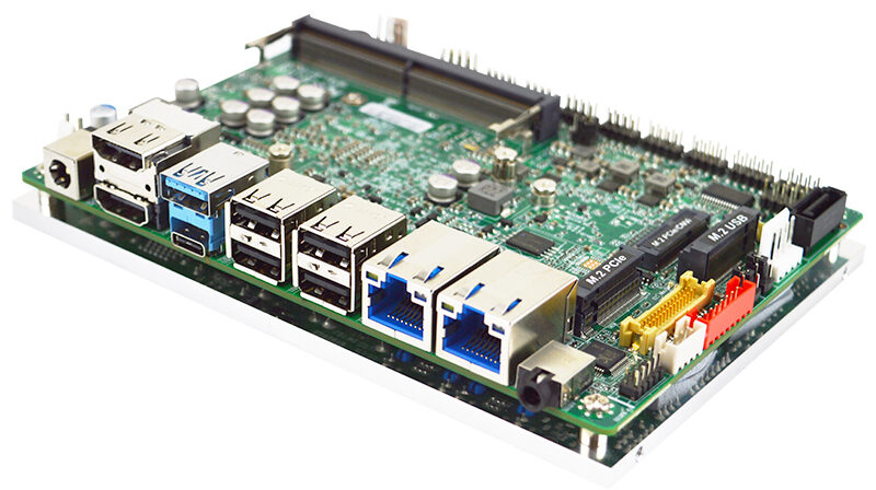
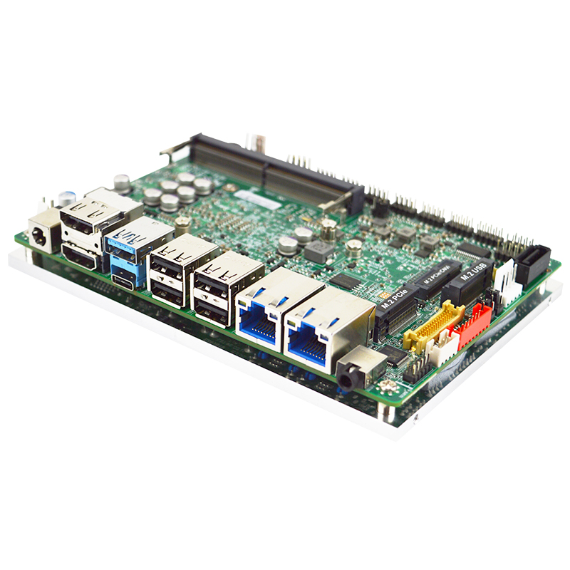
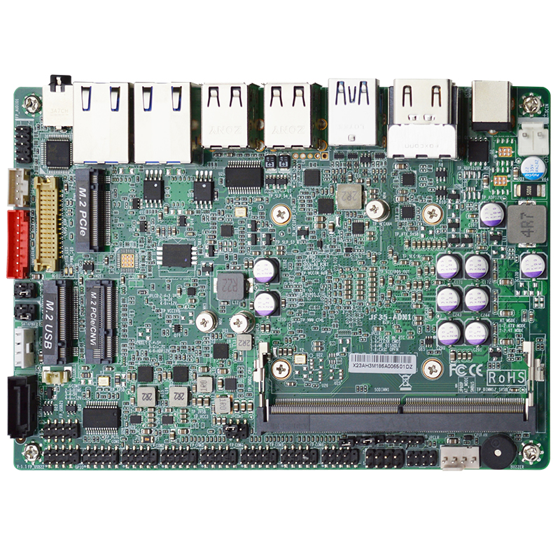
Jetway has launched a new 3.5-inch board named Jetway F35-ADN1, featuring the Intel N97 processor. It supports up to 32GB DDR5 memory, has options for HDMI and DP for display, and includes dual Ethernet ports for network connections. The board is certified with CE/FCC Class A certifications, making it an optimal choice for applications in industrial robotics, payment systems, and machine vision.
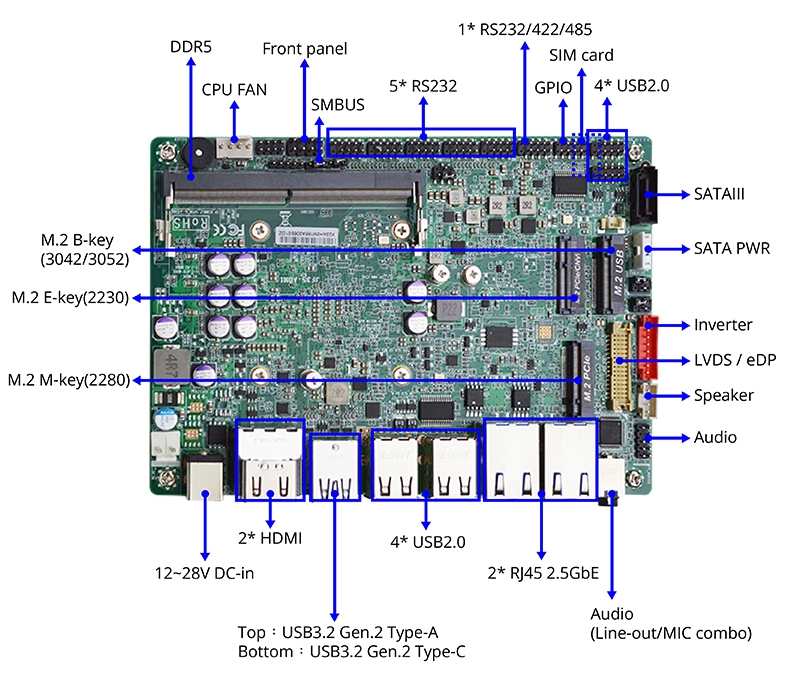
The Jetway JF35-ADN1 includes two 2.5GbE ports, eight USB 2.0 ports, two USB 3.2 Gen 2 ports, supports up to 32GB DDR5 RAM, and can power three displays with two HDMI 2.0b and one DisplayPort over USB-C.
Jetway F35-ADN1 Motherboard Specifications:
CPU: Onboard Intel N97 Processor (Alder Lake N)
CPU TDP: 12W
Chipset: Integrated with Intel® SoC
Memory Type: 1 x DDR5 4800MHz, Single Channel SODIMM up to 32GB
BIOS: UEFI
Wake on LAN: Yes
Watchdog Timer: 255 Levels
Security: TPM2.0 (Optional)
RTC Battery: Lithium Battery 3V/220mAh
Dimension (L x W): 148mm x 102mm (5.8″ x 4″)
OS Support: Windows 10 (64bit), Windows 11 (64bit), Linux, TBC
Form Factor: 3.5″ SBC
Power:
Power Requirement: +12~28V
Power Supply Type: AT/ATX
Connector: 2-pin Header
Display:
Controller: Intel® UHD Graphics
LVDS/eDP/MIPI-DSI: 1 x LVDS, up to 1920×1200@60Hz (support 12V/2A panel) (optional eDP)
Display Interface:
2 x HDMI 2.0b, up to 4096×2160@60Hz
1 x DP 1.4a, up to 4096×2304@60Hz (from external USB Type C)
Multiple Display: Support for 3 Displays
Audio:
Codec: Realtek ALC897
Audio Interface: 1 x external Line-out/MIC combo
Speaker: 1 x internal speaker
External I/O:
Ethernet: 2 x Intel® i225-V, 10/100/2500Base
USB:
1 x USB3.2 Gen 2 Type C (ALT mode)
1 x USB3.2 Gen 2
4 x USB2.0
Video:
2 x HDMI 2.0b
1 x DP 1.4a (from external USB Type C)
Internal & Internal I/O:
Ethernet: 2 x Intel® i225-V, 10/100/2500Base
USB: 4 x USB2.0
Serial Port:
1 x RS232/422/485 (COM 1 support 5V/12V)
5 x RS232
Front Panel:
HDD LED
PWR LED
Power Button
Reset
Others:
1 x Chassis intrusion
1 x AT mode
Video: 1 x LVDS (optional eDP)
Audio: 1 x Audio Header, 3W amplifier
GPIO: 8-Bit
SMBUS: Yes
Fan: 1 x CPU Smart Fan
SIM: Nano
Storage:
SATA: 1 x SATA3, 1 x SATA Power Connector
M.2: 1 x M-Key 2280 (PCIe 3.0 x2) support NVMe
eMMC: Onboard 64GB eMMC 5.1 (optional)
M.2 Expansion:
1 x E-Key 2230 (USB2.0/PCIe 3.0 x1) support CNVi
1 x B-key 3042/3052 (USB3.1/USB2.0) support 4G/5G module
Environment & Certification:
Operating Temperature: 0°C ~ 60°C (32°F ~ 140°F)
Storage Temperature: -20°C ~ 85°C (-4°F ~ 185°F)
Operating Humidity: 10% ~ 90% RH, non-condensing
Certification: Meet CE/FCC Class A
Packing List:
JF35-ADN1 MB: 1
Flat type Heatsink (HCS3XXMHT03S-5F): 1 (assembled)
CPU plate (HCS376MHT01S-F): 1 (assembled)
SATA cable (G01-SATA3-BL-1F), 50cm: 1
SATA Power Y cable (G01-PW4PS2S-322-1F), 5.0pitch for 32cm, 2.54pitch for 20cm: 1
COM Port Cable (G01-COM-H2M22-1), 22cm, Pitch 2.0: 1
The board is designed for Automated Guided Vehicles (AGV) and is adaptable for uses like machine vision and payment systems. It’s an entry-level solution for industrial robotics, compared to the more advanced UP Xtreme 7100.
The Jetway F35-ADN1 single-board computer (SBC) is now available and being mass-produced. For more information, including documentation and software drivers, visit the product page.
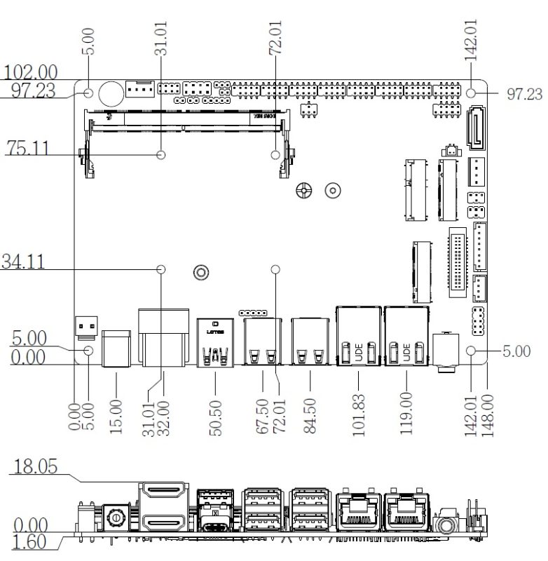
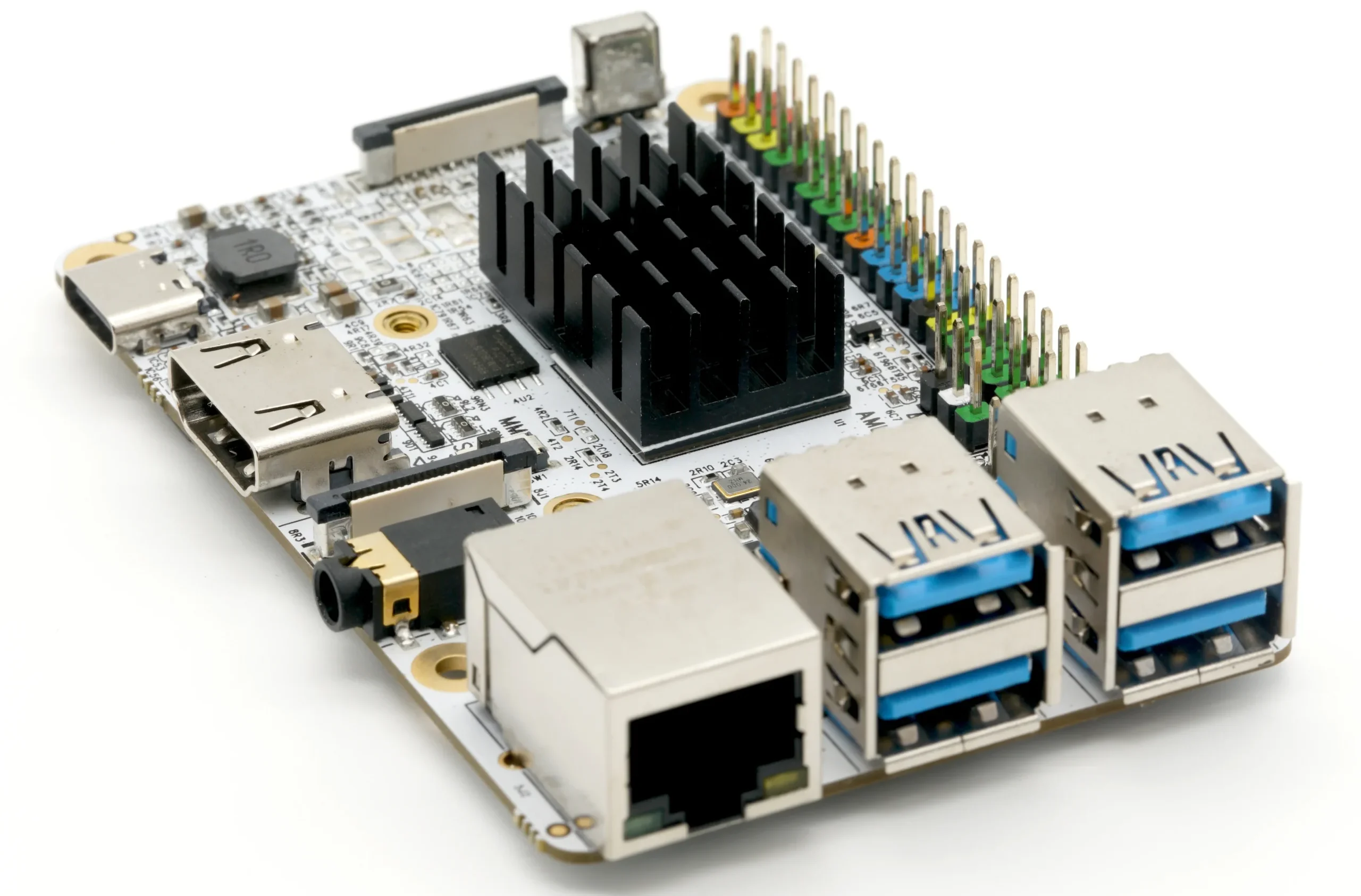
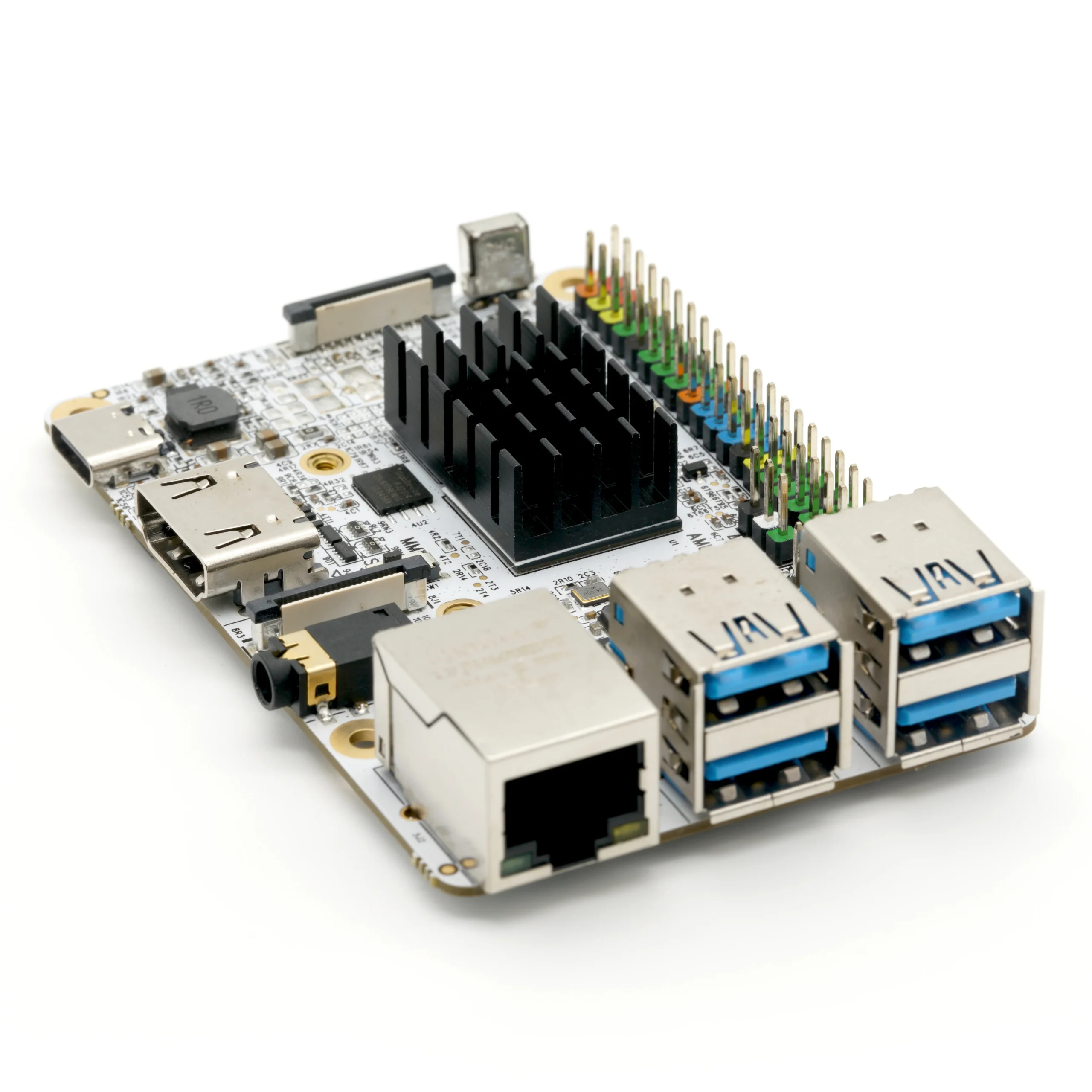
Libre Computer just announced their latest and greatest product the Solitude AML-S905D3-CC. It’s a $45 SBC powered by the Amlogic S905D3 processor and has support for UEFI Bios and standard Linux distributions.
The AML-S905D3-CC uses the Amlogic S905D3, it is a CPU based on the ARM Cortex-A55 architecture and features 4 efficient cores for computing and 2 cores for graphics processing. It also includes over 1 TOPS of NPU cores specifically designed for AI tasks.
The Libre Computer Solitude board offers 2-4GB LPDDR4X memory, eMMC and MicroSD storage, HDMI 2.1, and a 3.5mm audio jack. It supports 1080P displays and camera modules, has Gigabit Ethernet for high-speed network access, four USB 3.0 ports, Power over Ethernet(PoE), and a 40-pin GPIO header compatible with Raspberry Pi and CC ecosystems.
Key Specification of Libre Computer Solitude AML-S905D3-CC SBC:
Processor:
4 E Cores
2 E GPU Cores
1+1 NPU Cores
Memory and Storage:
RAM: 2GB/4GB LPDDR4
Flash Storage: 16MB SPI NOR
eMMC: 5.x Slim Connector
MicroSD: Card Slot with UHS SDR104
Display and Multimedia:
HDMI: HDMI 2.0
Display Interface: DSI 4-Lane on 22-Pin Connector
Audio: CVBS with Analog Stereo Audio 3.5mm Jack
Connectivity:
Ethernet: Gigabit Ethernet
USB Ports:
4 USB Type-A 3.0 (Hub)
USB Type C Power and 2.0 Data (Dual Role)
GPIO: 40-pin GPIO Connector
Other Interfaces:
IR Receiver Sensor
CSI 2-Lane on 22-Pin Connector
Power:
PoE Connector: Yes
Libre Computer mentions that the Solitude single-board computer (SBC) smoothly transitions hardware for CC form factor applications, using the features of the Cottonwood platform. It can also start up with any standard Libre Computer software due to its BIOS, which simplifies hardware details via UEFI.
The Libre Computer Solitude, featuring 4GB of RAM, is currently available for purchase for $45. However, it’s worth noting that the more budget-friendly 2GB RAM variant of the Solitude is currently unavailable, as it appears to be out of stock at the moment.
Arduino and Silicon Labs are teaming up to make it easier to use the Matter protocol for IoT devices. This project will happen in two phases. The first phase, which took place at CES 2024, involved the release of a user-friendly Arduino library for the Matter protocol, along with a new core for SiLabs microcontrollers. In the second phase, they plan to launch a new Arduino board based on the SiLabs MGM240SD22VNA microcontroller on Arduino Day, in March 2024.
The MGM240SD22VNA Series 2 wireless module is designed for IoT devices using Matter, Thread, Zigbee, and Bluetooth. It features an ARM Cortex-M33 with 10 dBm power output power, low energy use, AI/ML acceleration, top-level security, and lots of memory and GPIOs for robust, efficient, and secure applications.
Matter is an open-source royalty-free connectivity standard developed by the Connectivity Standards Alliance (CSA), formerly known as the Zigbee Alliance. This alliance includes companies like Apple, Google, Amazon, and Silicon Labs among other members. Together they want to increase compatibility among smart home products and improve the reliability of these devices.
As I mentioned earlier, the company is set to release a new Arduino Nano Board with SiLabs MGM240SD22VNA in March 2024. Just like the Sparkfun board, this will be the first Arduino board with a Silicon Labs microcontroller that works with the Matter Protocol. The new Arduino Core for Silicon Labs devices, along with this Arduino Nano, will make it easier to experiment with Matter and other wireless technologies for smart homes.
This summarizes all the information provided by the company. Additional details can be found on the announcement page.
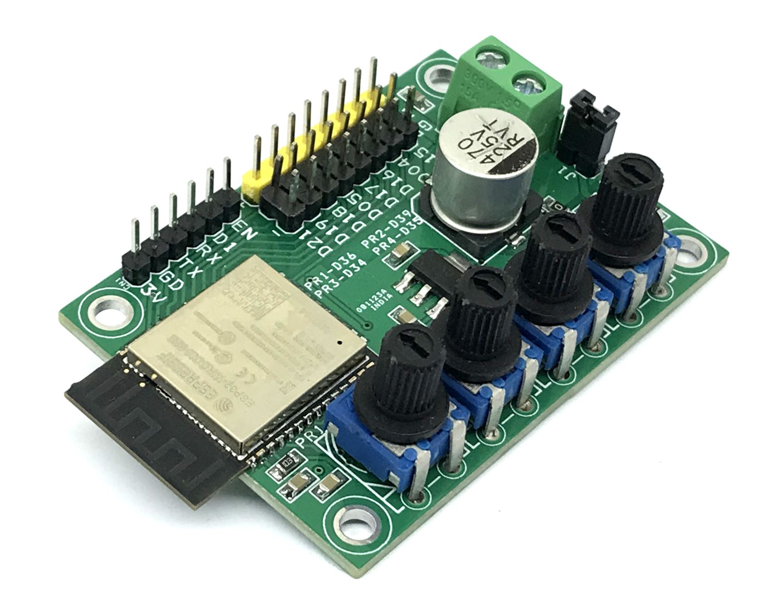
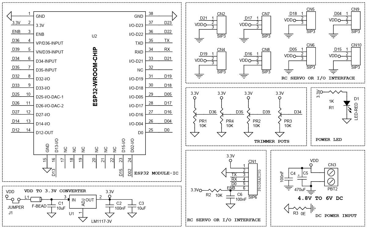
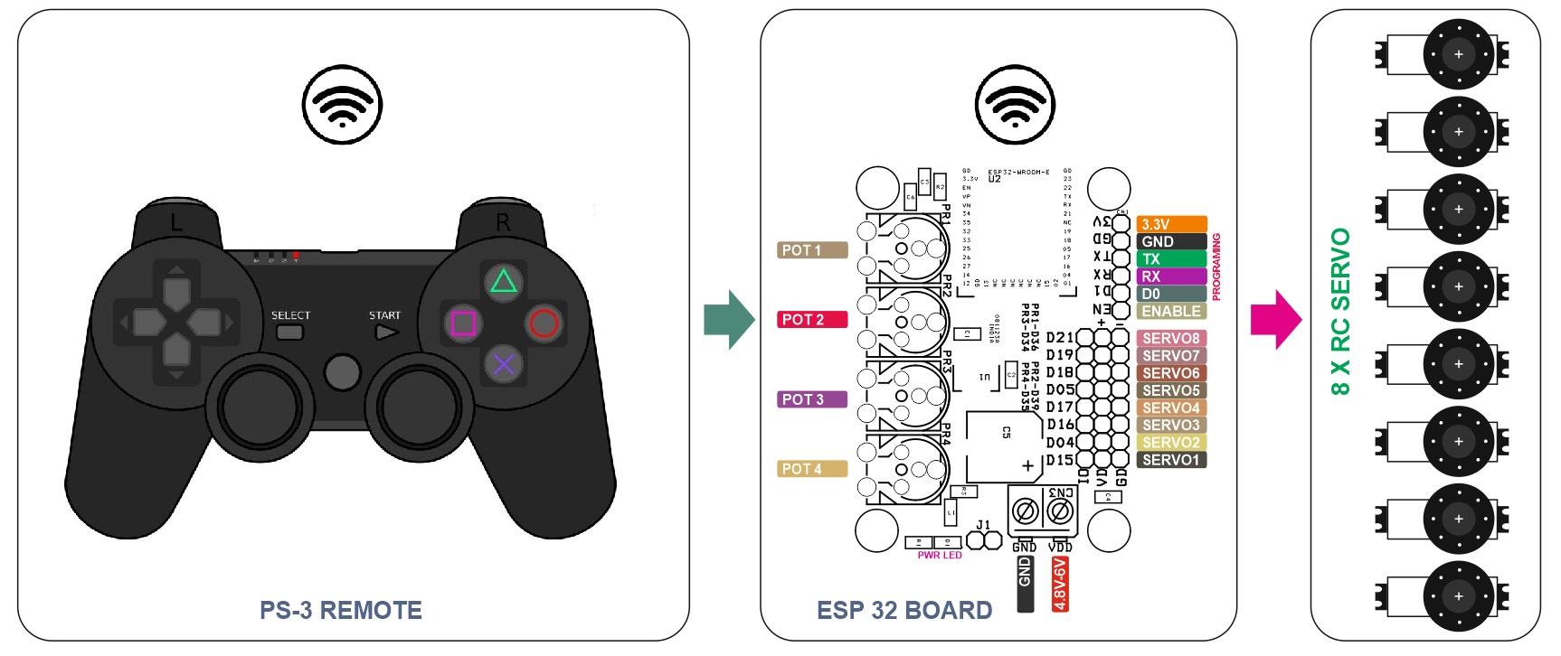
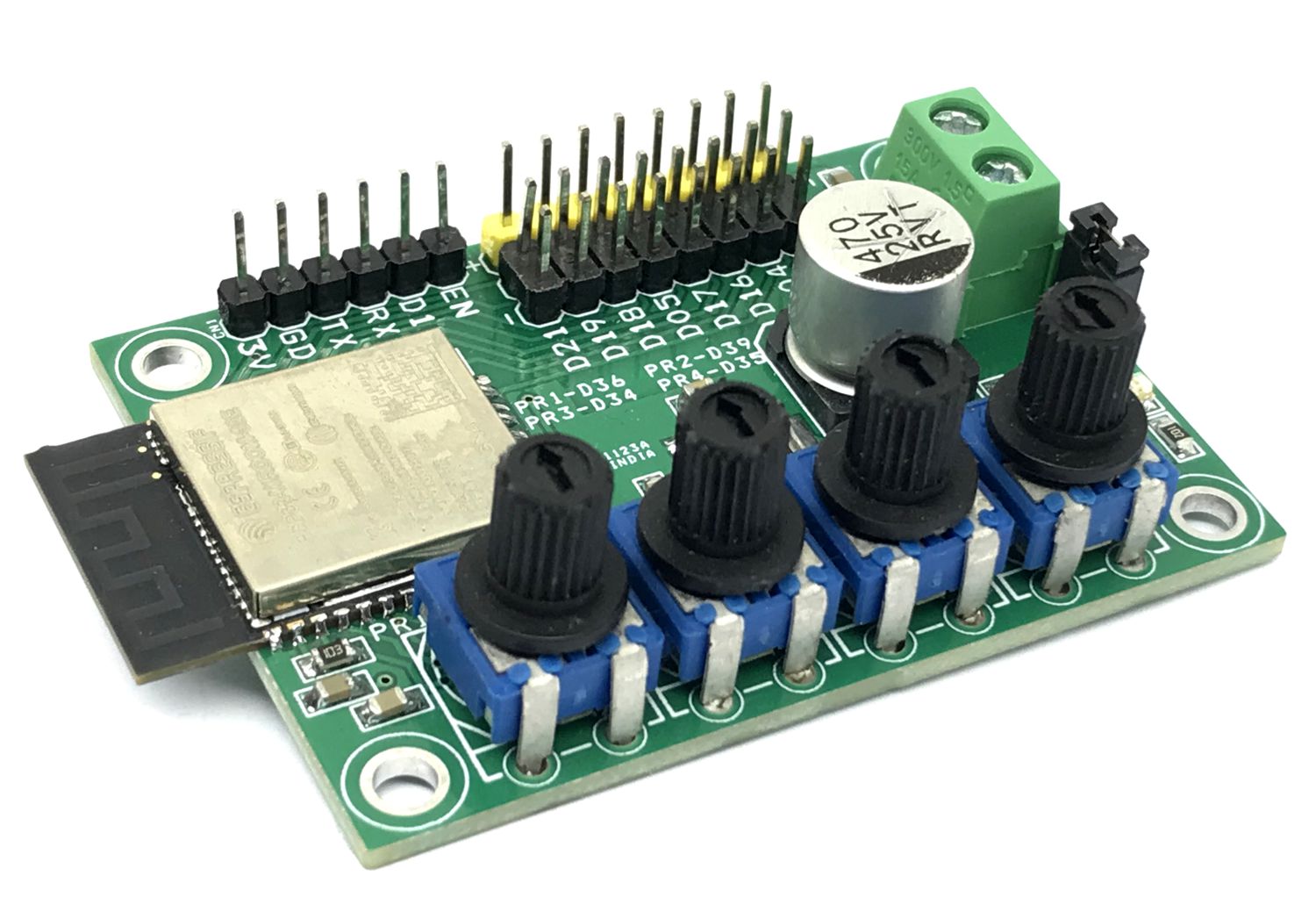
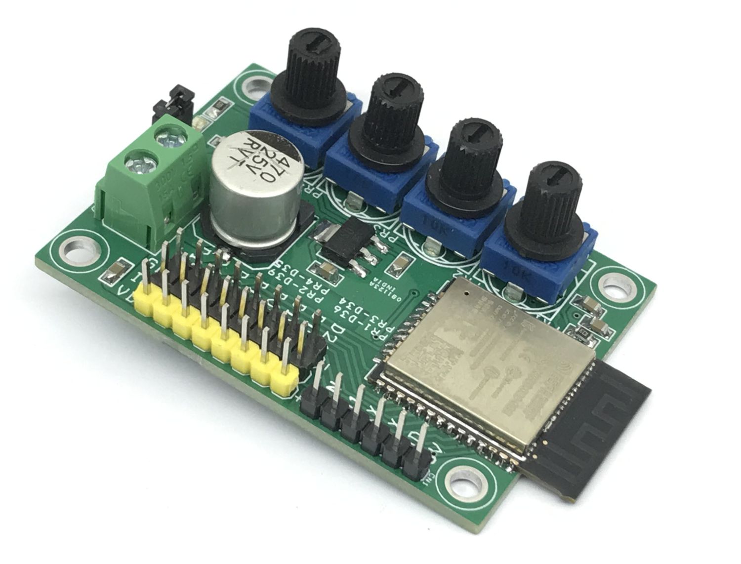
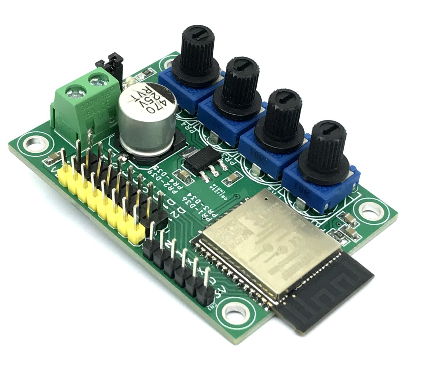
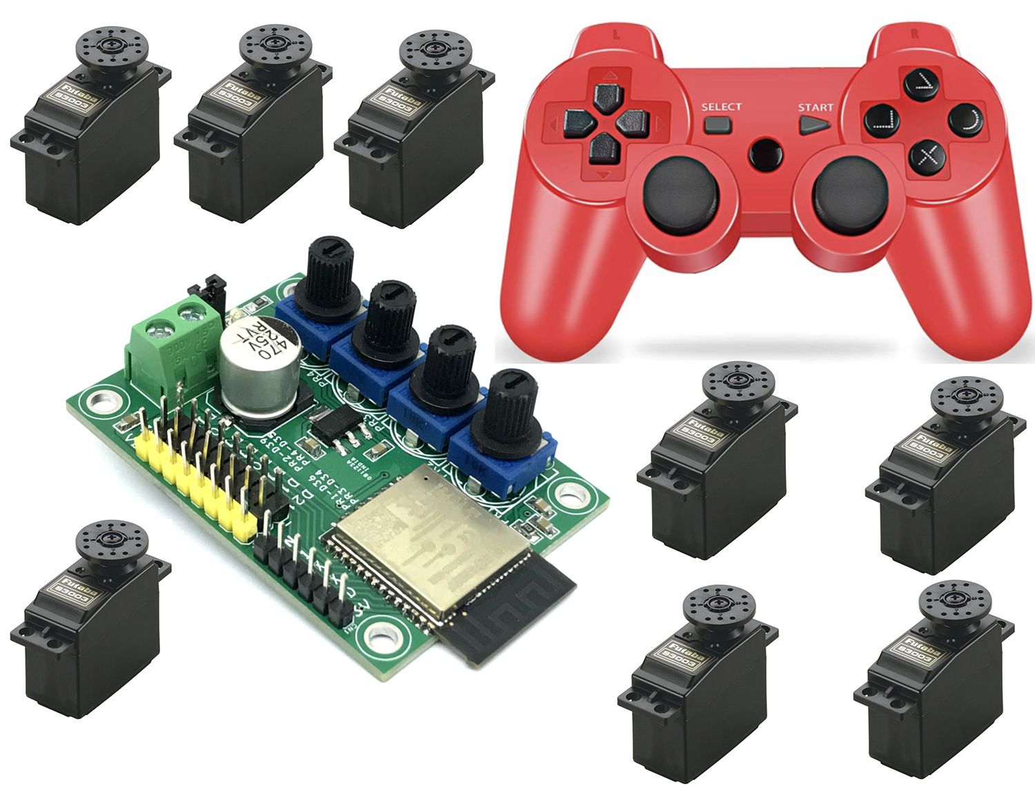
This project enables the user to control an RC servo-based robotics arm wirelessly. The board is based on ESP32-WROOM32E Bluetooth/Wi-Fi module, thus PS3 or PS4 wireless remote can be paired. The project is built using ESP32 chip with Bluetooth and Wi-Fi connectivity, 4 potentiometers connected to analog pins, 8 x 3 pin header connectors for easy interface of RC servos, operating power supply range 4.8V to 6V DC, LM1117-3.3V U1 regulator provides 3.3V to ESP32 processor, DC supply capacitor C5 helps smooth operations of RC servos, use a shunt to close the jumper J1.
ESP32 can be programmed using ARDUNO IDE. Example code provided to test the project. The user will be able to drive one RC Servo connected to the GPIO15 pin of ESP32. Use the right-hand side joystick of PS3 to perform movement of the RC Servo. more details about the ESP32 and PS3 interface are available here:
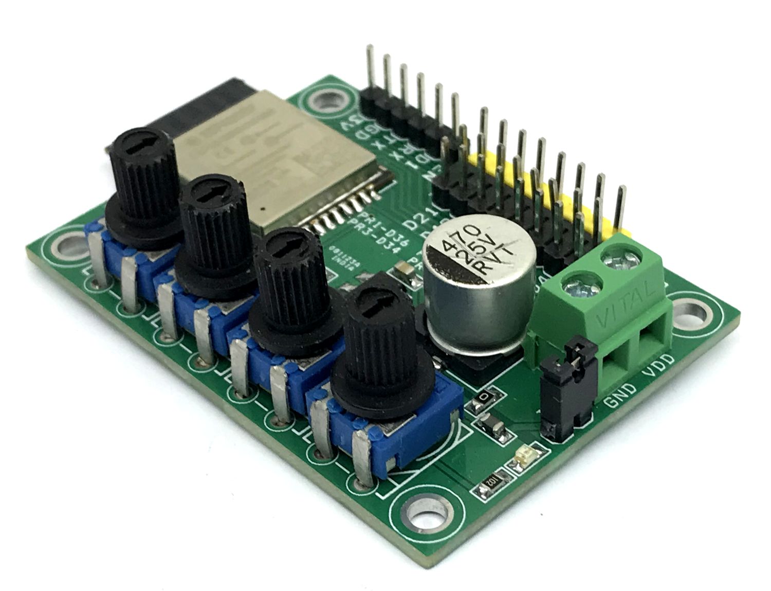
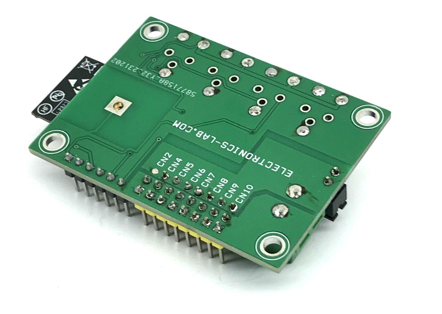
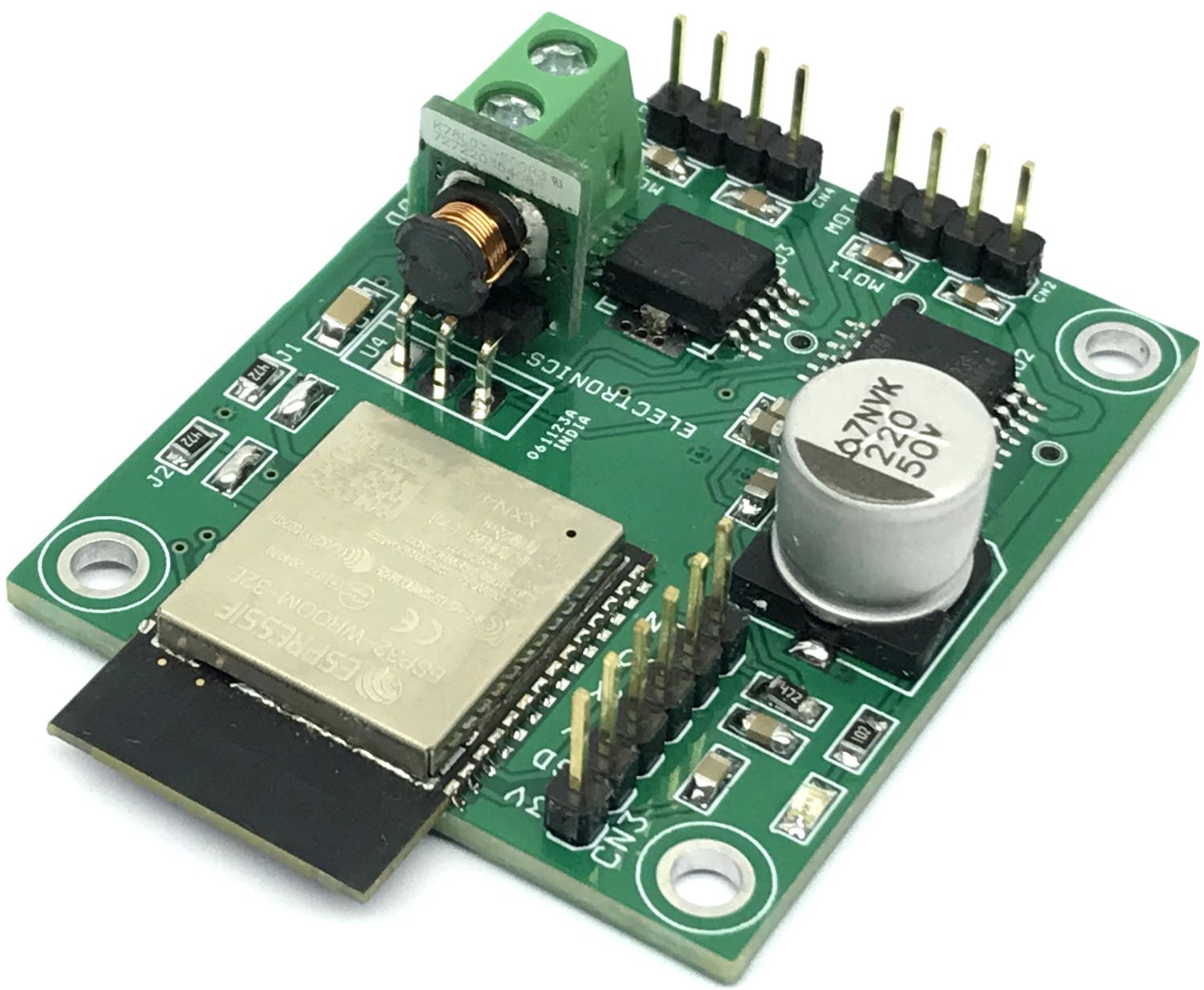
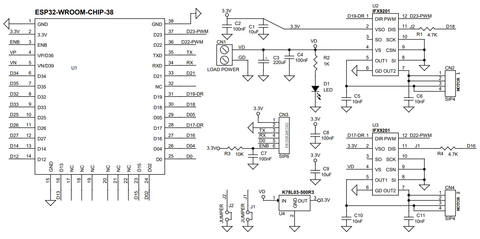
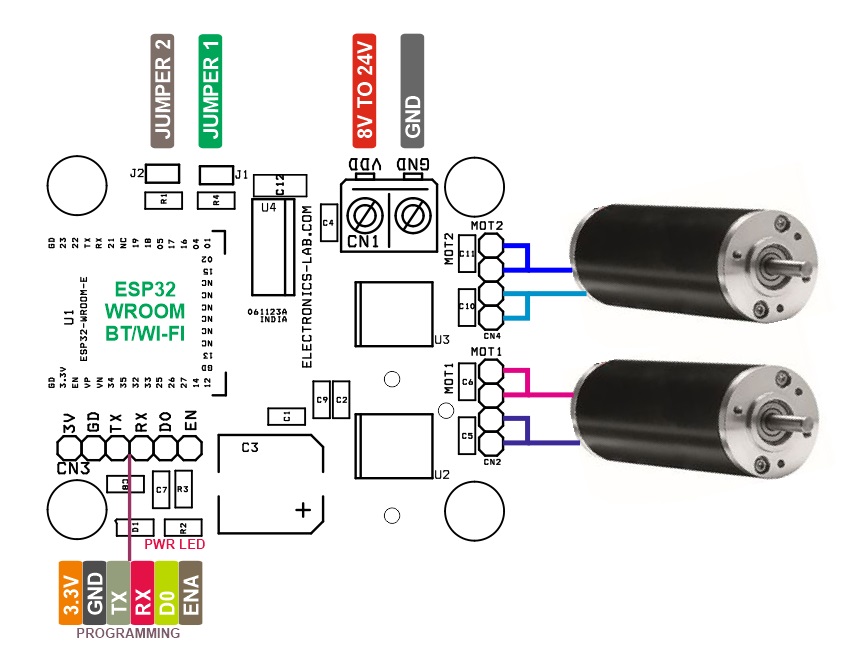
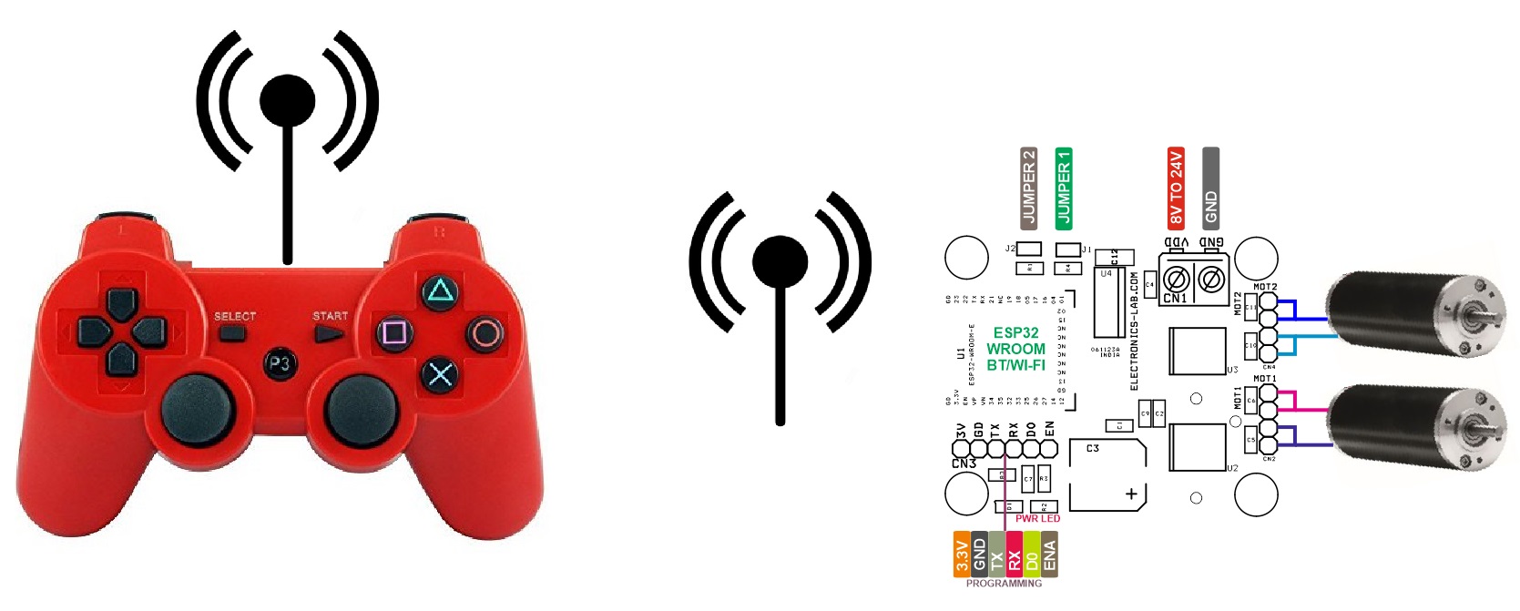
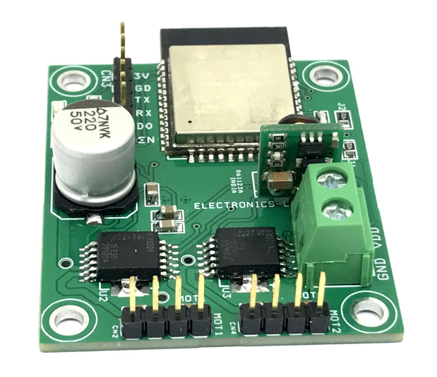
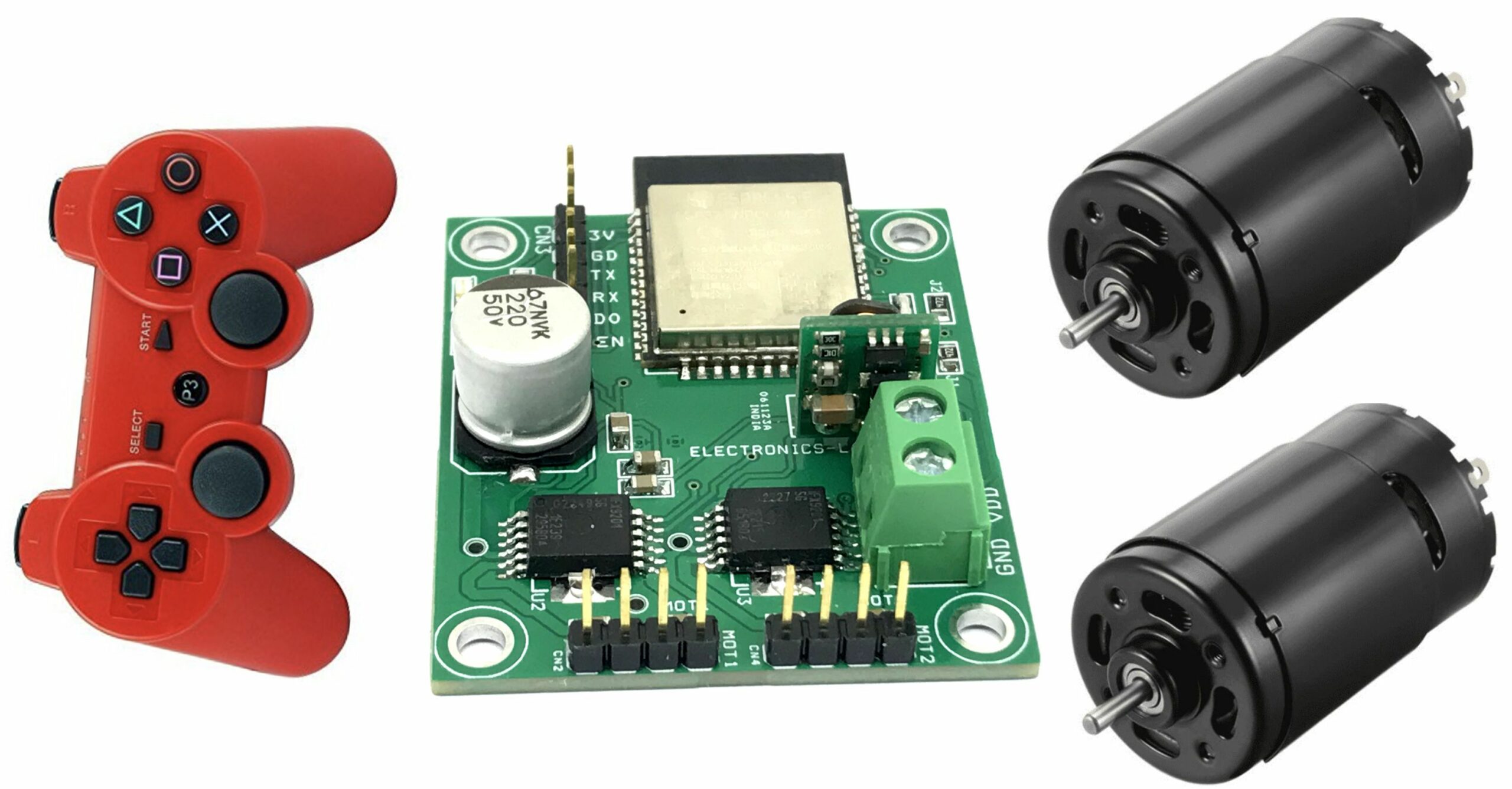
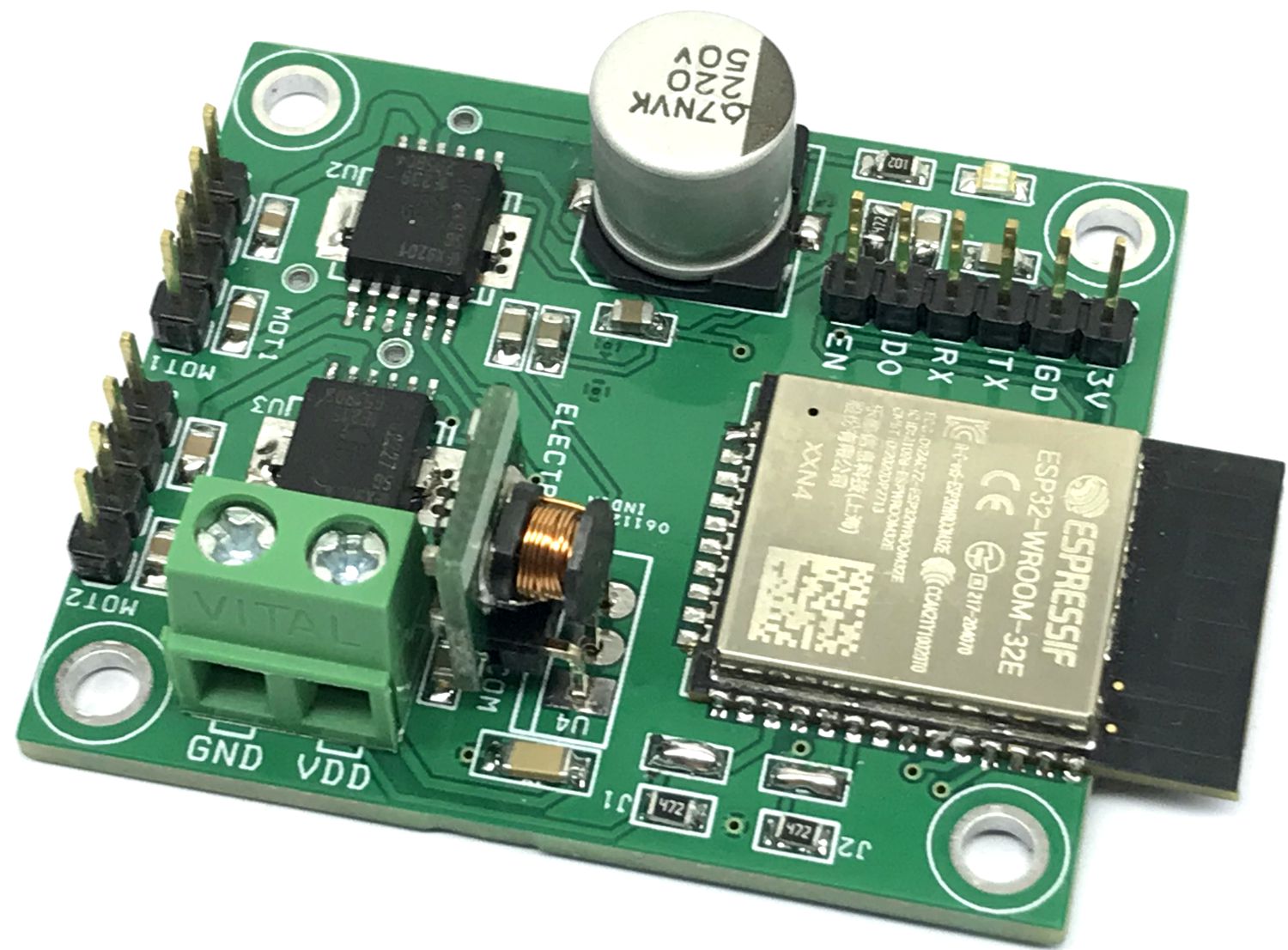
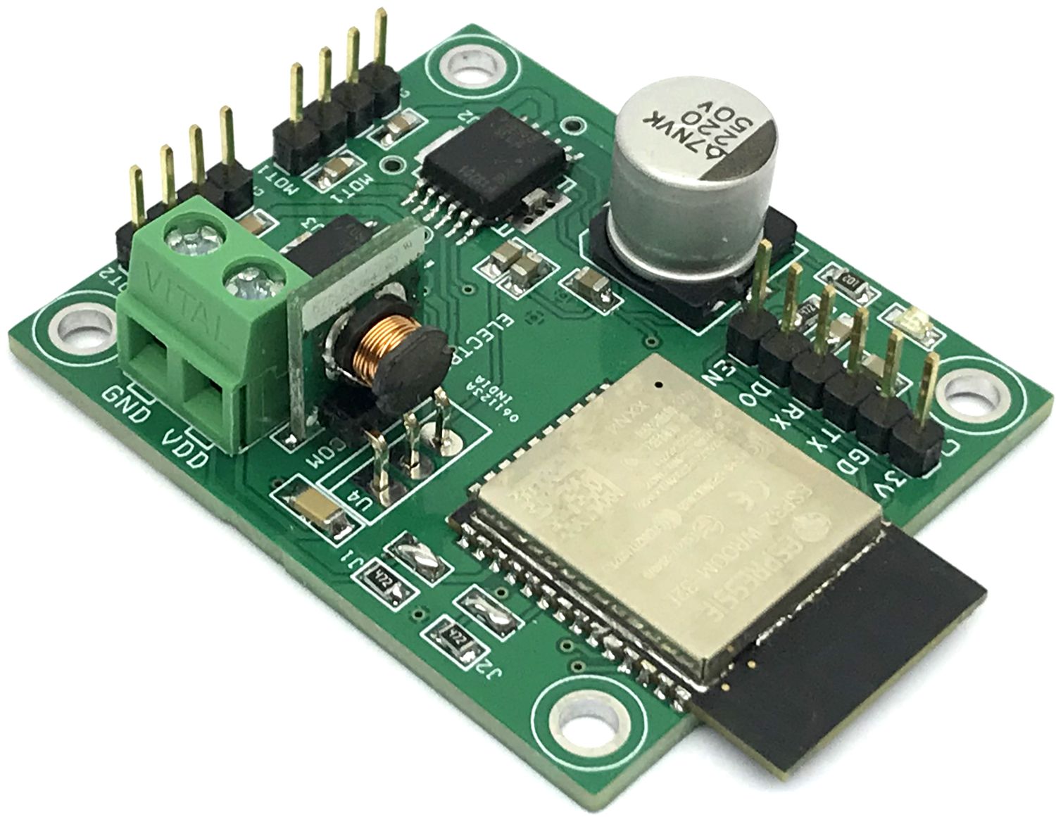
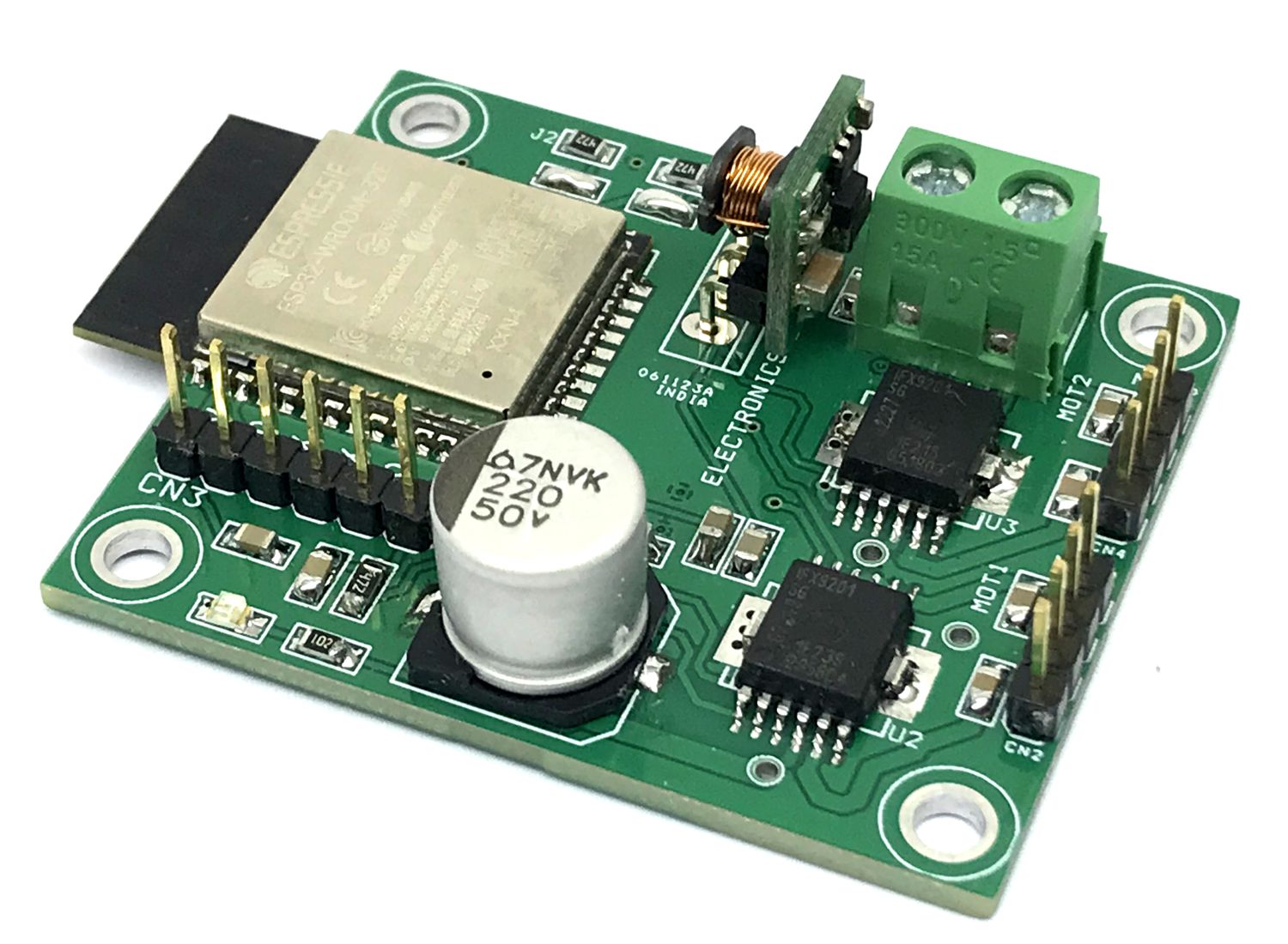
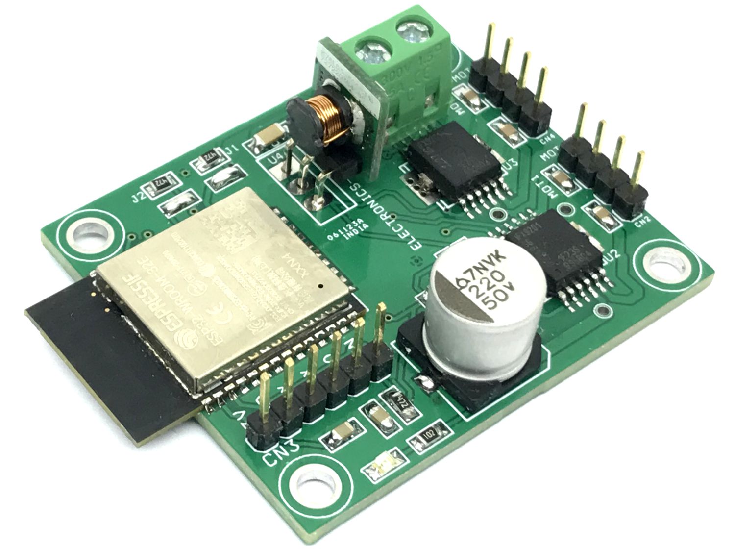
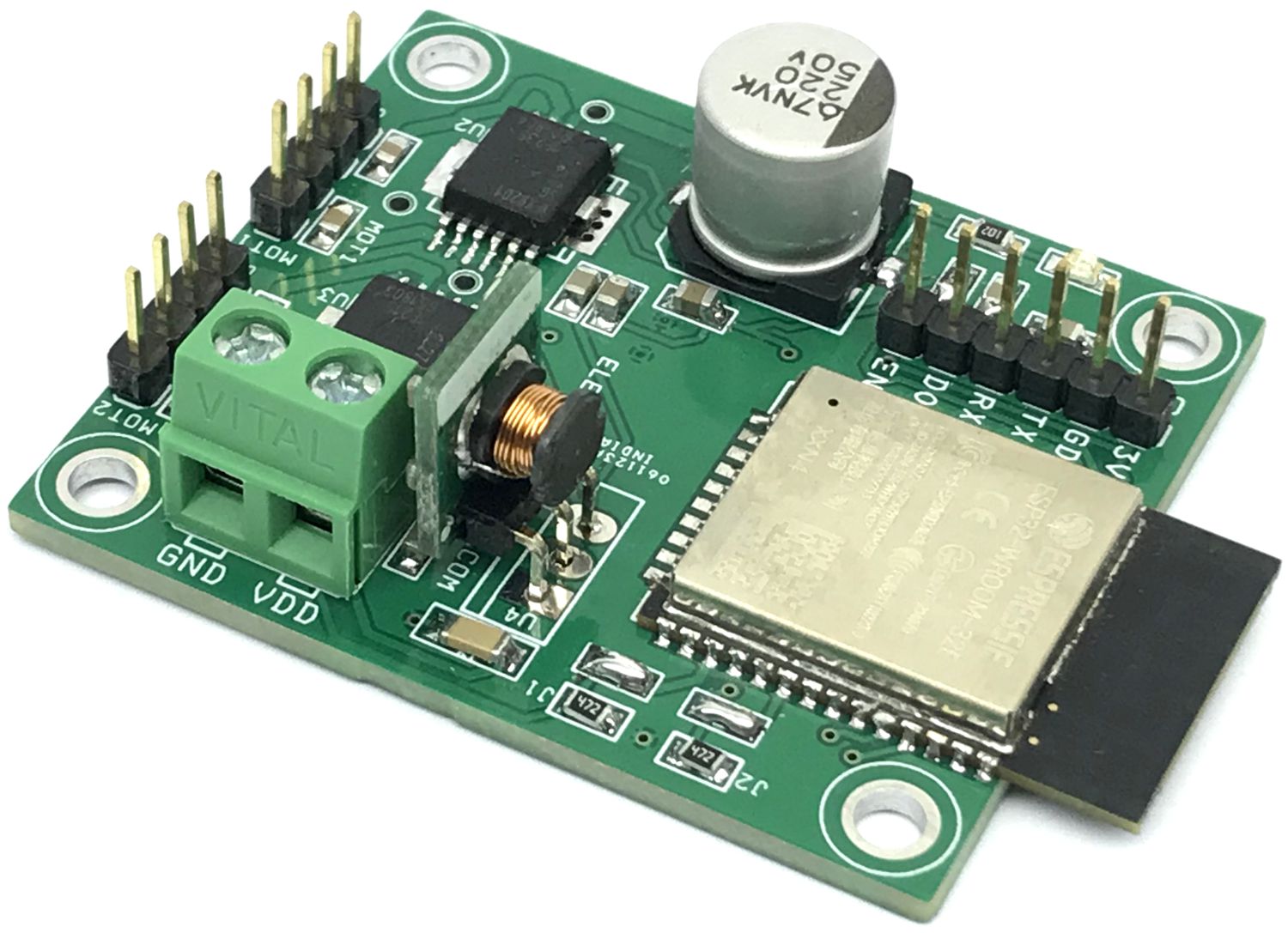
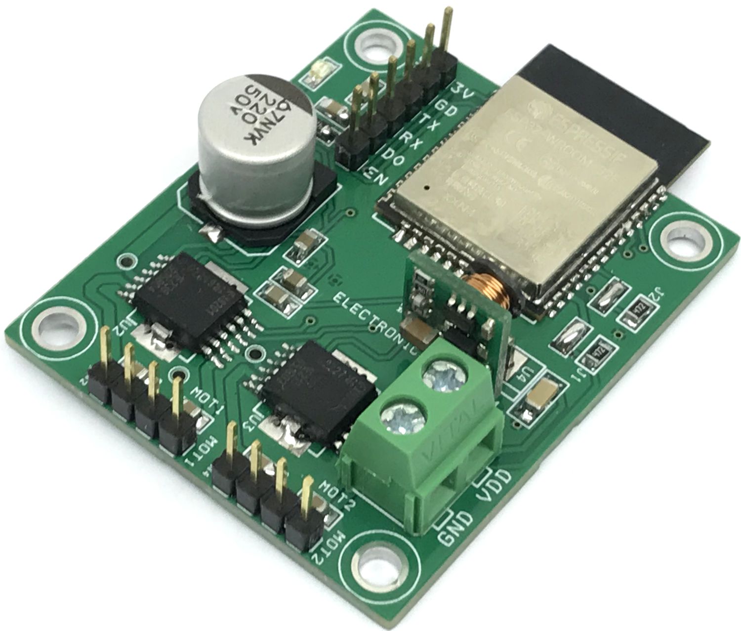
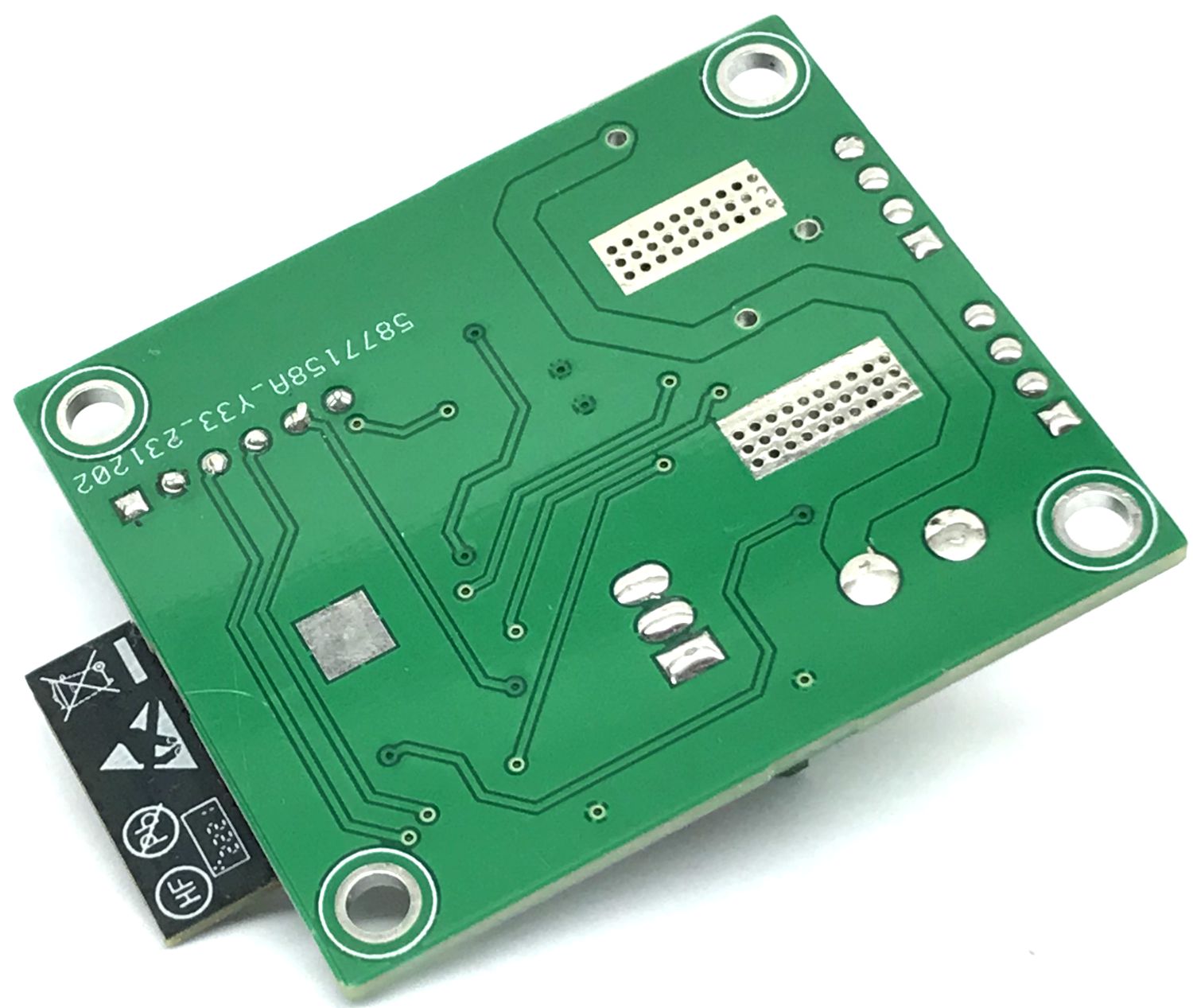
This wireless robot car controller board is built using an ESP32 BT/Wi-Fi module, 2 x H-Bridges, 3.3V regulator. It also includes an ESP32 programming connector, power LED, screw terminal connector for the power supply, header connector for motors, and high-value capacitors on the DC supply for smooth motor operations. The operating power supply is 8V to 24V DC. The project has two H-brides and each can drive 2.5A continues. The board is suitable for small and medium-sized robot cars. It is an open-source hardware project that can be programmed as per requirement. ESP32 I/O details are available in descriptions. ESP32 supports Bluetooth connectivity and the robot car can be controlled using a small phone, Laptop, or Tablet. The project was built using an ESP32-Wroom processor and this chip supports Bluetooth and Wi-Fi connectivity.
The project can be tested with example Arduino code which is provided below. The user will be able to drive a robot car with a PS3 Bluetooth remote. Refer to the link below to learn more about PS3 and ESP32 pairing, and ESP32 programming under Arduino IDE.
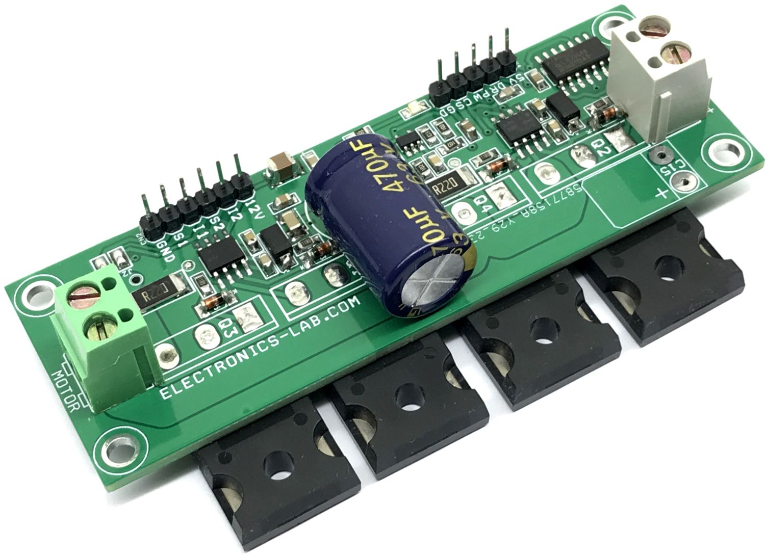
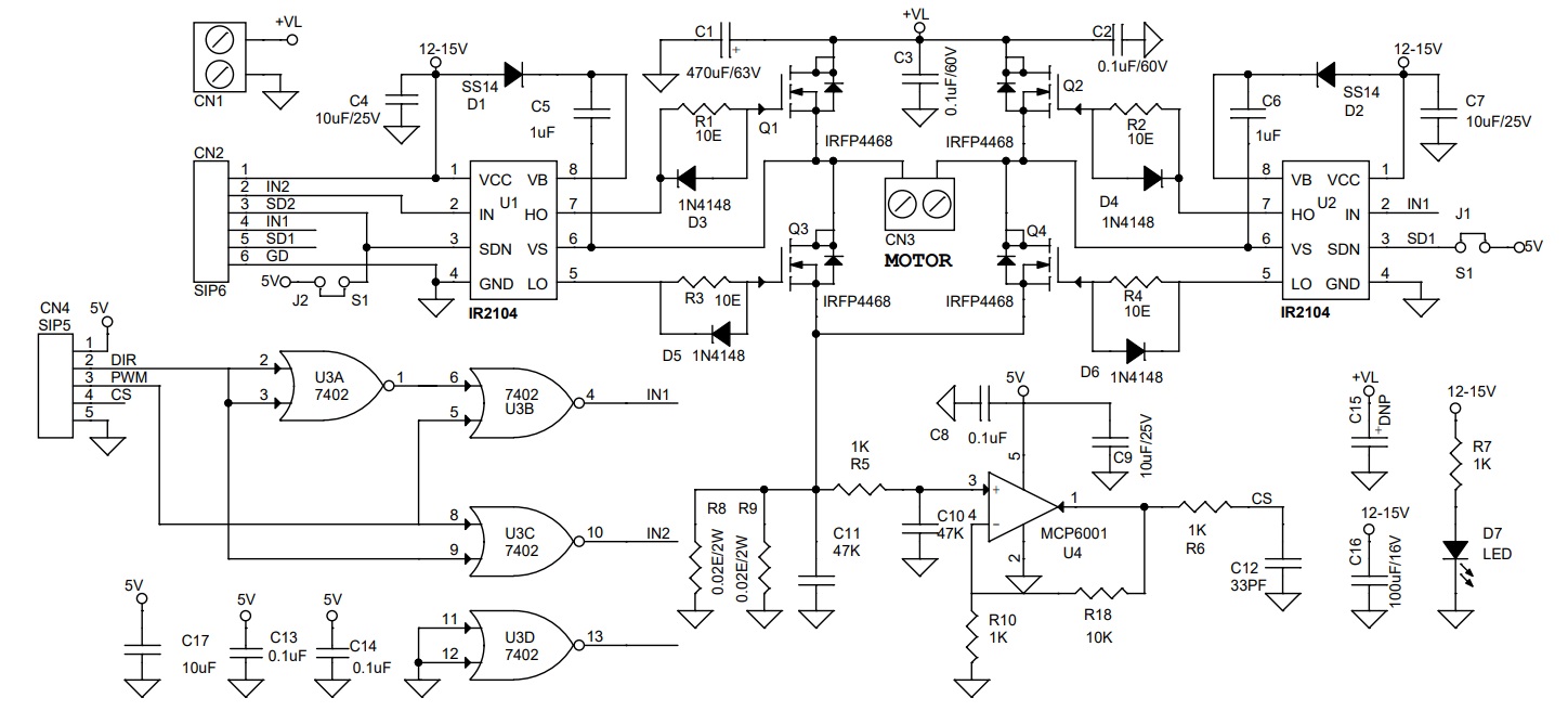
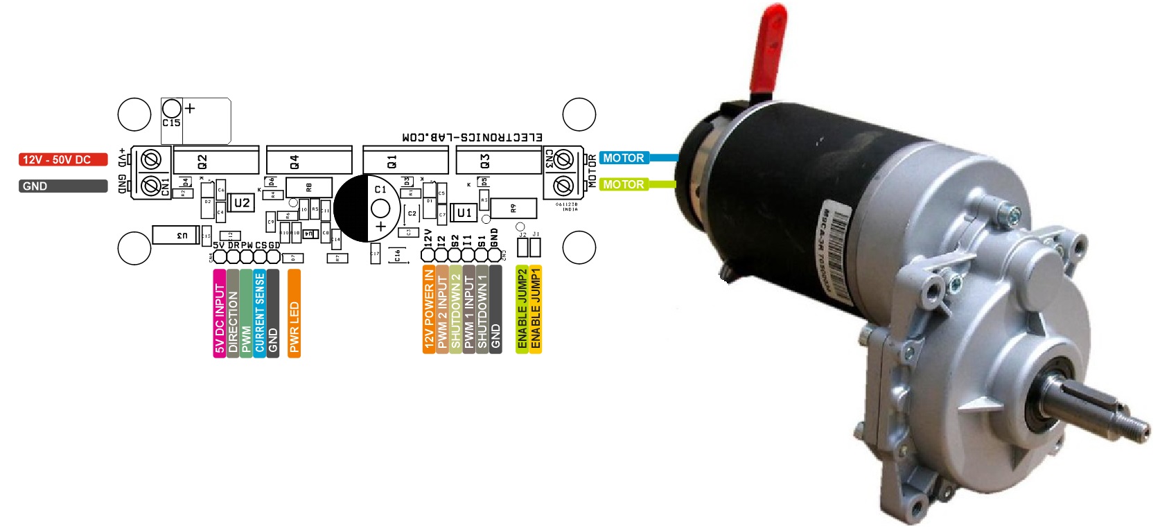
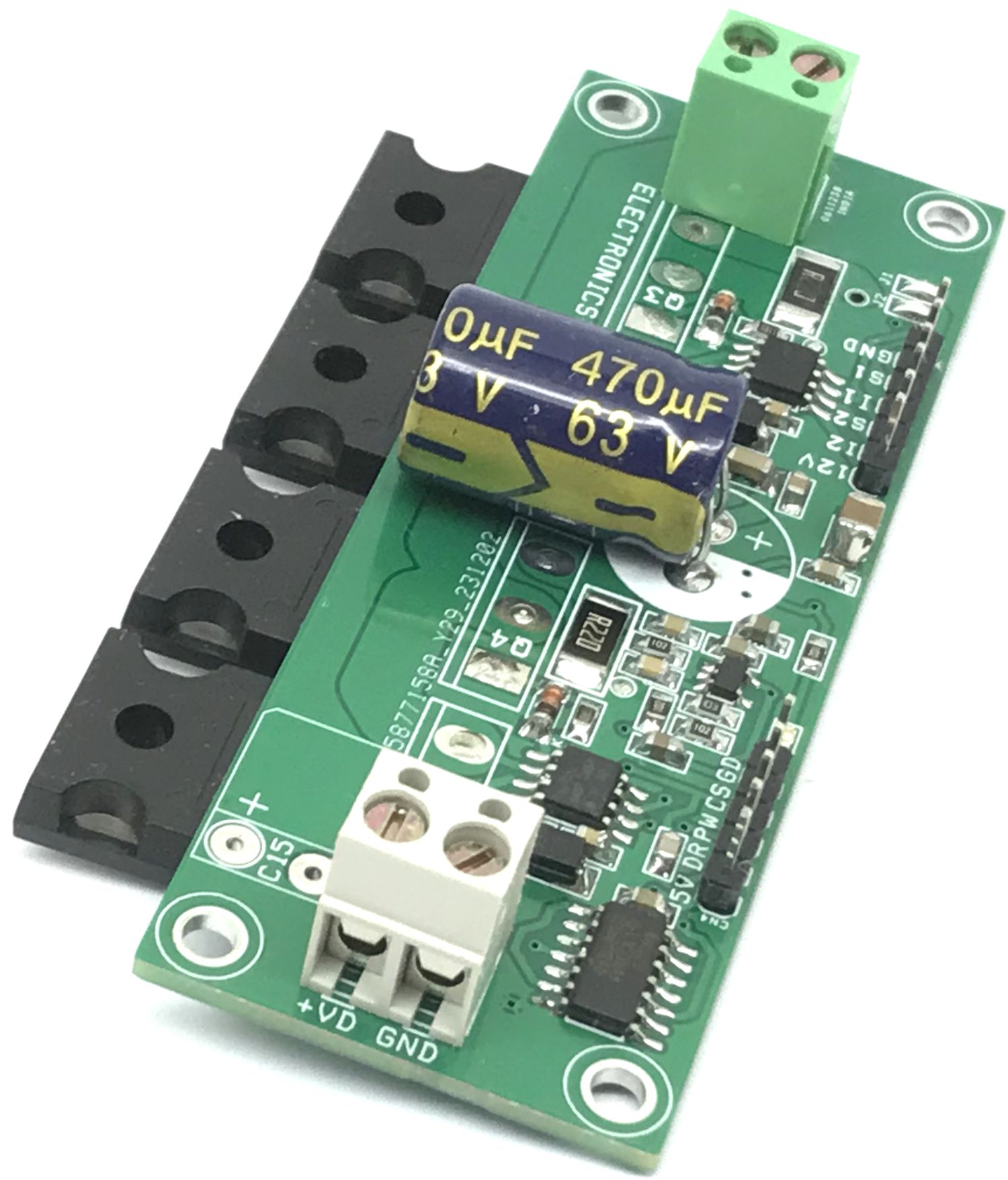
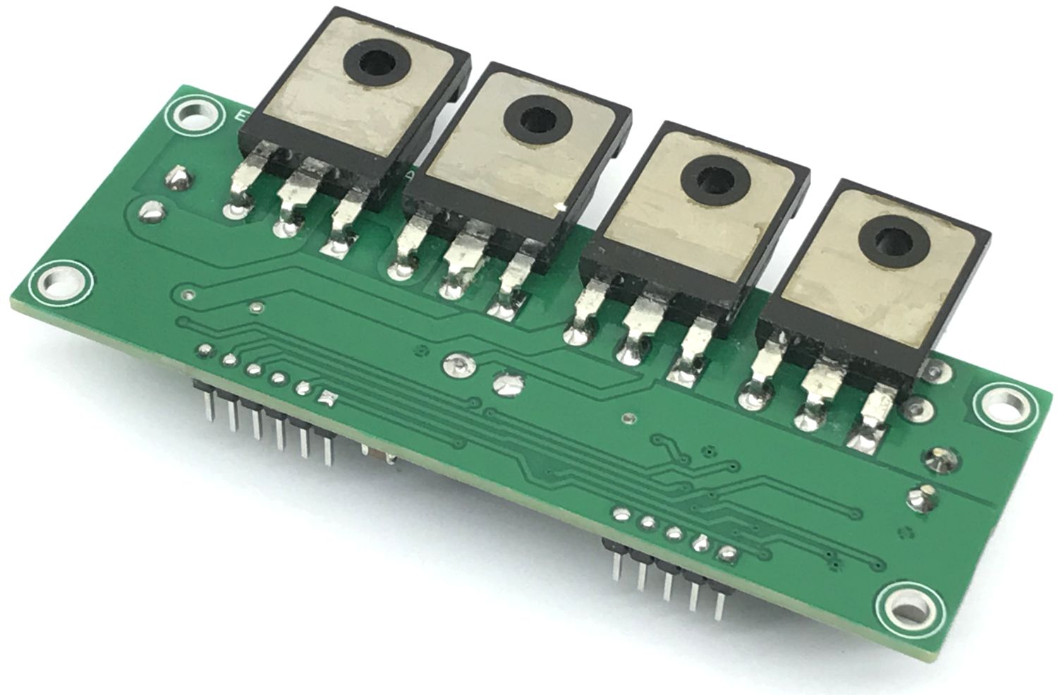
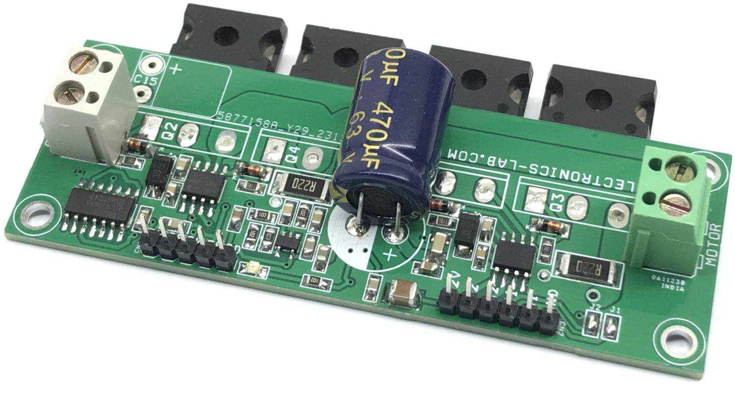
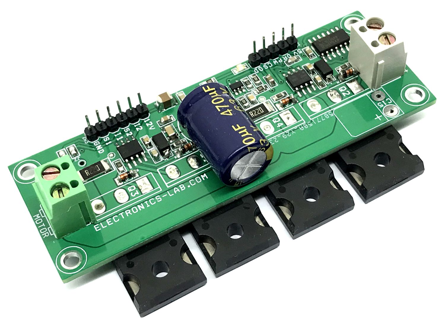
This H-bridge board is an easy-to-use brushed DC motor driver that can handle large-size motors such as wheelchair motors, and winch motors. An H-bridge is an electronic circuit that switches the polarity of a voltage applied to a load. The circuit is built using 4 x N-Channel MOSFETs, gate driver IR2104, and a logic circuit. The direction of rotation is dependent upon the polarity of the applied voltage. If you reverse the voltage, the direction of rotation reverses.
Features
Power Supply Motor 12V to 50V DC
Load Up to 10Amp Continues – Tested, Maximum 20A
Gate Driver Power Supply 12V to 15V
Logic/Current Sense Power Supply 5V
PWM Frequency Up to 20Khz
PWM Duty Cycle Input 95% to 5%
On Board Current Circuit
On Board Power LED (Gate Driver)
4 x 3 mm Mounting Holes
PCB Dimensions 91.92 x 32.70 mm
PWM and Direction Control
The project requires 2 signals to control the DC motor, a PWM for speed control and a DIR signal for direction control. The project is tested with a frequency up to 20KHz and a PWM duty cycle 95% to 5%. Both logic signals are TTL 5V compatible.
CN4: All Inputs are TTL 5V
Pin 1 5V DC for U3 Chip
Pin 2 Direction High or Low
Pin 3 PWM Duty Cycle 95% to 5% Frequency up to 20Khz
Pin 4 Current Sense Output
Pin 5 GND
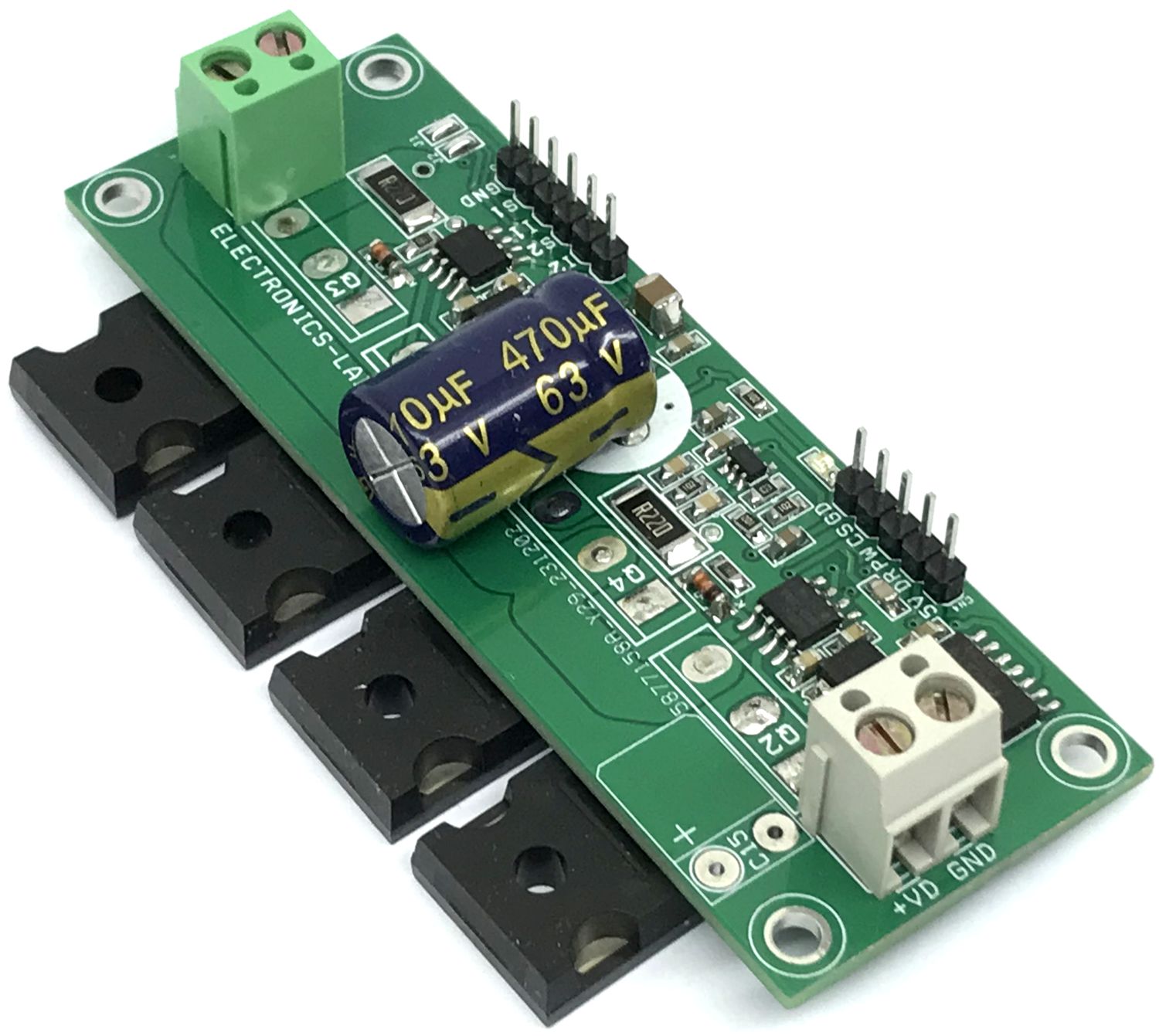
Direct Gate Driver Control: Shutdown, PWM/Logic
The project also can be controlled with direct logic signals applied to Gate driver chip IR2104, use connector CN2 for inputs, and don’t populate the U3 chip in this case.
CN2 Input Signals: All Input Signals are TTL 5V
Pin 1 = VCC 12V Power for Gate Driver
Pin 2 = IN2 PWM/Logic Input
Pin 3 = Shutdown 2 (TTL Logic High=Enable)
Pin 4 = IN1 PWM/Logic Input
Pin 5 = Shutdown 1 (TTL Logic High=Enable)
Pin 6 = GND
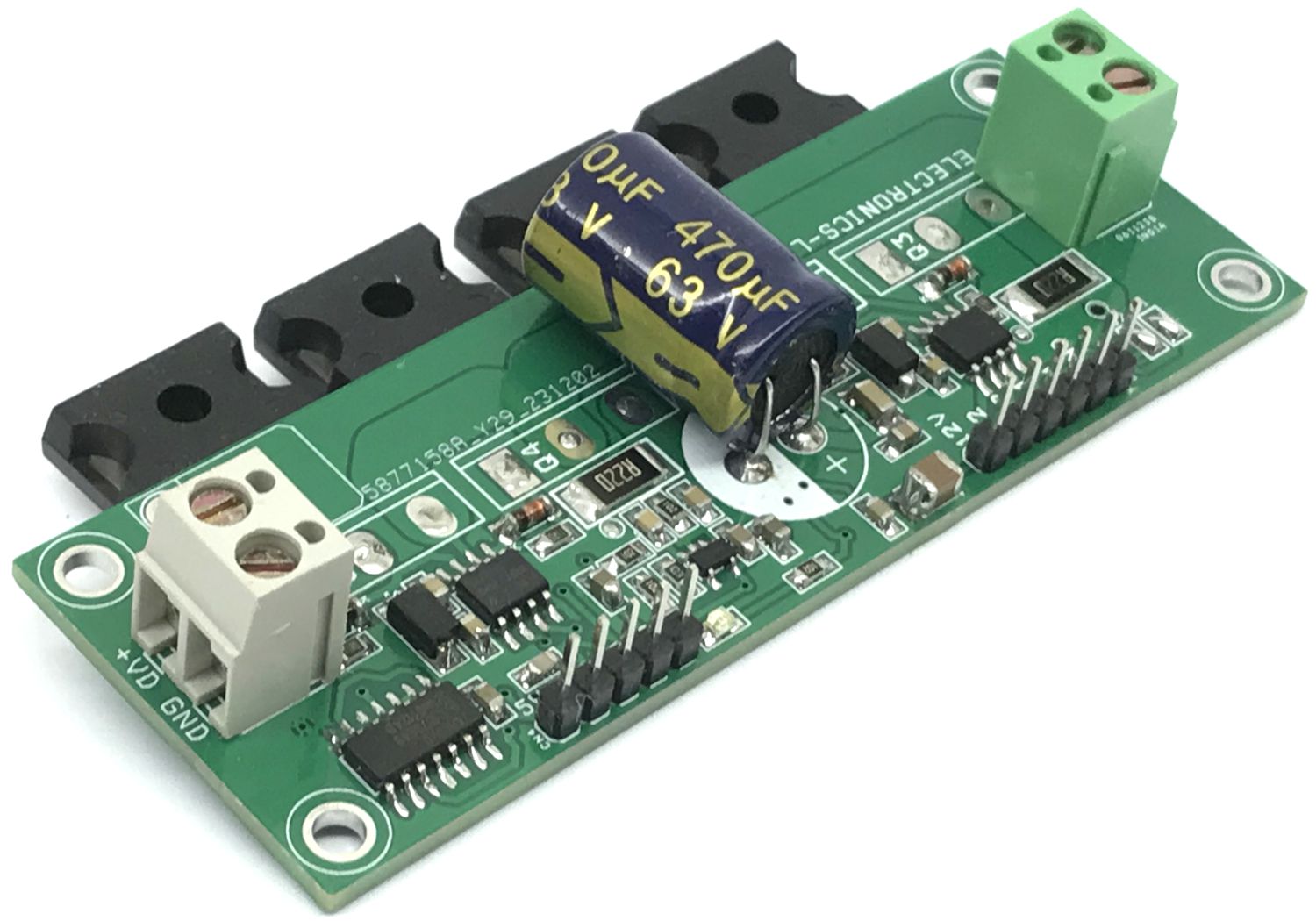
Current Sense
An optional current sense circuit can be used if required. The current sense circuit is built using OPAMP U4, which measures the current across shunt resistors R8 and R9 and provides current feedback at CN4 Pin 4. This signal can be used to detect the current flow, over current conditions etc. Current sense Output approx. 0.1V/A
Note1: If the current sense circuit is not required don’t install the following components: R5, R10, R18, R6, C12, C10, C11, and U4, Replace R8 and R9 with 0 Ohm.
Note:2: The project can handle higher voltage and current. In this case, choose appropriate MOSFETS. It is important to replace capacitors C1, C2, C3, and C15 with the required voltage rating.
Connection
CN1: Pin 1 = Motor Power Supply 12V to 50V DC, Pin 2 GND
CN2: Pin 1 = Power for Gate driver 12 to 15V, Pin 2 IN2, Pin 3 Shutdown 3, Pin 4 IN1, Pin 5 = Shutdown 1, Pin 6 = GND
CN3: Pin 1 = Motor, Pin 2 Motor
CN4: Pin 1 = 5V DC for U3 and Current Sense Circuit, Pin 2 = Direction Input TTL5V (High/Low), Pin 3 = PWM Input Duty Cycle 95% to 5%, Pin 4 = Current Sense Output, Pin 5 = GND
Jumper J1: Enable/Disable U2 (Jumper Closed = Enable)
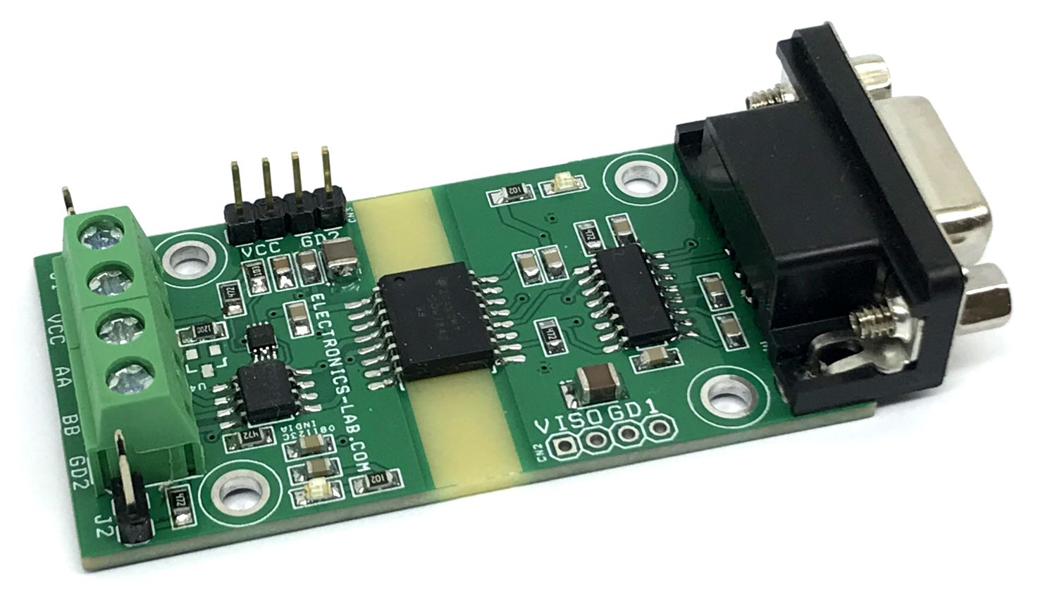
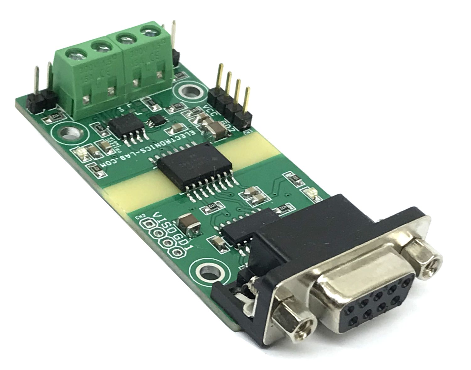
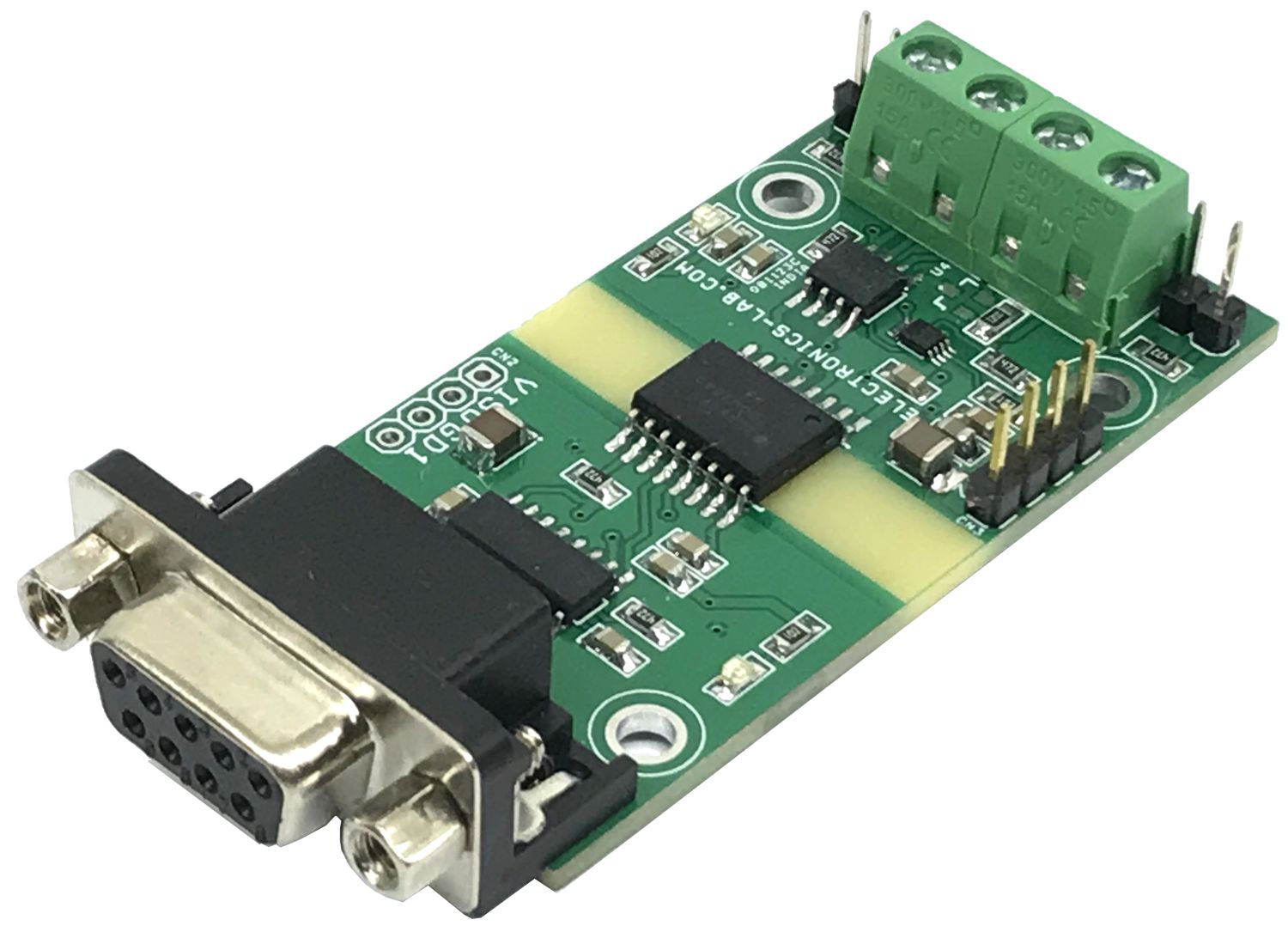
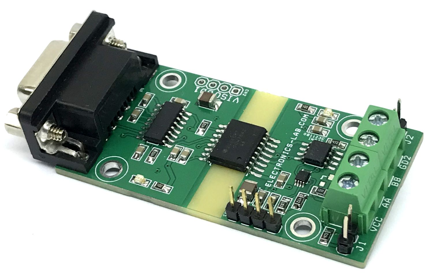
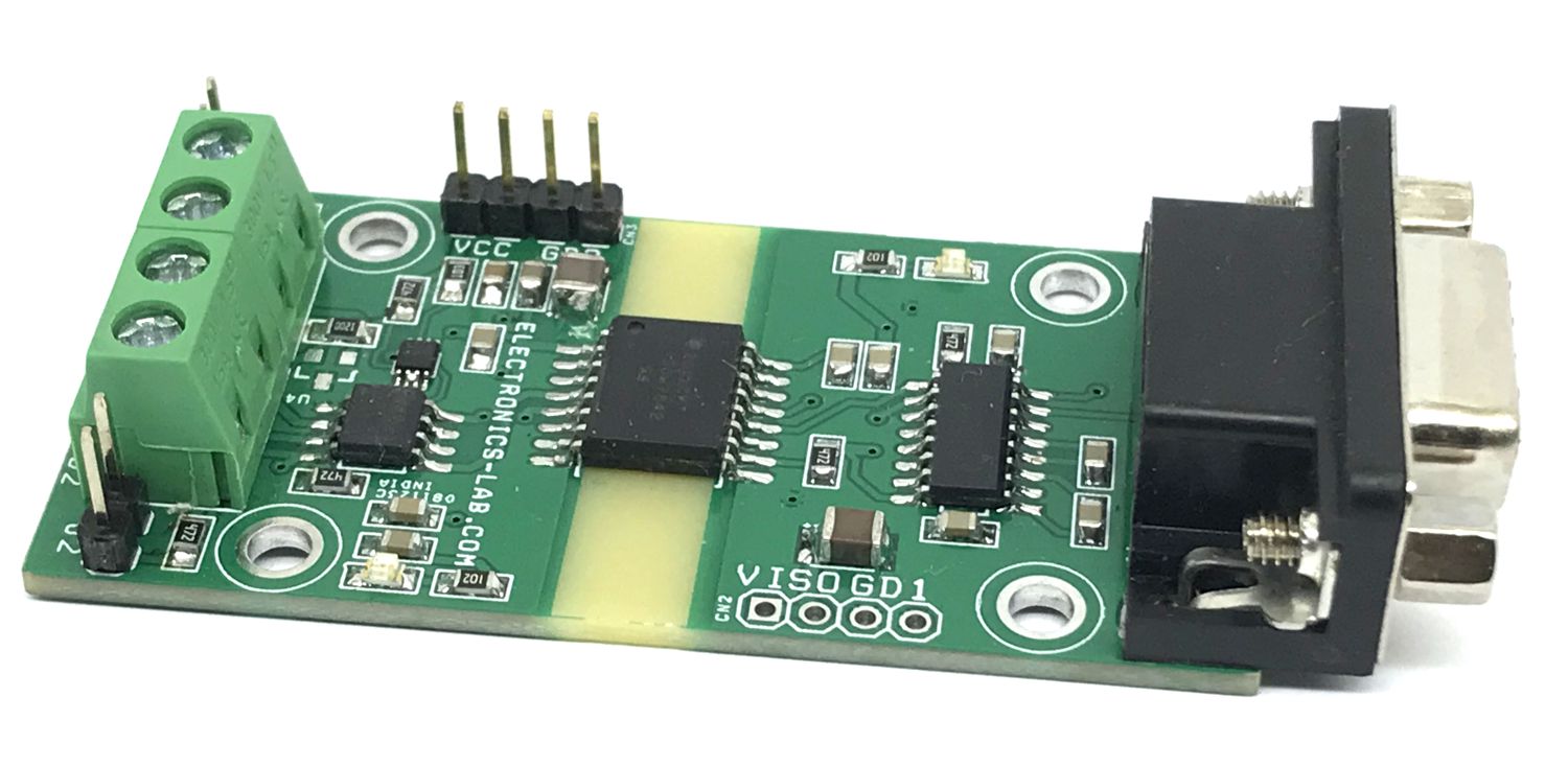
This project provides a solution for converting RS232 signaling to RS485 signaling. This allows long-distance communication since the range supported by RS232 is normally less than 50 feet while RS485’s range can exceed 1000 feet. The design features an RS232 transceiver, an RS485 transceiver, a multivibrator, and a digital isolator with integrated power to implement bidirectional half-duplex communication without any software interference. The board has been tested for up to 800 feet in length with a two-wire twisted pair cable. Up to 115200 baud rate communication between two PCs via serial port has been successful. The design features the industrial standard IEC 61000-4-2 and 61000-4-4 protection with 5000 Vrms isolation protection.
Convert RS232 to RS485 signaling for bidirectional half-duplex communication
Without any Software Interference
Industrial-level ESD Protection
Isolation: 5000 Vrms Isolation Protection.
Extend System Topology from Point-to-Point to Multi Drop
Cable Length up to 1000 Feet
Hot Plug-in Feature
4 x 3 mm Mounting Holes
PCB Dimensions 62.56 x 31.99 mm
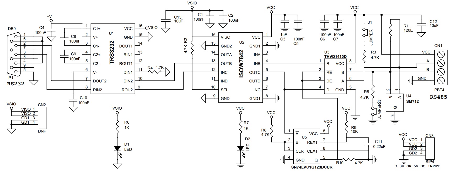
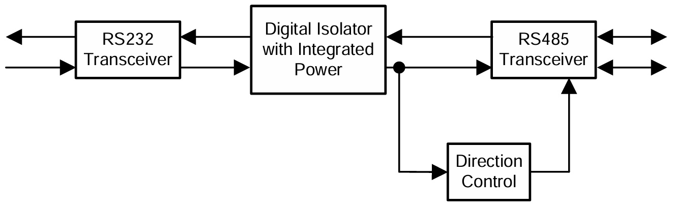
RS-232 is a widely used interface. One example is the serial port (COM port) of a PC. One drawback is that it can only support short distance communication (up to 50 ft). Some industrial applications need to extend the distance with robust communication. Converting RS-232 to RS-485 is one of the options, since RS-485 is widely used in industrial applications for long distance transmission. This project implements the conversion circuit via an RS-232 transceiver, an RS-485 transceiver, a digital isolator, and a multivibrator. The industrial-level ESD protection is also included. The simplified diagram is shown in Figure. The power of the system is provided from the RS-485 transceiver side. This supply is isolated by a digital isolator ISOW7842 and transferred to the RS-232 transceiver side. High speed RS-485 communication needs to be properly terminated and can take up to 50 mA current consumption depending on the bus loading conditions. The RS-232 transceiver TRS3232E is interfaced with the external device like a PC. The RS-232 signal is converted to the digital domain and then transferred to the other power domain by the digital isolator. In this isolated power domain, the received digital signal is converted to RS-485 signal by a RS-485 transceiver (THVD1410). In the meantime, the edge of the digital signal triggers the multivibrator SN74LVC1G123 to generate a pulse to enable the RS-485 transceiver’s transmission. In the idle state, the receiver of the RS-485 transceiver is turned on and the driver is turned off. When a valid signal shows up, the RS-485 transceiver is set into transmitter mode. Therefore, a half-duplex communication is established.
THVD1410
The THVD1410 is used for RS485 communication in this design. This device generates a compliant RS-485 standard output voltage with 3.3 V to 5 V supply and works for data transmission up to 500 kbps data rate. It has integrated ESD protection, such as ±18 kV IEC 61000-4-2 Contact Discharge and ±4 kV
IEC 61000-4-4 Fast Transient Burst immunity.
TRS3232E
The TRS3232E device comprises two RS-232-line drivers and two-line receivers with ±15-kV IEC ESD protection. This device works with a 3.3V or a 5 V supply and up to 250 kbps data rate. It meets the requirements of TIA/EIA-232-F and provides the electrical interface between an asynchronous communication controller and the serial-port connector. In this TI design, one of each line driver and receiver is used for TxD and RxD signal. The other channel is left as “no connect” with the option of being used as RTS/CTS or DTR/DSR in other applications.
ISOW7842
The ISOW7842 is a high-performance, quad-channel reinforced digital isolator with an integrated high efficiency power converter. The integrated DC-DC converter works with 3.3 V and 5 V supplies and provides up to 650 mW of isolated power at high efficiency. Like the TRS3232E configuration, the unused channels have the option of future channel extension of the application.
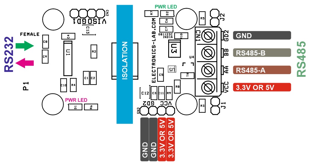
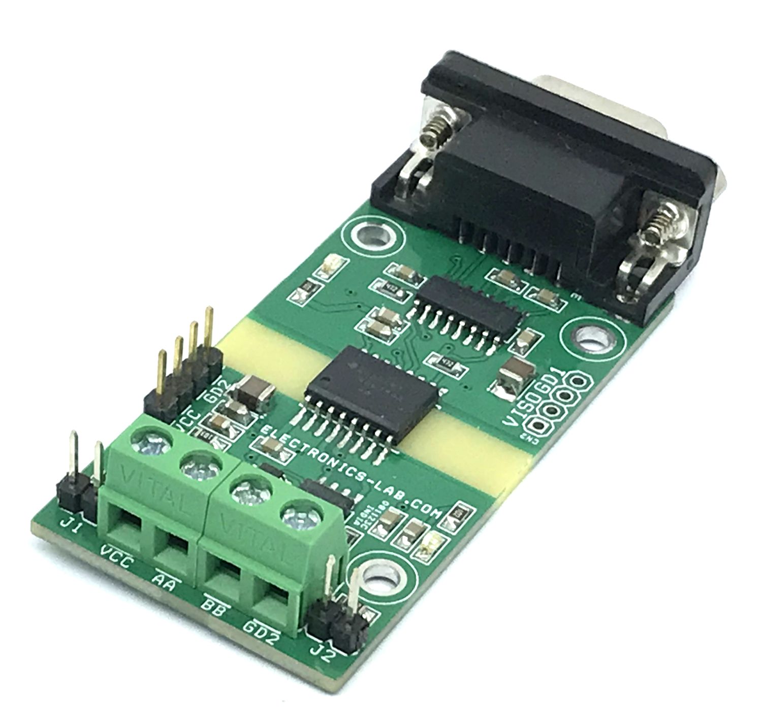
Connections
CN1: Pin 1 = VCC 3.3V or 5V DC Power Input, Pin 2 = RS485 Channel A, Pin 3 = RS485 Channel B , Pin 4 = GND
CN2: Do Note Populate
CN3: Pin 1 & Pin 2 = VCC 3.3V or 5V DC Power Input, Pin 3 & 4 = GND
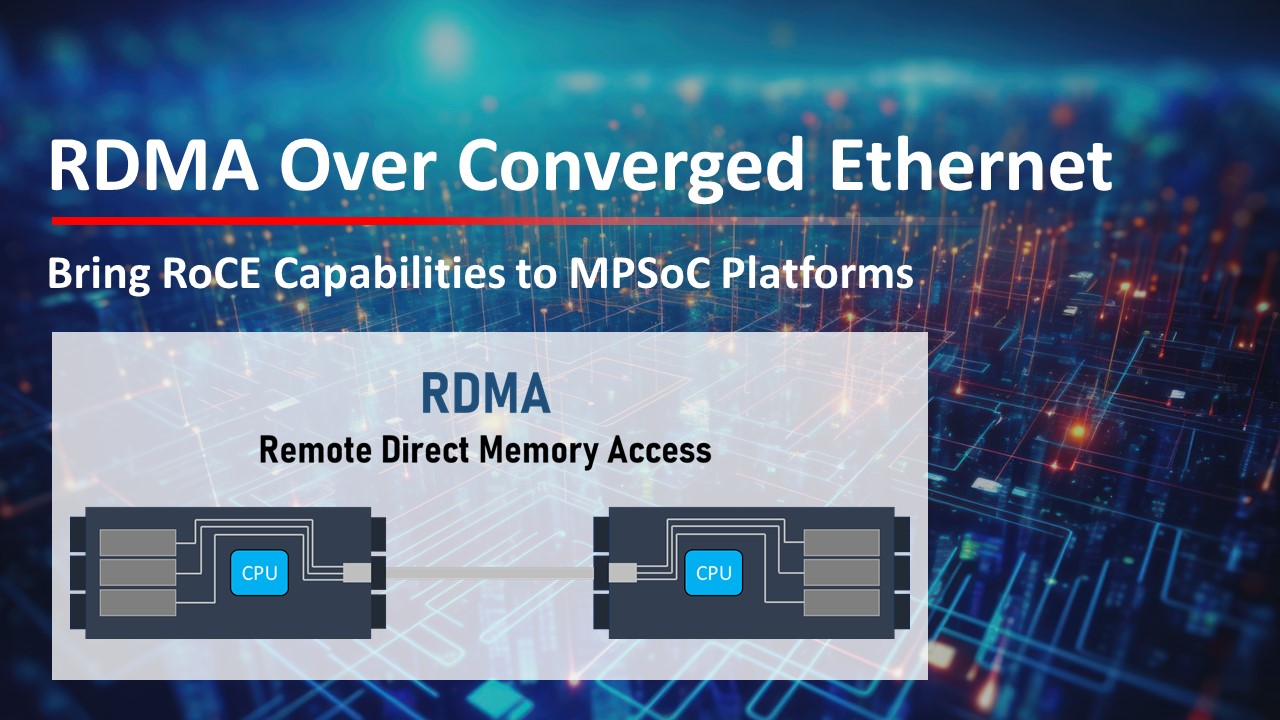
Rapid advancements in compute-intensive applications have raised the bar for a faster, more efficient, and scalable network. Remote Direct Memory Access (RDMA) over converged ethernet (RoCE) has emerged as a ground breaking technology that enables direct data transfer between systems without the intervention of CPU, reducing latency and enhancing overall system performance. iWave, an FPGA design house has taken a step further implementing 100G Ethernet solution by integrating ERNIC IP (Ethernet RDMA Network Interface Controller Intellectual Property) from AMD, bringing RDMA capabilities to their embedded computing modules portfolio.
What is RDMA over converged ethernet (RoCE)?
RDMA is a technology that allows direct memory transfers between hosts or servers without CPU involvement. This frees up CPUs for tasks like running applications and handling data processing, leading to enhanced network performance with reduced latency, CPU load, and increased bandwidth cost-effectively. While RoCE is a network protocol that allows RDMA over an ethernet network. RoCE leverages the capabilities of RDMA while utilizing the standard Ethernet infrastructure, making it an attractive choice for organizations seeking performance improvements without overtaking their existing network setups.
Types of RoCE
There are two versions of RDMA over Converged Ethernet: RoCE v1 and RoCE v2, depending on the network adapter used.
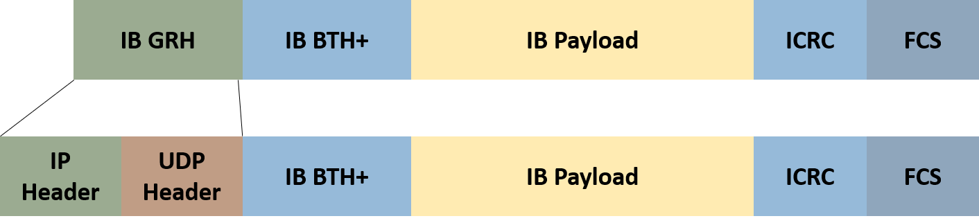
RoCE v1: This protocol allows communication between two hosts within the same Ethernet broadcast domain (VLAN). It utilizes Ethertype 0x8915, limiting standard Ethernet frames to 1500 bytes and Ethernet jumbo frames to 9000 bytes.
RoCE v2: Overcoming the limitation of RoCE v1 to a single broadcast domain, RoCE v2 introduces changes in packet encapsulation by including IP and UDP headers. This modification enables RoCE v2 to function across both L2 (Data Link Layer) and L3 (Network Layer) networks, allowing Layer 3 routing and scalability across multiple subnets. Referred to as Routable RoCE (RRoCE), RoCE v2 also introduces the capability of IP multicast.
RoCEv1 vs RoCEv2 Packet Format
ERNIC IP Enhancing RDMA Capabilities
ERNIC (Embedded RDMA enabled NIC) IP is a customizable Ethernet RDMA Network Interface Controller IP core designed to work seamlessly with AMD FPGAs, MPSoCs, and soft MAC IP implementations. It provides high throughput, low-latency, and a completely hardware offloaded reliable data transfer solution over standard Ethernet.
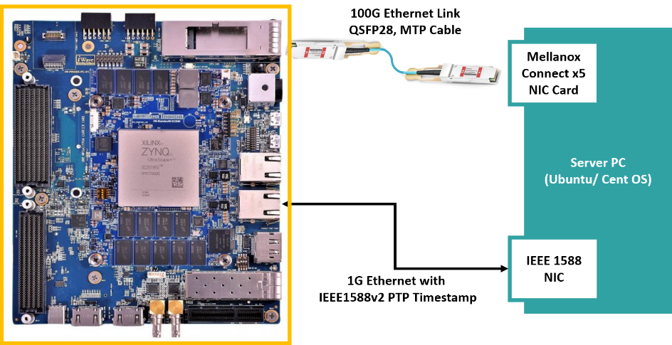
iWave, at the forefront of cutting-edge technology, has showcased the remarkable capabilities of its platform by successfully implementing 100G Ethernet solution. This was realized by using iWave’s Zynq UltraScale+ MPSoC powered development kit and integrating AMD’s ERNIC IP on the platform. The Zynq UltraScale+ MPSoC development kit is well suited for prototyping and evaluating 100G Ethernet solutions using high speed QSFP-28 connector.
The demo setup included
iWave’s Zynq Ultrascale+ MPSoC ZU19EG powered development kit
Mellanox Connect x 5 100 G NIC
Sync 1588 PTP Enabled 1G NIC
MTP Cable, QSFP-28 Modules and CAT6 RJ45 Ethernet Cable
Ubuntu 22.04 Server PC
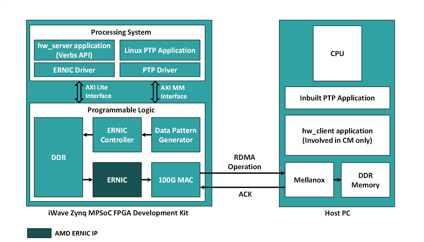
System Architecture
The high-level architecture is illustrated in the image above, with the implementation segmented between the Processing System (PS) and Programmable Logic (PL) components within the Zynq UltraScale+ MPSoC. The PS features an ARM Cortex-A53 based Hard SoC, which is used for essential system configuration, control, and diagnosis. This includes:
100G Ethernet MAC driver – Offering robust performance and low-latency support for data transmission at 100 Gb/s.
ERNIC Controller driver – Responsible for posting incoming data to DDR and notifying ERNIC IP, this driver also efficiently manages doorbell exchanges between the user application and ERNIC IP.
RDMA core and User Space Libraries – Ensures optimal performance and compatibility for RDMA operations in both kernel and user spaces.
The AMD ERNIC IP offloads the RoCEv2 Stack onto the FPGA. The ERNIC Controller manages handshaking with various modules to facilitate data transfer, generating work queue entries and ringing doorbells for the ERNIC IP. Meanwhile, the Zynq UltraScale+ MPSoC 100G Ethernet subsystem handles the MAC and Physical layers. Additionally, the Data Pattern Generator is tasked with generating both raw data and video data patterns.
PTP (IEEE 1588 Standard) timestamp is used to synchronize time between one system to another on an ethernet network. PTP timestamps enhance the performance of real-time applications by providing synchronized and low latency data exchange at nano second level.
Key highlights of the setup include:
100G Ethernet over RoCEv2 using AMD ERNIC IP
Reliable Connection Transport Type
RDMA SEND, RDMA READ, and RDMA WRITE for incoming and outgoing packets
RDMA Send with Immediate, RDMA Write with Immediate Message Types
RDMA Performance Test using XRPING and PERFTEST Applications
Custom Data Pattern Generator with RAW and Video Data Pattern
Insertion of PTP Timestamp along with Data
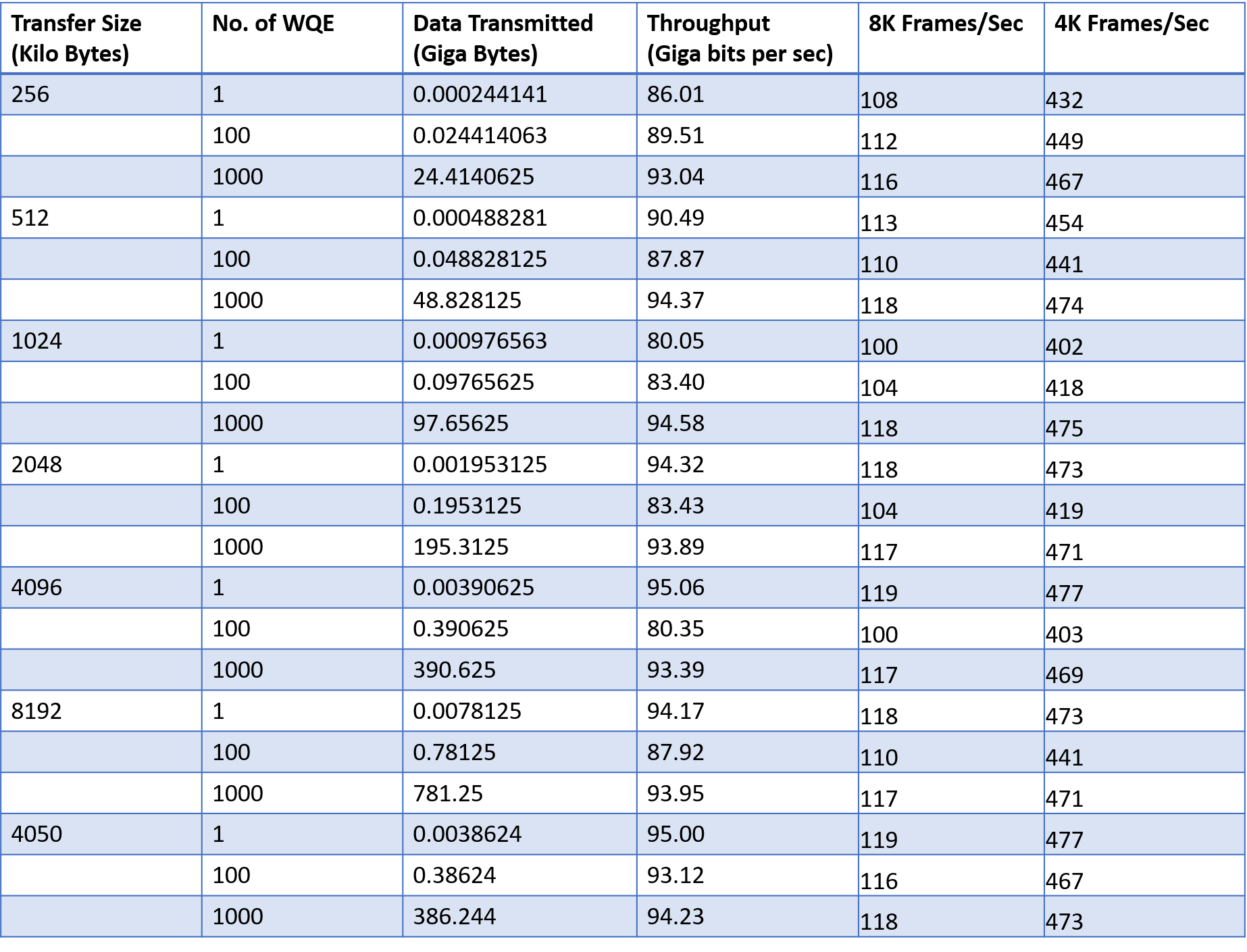
The detailed throughput statistics of the Zynq UltraScale+ MPSoC development kit to server PC video data transfer is provided in Table below. The MPSoC development platform receives 8K video @ >100 fps and 4K video @ >400fps.
Potential Applications
RDMA over converged ethernet and ERNIC IP can unlock new opportunities and capabilities across multiple industries, enhancing connectivity, performance, and efficiency in diverse applications and environments. Few of such applications are listed here:
Data Centers and Cloud Computing: Facilitate efficient communication between servers and accelerate data processing in cloud computing architectures.
Video/Image Capture and Transfer: Beneficial for multimedia applications, broadcasting, and virtual reality (VR).
Storage Solutions: Facilitate faster data transfers between storage devices and servers, contributing to improved storage system performance.
High-Performance Computing (HPC): Enhance data transfer speeds and reduce latency in HPC clusters, facilitating faster computational tasks and simulations.
IoT Edge Devices: Gather and transmit data from sensors and devices in real-time.
As the demand for faster and more efficient data transfer solutions continues to grow, RDMA over Converged Ethernet and ERNIC IP is set to play a pivotal role in shaping the future of high-performance computing.