SEGGER has released AppWizard, presenting engineers with a powerful new tool for creating complete, ready-to-run applications for the company’s popular emWin embedded graphics library. AppWizard is intuitive to operate and comes with its own built-in resource management capabilities. It facilitates the use of all of emWin’s core functions, such as the rendering of animations, language management, widgets, etc.
One of AppWizard’s notable features is the ‘What You See is What You Get’ (WYSIWYG) editor. This allows engineers to design application interfaces, along with their related interactions and events, and immediately see what these applications will actually look like. In addition, AppWizard integrates a play mode for easy testing of created applications in a simulated environment. Simply pressing F5 runs the current state of the application, just like debugging in an IDE.
The construction of embedded GUI applications with AppWizard is made very straightforward, requiring little to no prior experience with emWin or even C-programming. By applying signals and slots/interactions, the application’s behavior can be defined with ease. For example, creating a button to change a value is done with just a few clicks.
With its integrated resource management, all resources (such as fonts and images) are automatically converted to internal formats and added to the project. Resources can be stored in internal memory or offloaded to external media.
Support for board-level packages enables AppWizard to generate ready-to-use target applications. These packages include the setup of the target hardware and display for a seamless start, as well as SEGGER’s comprehensive emFile file system to make placing of resources on an SD card or some other form of external memory simple.
AppWizard outputs a bundle of C source files to work with any target system that has at least 32kByte of RAM and 128kByte of ROM. A MS Visual Studio simulation project enables debugging of the application and the adding of custom code to be carried out even if the final target hardware is not (yet) available.
“The new AppWizard streamlines the whole process of constructing even complex graphical applications, without the need for solid knowledge of how emWin works,” states Jörg Ehrle, Product Manager for emWin at SEGGER. “Our emWin PRO customers will now be able to benefit from a complete turnkey solution.”
“We have collaborated with SEGGER for many years to make emWin a key component of our software strategy for microcontrollers,” says Joe Yu, Vice President and General Manager of the Low-Power MPU & MCU Product Line at NXP® Semiconductors. “emWin’s easy-to-use API, efficiency and documentation are outstanding and easy to use within our MCUXpresso SDK packages. The introduction of new AppWizard makes it easy and fast to create stunning graphical user interfaces on our Arm® Cortex®-M microcontroller devices, from the lowest cost devices to our high-performance i.MX RT crossover platforms.”
“Renesas Electronics highly values SEGGER as a strategic partner that offers fantastic human machine interface solutions based on their emWin embedded graphics user interface,” says Daryl Khoo, Vice President of Marketing, IoT Platform Business Division at Renesas. “emWin reaches across our widely scalable RX microcontrollers and recently became a part of our Flexible Software Package (FSP) for the Renesas Advanced (RA) Family of 32-bit Arm® Cortex®-M microcontrollers. We are excited about SEGGER’s new, intuitive AppWizard GUI design tool for emWin, which offers an even greater out-of-the-box experience for our customers.”
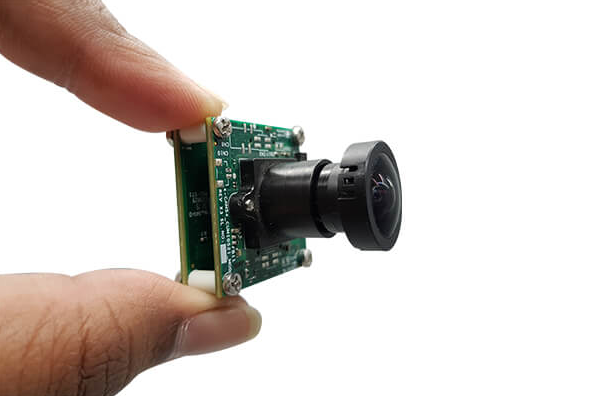
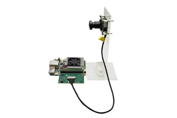
e-con Systems Inc., a leading embedded camera solutions company, today announced the launch of e-CAM50_CUCRL, a 5 MP camera board for Coral development kit from Google. e-CAM50_CUCRL houses e-con’s popular e-CAM55_CUMI0521_MOD camera module and can be directly plugged on to the Coral development kit using the supplied accessories. The camera software driver is V4L2 compliant and is available in open source.
e-CAM55_CUMI0521_MOD is based on AR0521, a 5 MP, 1/2.5″ optical format, 2.2-micron pixel size CMOS image sensor from ON Semiconductor®. The on-board high-performance Image Signal Processor (ISP) has been tuned to produce best quality images of up to 5 MP in both uncompressed YUV422 format and compressed MJPEG format. The camera module is interfaced directly to Coral i.MX8M SOM through the 4-lane MIPI CSI-2 interface supporting the maximum frame rate capabilities of the sensor.
The camera is supported by e-con’s open-source V4L2 compliant camera driver which customers can modify as per their requirements. The firmware running on the camera module configures the CMOS image sensor and ISP and communicates with the processor using e-con’s standard command control protocol. e-con’s software package contains some sample applications allowing our customers jumpstart their application development on Coral development kit immediately. e-CAM50_CUCRL is a perfect solution for customers to start their prototyping and e-con is committed to supply any volume of 5 MP camera module when our customers advance from prototyping stage to mass production stage.
e-CAM50_CUCRL is capable of streaming HD (1280 x 720) at 70 fps, FHD (1920 x 1080) at 60 fps and 5 MP (2592 x 1944) at 25 fps in uncompressed (UYVY) format. The camera produces excellent quality images consistently which is an important requirement for edge inference applications. e-con also helps our customers to choose the optics as per their application requirements.
“When combined with embedded camera technologies, AI can truly be a transformative force – whether they are deployed in smart cities and security programs or parking lots and medical devices. Being an early advocate for AI-on-edge, especially on image inference, e-con Systems combines its expertise in embedded product development and imaging to bring the best out of Coral for edge inference applications”, said Ashok Babu, President of e-con systems. “e-con is excited with the launch of first camera for Coral development kit and will come up with ready-to-deploy smart cameras powered by Edge TPU in the future”, he added.
Availability
The e-CAM50_CUCRL is currently available for evaluation. Customers interested in evaluating the product can order samples from e-con Systems’ webstore.
Raspberry Pi Foundation is responsible for the arrays of Raspberry Pis SBCs that have flawed the single board computer market and the launch of the Raspberry Pi 4 last year, shows the continuing growth for the Raspberry Pis and doesn’t seem to back down anytime soon.
The first Raspberry Pi 1 (Raspberry Pi 1 Model B) was launched in February 2012, and February 2020 marks the eight-year of innovation in a row. The goal of the Raspberry Pi was to build quality single-board computers that can be used for STEM education, computing, electronics, and even industrial at a low price point, which was something achieved throughout the years. Unfortunately, the Raspberry Pi 4 change all that with the Raspberry Pi 4 4GB RAM version priced at $55, and even the 2GB model costing $45, with only the 1GB version remaining at $35.
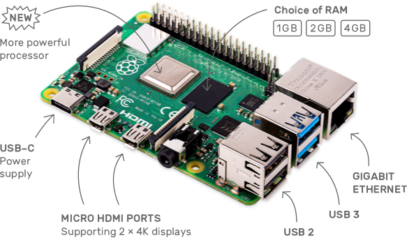
Raspberry Pi 4, Your tiny, dual-display, desktop computer
The Raspberry Pi foundation has now made an exciting announcement that drops down the price of the Raspberry Pi 4 2GB to the customary $35 without any loss in quality or performance. The previous $45 priced Raspberry Pi 4 will now cost $35 only. One question that might come up is what will now happen to the 1GB version, which cost $35, according to the Raspberry Pi foundation, nothing is going to happen to it.
In line with our commitment to long-term support, the 1GB product will remain available to industrial and commercial customers, at a list price of $35. As there is no price advantage over the 2GB product, we expect most users to opt for the larger-memory variant.
With both 2GB and 1GB of the Raspberry Pi 4, it’s only a matter of time before the poor 1GB version goes into oblivion.
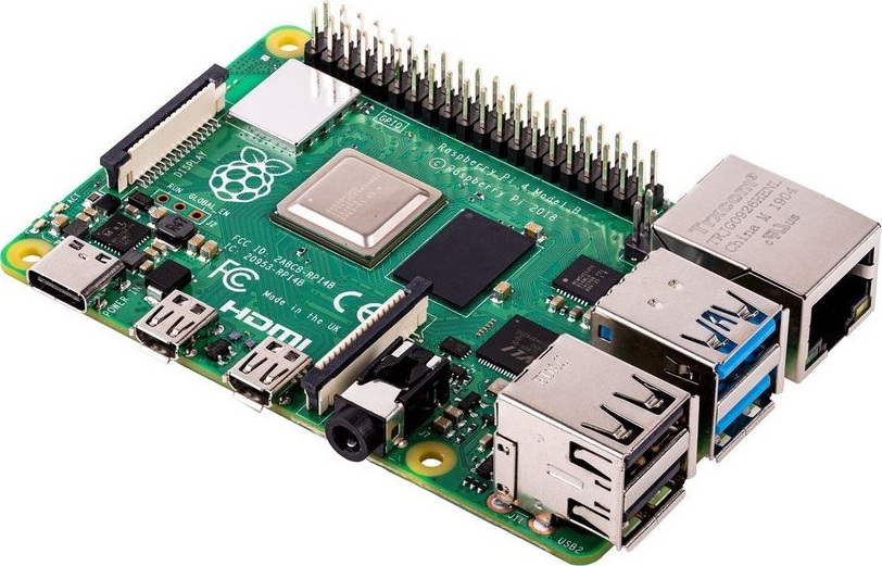
RPI 4 Type-C issues fixed
That’s not all, there is good news for prospective buyers of the diminutive Raspberry Pi 4 as the USB-C issue that stopped the device working with some power supplies has been fixed has published on The Register. After the launch of the RPi 4 in June of last year, it was observed that some of the devices complain about errors in the detection circuitry on the Pi causing certain unofficial power adapters to mistake the SBC for an audio device, and therefore not shove the expected power down the line.
Raspberry Pi co-founder and Raspberry Pi Trading CEO Eben Upton confirmed to the publication after an inquiry that the update had been rolled into a PCB Design for Manufacturing (DFM) process and it’s expected the next RPi 4 purchased will already have this new fix. Accompanying the fix is an update on the WLCSP SD card voltage switch, the new release also moved “the WLCSP SD card voltage switch to the top side” to protect it from damage, and also implemented “silkscreen tweaks to reduce solder bridging in the manufacture.”
More information about the announcement is available on the Raspberry Pi blog page, and the Raspberry 4 Model B with 2GB RAM is now available for purchase for $35 here.
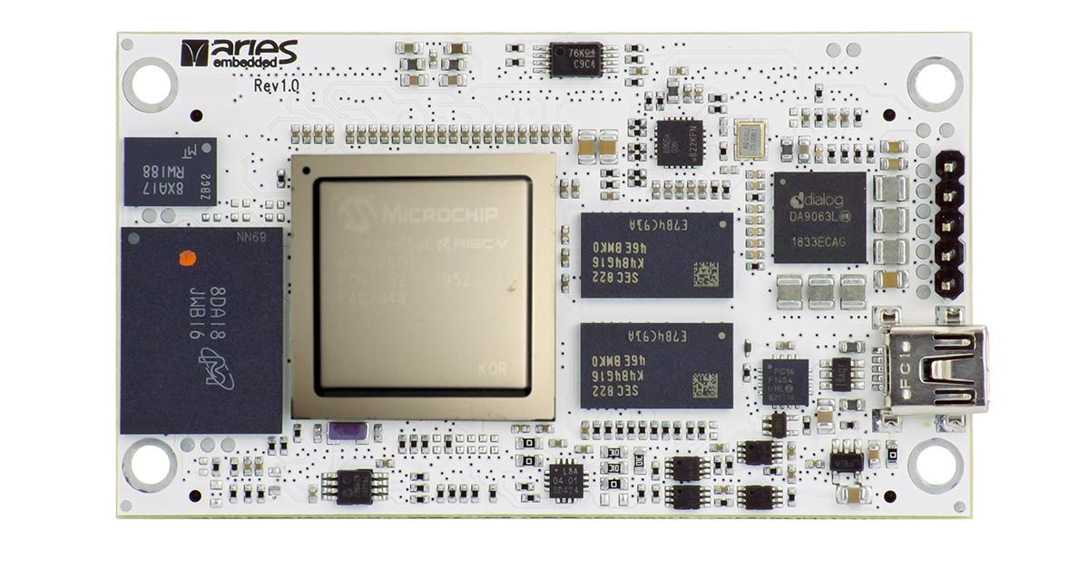
The M100PFS is based on the PolarFire SoC FPGA architecture by Microchip and combines high-performance 64-bit RISC-V cores with outstanding FPGA technology. The platform integrates a hardened real-time, Linux capable, RISC-V-based MPU subsystem on the mid-range PolarFire FPGA family, bringing low power consumption, thermal efficiency and defence grade security to embedded systems.
The RISC-V CPU micro-architecture implementation is a simple 5 stage, single issue, in-order pipeline that doesn’t suffer from the Meltdown and Spectre exploits found in common out-of-order machines. All five CPU cores are coherent with the memory subsystem allowing a versatile mix of deterministic real time systems and Linux in a single multi-core CPU cluster.
Features:
Microsemi PolarFire SoC FPGA
MPFS025T
23KLE, 68 math blocks, 4x SERDES 12.5Gbit/s, 2x PCIe root port/end point
MPFS095T, available on request
93KLE, 292 math blocks, 4x SERDES 12.5Gbit/s, 2x PCIe root port/end point
MPFS160T, available on request
161KLE, 498 math blocks, 8x SERDES 12.5Gbit/s, 2x PCIe root port/end point
MPFS250T
254KLE, 784 math blocks, 16x SERDES 12.5Gbit/s, 2x PCIe root port/end point
Quad 64-bit RV64GC cores, 667 MHz
64-bit RV64IMAC monitor core, 667 MHz
Processor I/O
2x Gigabit Ethernet
1x USB 2.0 OTG
1x MMC 5.1 SD/SDIO
2x CAN 2.0 A and B
Execute in place Quad SPI flash controller
5x multi-mode UARTs
2x SPI, 2 I2C
RTC, GPIO
5x watchdog timers
timers
Processor to FPGA Interconnect
2 64-bit AXI4 processor-to-fabric interfaces
3 64-bit AXI4 fabric-to-processor interfaces
1 32-bit APB processor-to-fabric interface
1/2/4 GByte LPDDR4 RAM dedicated to the HMS
1/2/4 GByte LPDDR4 RAM dedicated to the FPGA
32 Mbit NOR Flash
4 – 64 GByte eMMC memory
Clock distribution
default configuration:
Gigabit Ethernet
UART
CAN
SPI
I²C
USB
single 3,3V supply
size 74mmx42mm
2 x Samtec QSH-090-01-F-D-A board-to-board interconnect
Schedule & Availability
The M100PFS are currently under development, first boards are to be expected appr. in Q3/2020
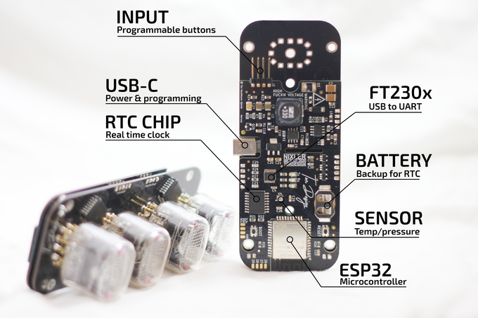
The NIXLER is being built as an open-sourceproject and designed with the DIYer in mind. I’ve included a USB to UART chip directly on the board making the NIXLER easy to reprogram. This together with the onboard ESP32 microcontroller with wifi/bluetooth, enables full customization. Hook up the NIXLER to your computer, open up the ARDUINO IDE and start modifying the code in order to realize your own version.
Use it as a super cool up/down counter or display values pulled from the web etc. I can’t wait to see what you might want to use it for. An example code will be released together with the NIXLER.
Features:
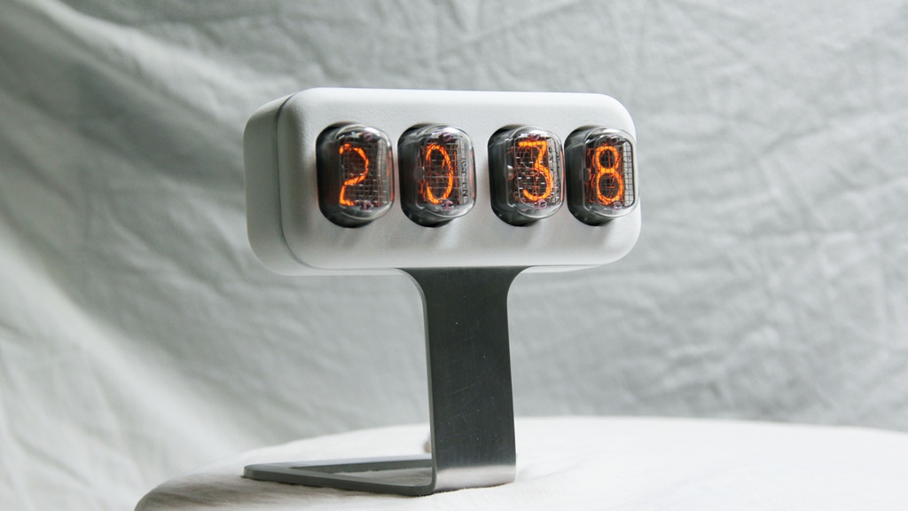
4x IN-12 Nixie tubes – cycles through hours, minutes and seconds
Two buttons interface – set time(12/24h)/date/year and other functions
4x RGB backlight LEDs
USB-C connector
Powered from a typical 5v USB wall adapter
Max 6-watt power consumption
The project is live on kickstarter and has 26 days to go. Pledges start at $199
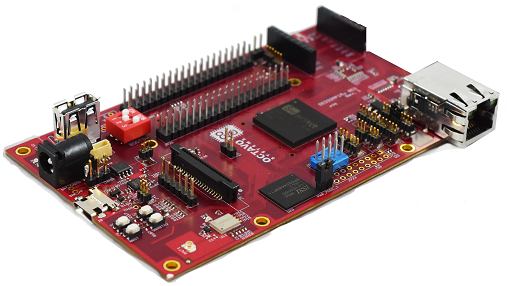
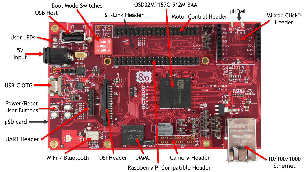
The OSD32MP1-RED is a full featured Reference, Evaluation and Development platform for the STM32MP1 based SiP, the OSD32MP15x. It provides access to a number of standard communication interfaces like WiFi and Bluetooth, 1Gb Ethernet, and CAN. It supports HDMI or DSI displays and has a connector for a camera. The OSD32MP1-RED expands easily by providing connectors that are compatible with Raspberry Pi, MikroElektronika mikroBUS™ Click, and STMicroelectronics Motor Control Header.
The on board eMMC comes preloaded with an Opensource Linux Distribution allowing you to begin development straight out of the box.
With its communication interfaces, peripherals, and expansion capabilities, the OSD32MP1-RED is a perfect platform for quickly developing IOT, high-end HMI, or real time control applications.
Features:
Full Featured Reference, Evaluation, Development Platform
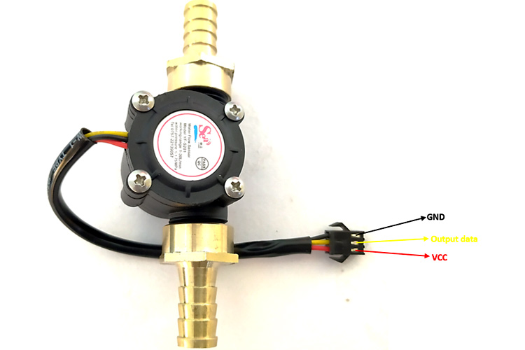
Flow rate and volume helps tell the amount of fluid going into, or through a particular vessel. For certain process automation applications, this simple-sounding fluid measurement task is so critical to the success of the project that, failure to get it right, could bring the entire process to its knees. This is why for today’s tutorial, I thought it will be cool to look at this nice water flow sensor; the YF-S201, and its use in an Arduino based project.
The YF-S201 water flow sensor consists of a pinwheel sensor that measures the quantity of liquid passing through it.
The sensor uses the principles of electromagnetism, such that, when liquids flow through the sensor, the flow action impacts the fins of a turbine in the sensor, causing the wheel to spin. The shaft of the turbine wheel is connected to a hall effect sensor so that with every spin, a pulse is generated, and by monitoring that pulse with a microcontroller, the sensor can be used in determining the volume of fluid passing through it.
Measuring Water Flow Rate and Volume using Arduino and a Flow Sensor – [Link]
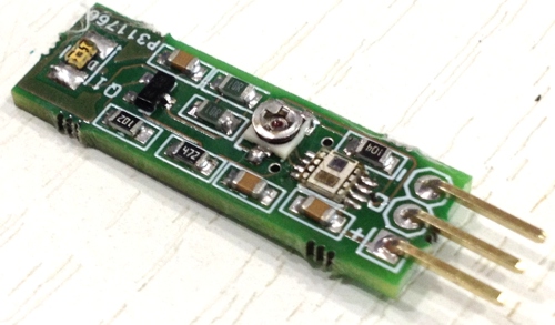
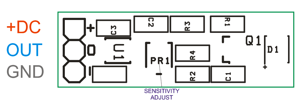
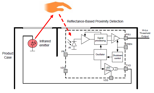
This reflective sensor module is a high-performance 0-5 cm active proximity detector. The sensor can provide a range up to 50cm with higher current infra-red LED and current limit resistor R2, R4 used across IR LED. Because the sensor operates on an absolute reflectance threshold principle, it avoids the ambiguity of motion-based proximity systems. The Si1102 consists of a patented, high-EMI immunity, differential photodiode and a signal-processing IC with LED driver and a high-gain optical receiver. Proximity detection is based on measurements of reflected light from a strobed. The sensor board is based on Si1102 from Silicon Labs. The Si1102 is an active optical reflectance proximity detector with a simple on/off digital output whose state is based upon the comparison of reflected light against a set threshold. An LED sends light pulses whose reflections reach a photodiode and are processed by the Si1102’s analog circuitry.
Reflectance based Proximity Sensor using Si1102 – [Link]
This reflective sensor module is a high-performance 0-5 cm active proximity detector. The sensor can provide a range up to 50cm with higher current infra-red LED and current limit resistor R2, R4 used across IR LED. Because the sensor operates on an absolute reflectance threshold principle, it avoids the ambiguity of motion-based proximity systems. The Si1102 consists of a patented, high-EMI immunity, differential photodiode and a signal-processing IC with LED driver and a high-gain optical receiver. Proximity detection is based on measurements of reflected light from a strobed. The sensor board is based on Si1102 from Silicon Labs. The Si1102 is an active optical reflectance proximity detector with a simple on/off digital output whose state is based upon the comparison of reflected light against a set threshold. An LED sends light pulses whose reflections reach a photodiode and are processed by the Si1102’s analog circuitry.
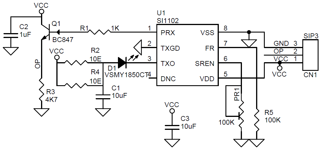
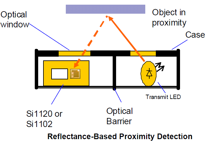
If the reflected light is above the detection threshold, the Si1102 asserts the active-low PRX output to indicate proximity. This output can be used as a control signal to activate other devices or as an interrupt signal for microcontrollers. Note that when the proximity of an object nears the pre-set threshold, it is normal for the PRX pin to alternate between the on and off states. To achieve maximum performance, high optical isolation is required between two light ports, one for the transmit LED and the other for the Si1102. The Si1102 light port should be infrared-transmissive, blocking visible light wavelengths for best performance. This dual-port active reflection proximity detector has significant advantages over single-port, motion-based infrared systems, which are good only for triggered events. Motion detection only identifies proximate moving objects and is ambiguous about stationary objects.
The Si1102 allows in- or out-of proximity detection, reliably determining if an object has left the proximity field or is still in the field even when not moving. The Si1102 proximity detector is designed to operate with a minimal number of external components. The trimmer potentiometer is used to set the proximity detection threshold. The Si1102 periodically detects proximity at a rate that set programmed by a single resistor (R5). The part is powered down between measurements. The resulting average current, including that of the LED, can be as low as a few microamperes, which is well below a typical lithium batteries self-discharge current of 10 μA, thus ensuring the battery’s typical life of 10 years. When enabled (SREN driven low by a microcontroller or PR1 pull-down potentiometer exists), the Si1102 powers up, and then pulses the output of the LED driver.
Light reflected from a proximate object is detected by the receiver, and, if it exceeds a threshold set by the potentiometer at the SREN pin, the proximity status is latched to the active low PRX output pin. The output is updated once per cycle. The cycle time is controlled through the optional R5 resistor.
Strobe Frequency Resistor (R5)
A resistor to VSS controls the proximity-detection cycle frequency. With no resistor, the sample frequency is, at most, 5.0 Hz. With FR shorted to VSS the sample frequency is typically 250 Hz. With a 100 kΩ resistor, the sample frequency is typically 7 Hz, maximum 30 Hz. The voltage on FR relative to the ground is only about 30 mV.
Note: It is important to have an optical barrier between the LED and the Si1102. The reflection from objects to be detected can be very weak since, for small objects within the LED’s emission angle, the amplitude of the reflected signal decreases in proportion with the fourth power of the distance.
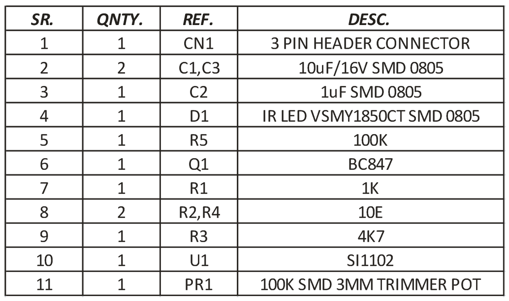
Features
Supply 5V DC
Output High TTL Signal When Object Detect
Infra-Red 100mA LED 0805 Package
Output normally high; goes low when proximity is detected.
Sampling Strobe Rate 30Hz (Can be alter using R5, Refer datasheet of IC Si1102)
Detection Range 5cm (50cm Range Possible with Higher Current IR LED Proper Optics)
Flow rate and volume helps tell the amount of fluid going into, or through a particular vessel. For certain process automation applications, this simple-sounding fluid measurement task is so critical to the success of the project that, failure to get it right, could bring the entire process to its knees. This is why for today’s tutorial, I thought it will be cool to look at this nice water flow sensor; the YF-S201, and its use in an Arduino based project.
The YF-S201 water flow sensor consists of a pinwheel sensor that measures the quantity of liquid passing through it.
YFS201
The sensor uses the principles of electromagnetism, such that, when liquids flow through the sensor, the flow action impacts the fins of a turbine in the sensor, causing the wheel to spin. The shaft of the turbine wheel is connected to a hall effect sensor so that with every spin, a pulse is generated, and by monitoring that pulse with a microcontroller, the sensor can be used in determining the volume of fluid passing through it.
As the microcontroller for today, we will use the Arduino Uno. The Uno will be used to count the number of pulses detected over time and calculate the flow rate (in liters/hour) and total volume of fluid that has passed through it using the total number of pulses. The result, flow rate and volume, will then be displayed on a 16×2 LCD so as to provide a visual feedback to the user. If the 16×2 LCD is not available, you can view the data over the Arduino Serial Monitor.
At the end this tutorial, you would know how to use the YF-S201 flow sensor with the Arduino.
Required Components
The following components are required to build this project:
YF-S201 Water Flow Sensor
Arduino UNO (or any other compatible board)
16×2 LCD Display
Jumper Wires
Breadboard
Power Bank or Battery Pack.
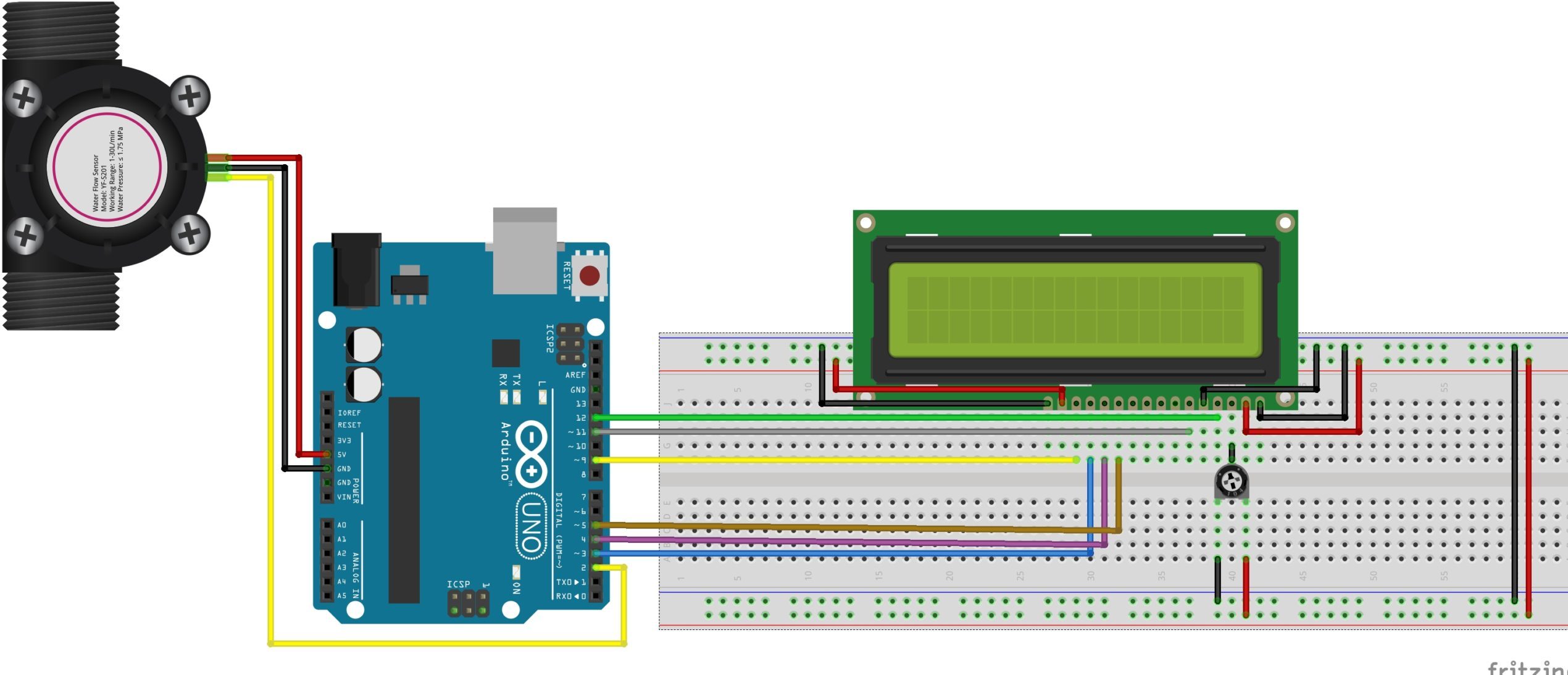
Schematics
Connect the components as shown in the schematics below:
Schematics
To make reading the sensor and calculating flow easy, the interrupt feature of the Atmega328p on the Ardunio is employed, as such, the signal pin of the YF-S201 is connected to one of the interrupt-enabled IOs of the Uno (in this case, pin D2). The LCD, on the other hand, is connected in a 4-bit mode to the Arduino. To save some time on connections, you could also decide to use an I2C enabled version of the 16×2 LCD display. For this, you will only need to connect 4 wires from the display to the Arduino. It will, however, call for some modification in the code, so be sure you can handle it before making that decision.
A breakdown of the connection showing how the components are connected, pin-to-pin, is provided below;
Double-check the connections to make sure everything is as it should be before proceeding to the next section.
Code
The idea behind the sketch is simple: monitor the signal pin of the YF-S201 to detect when the hall sensor is triggered (flow is detected) and increment a variable to show the increased inflow. However, to do that efficiently and accurately, we will use the interrupt feature of the Arduino such that whenever the hall sensor detects the rotating magnet, a rising edge interrupt is fired and registered by the Arduino. The total number of interrupts fired over a particular time is then used in generating the flowrate and the total volume of liquid that has traveled through the flow meter.
Since the flow determination is pretty straight forward, the only library we will use for this tutorial is the Arduino Liquid Crystal library. The library contains functions that make it easy to interface the 16×2 LCD with an Arduino. The library is included with the Arduino IDE but in case it’s not, it can be installed via the Arduino IDE Library Manager.
With the library installed, we then move to write the Arduino Sketch for the project.
As usual, I will go over the code and explain parts of it.
The code starts with the inclusion of the Liquid crystal library:
#include <LiquidCrystal.h>
It is followed by the declaration of some variables that will be used to store data later and the creation of an instance of the liquid crystal library.
Next, we create the flow() function. This function is called whenever the interrupt is detected and it will increment the flow counter which will serve as an indication of the flow rate.
void flow () // Interrupt function
{
   flow_frequency++;
}
Next, we write the void setup() function. We start the function by including initializing serial communication so as to have access to the serial monitor for debugging purposes.
Serial.begin(9600);
Next, we declare the Arduino pin to which the signal pin of the flow sensor is connected, as an input pin. We create a pull-up on the pin by setting it “HIGH” and set up a “Rising” edge interrupt on it with the flow() function we created earlier as the callback.
We wrap up the setup function by calling the millis() function to keep track of the time since flow rate as a measure of the flow within a particular time frame.
The loop starts by comparing how much time has elapsed since the last loop. The flow frequency, obtained via the interrupt action, is then divided by time (in minutes) and the value is displayed as the flowrate. The value is also added to the existing volume(vol) and displayed as the total volume of fluid that has passed through the sensor.
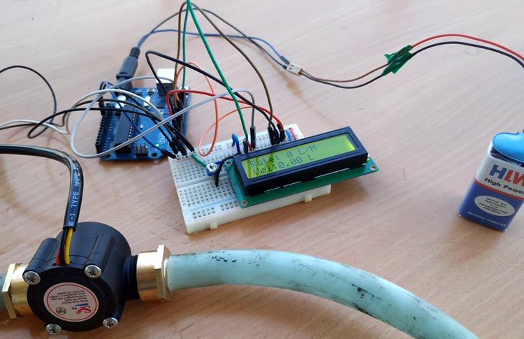
Go over your connections to be sure everything is as it should be. With this done and the code complete, connect the hardware to your computer and upload the code to the Arduino board. If successful, you should see the display come up as shown in the image below.
Connect some pipes to it using whatever means is easy for you and pass some water through the flow sensor. You should see the flowrate being displayed on your screen, vary with the intensity of water flow, and you should also see the volume increase as more water flows through it.
If you don’t have the tubes/pipes for water around at that instant, you can blow some air into the sensor. You should hear the rotor in spin and the values on the LCD should increase.
Flowrate/ volume metering is a very important part of several industrial and even individual consumer processes. It provides to not only monitor consumption but also meter supply and I believe applications like smart water meters and automated fluid dispensers should give you tons of insights into how this seemingly basic project could be transformed into an amazing super useful product.
That’s it! feel free to reach me via the comments section for help with any challenge you might have replicating the project.