Octavo Systems OSD32MP15x System In Package Releases into Production with Higher Performance and Two New Development Platforms
Octavo Systems, an ST Authorized Partner, has expanded its support of the OSD32MP15x System in Package, the smallest available STMicroelectronics STM32MP1 module, with a production release at speeds up to 800MHz, and two new development boards.
OSD32MP15x System in Package In Production at Speeds Up to 800MHz
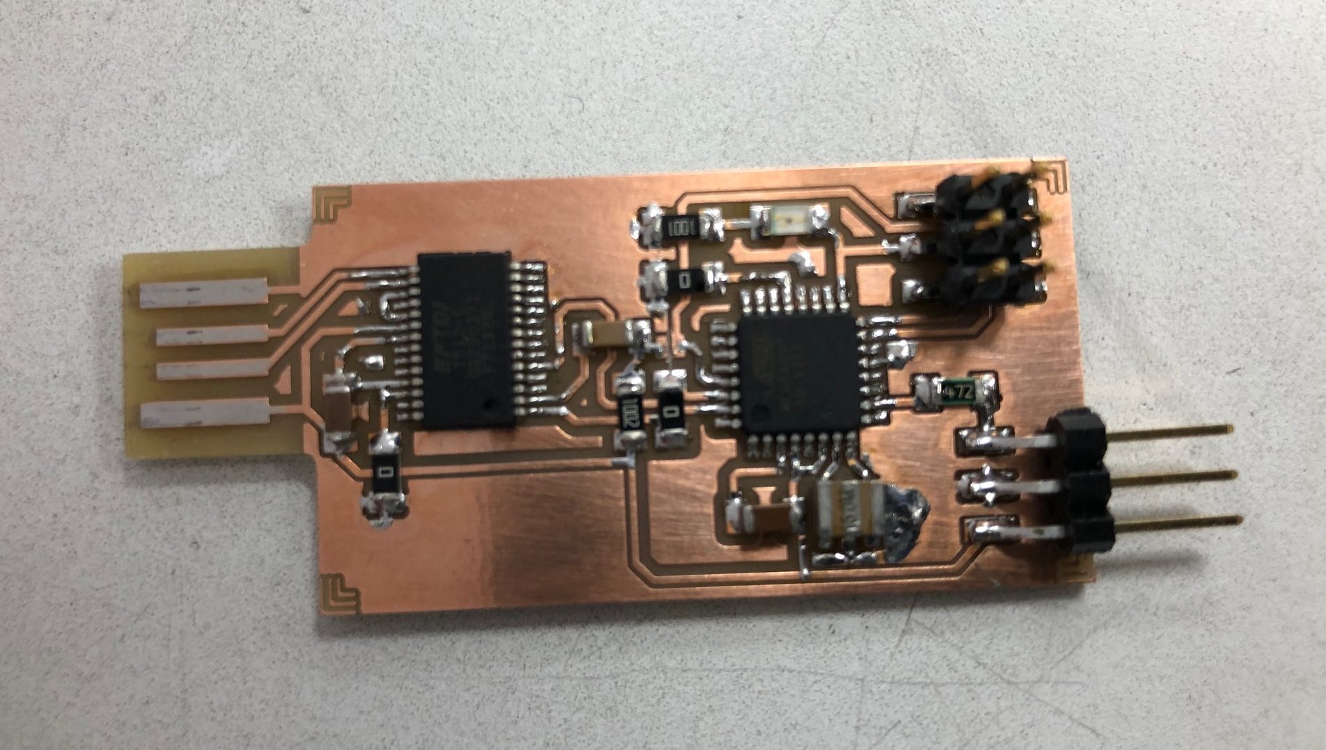
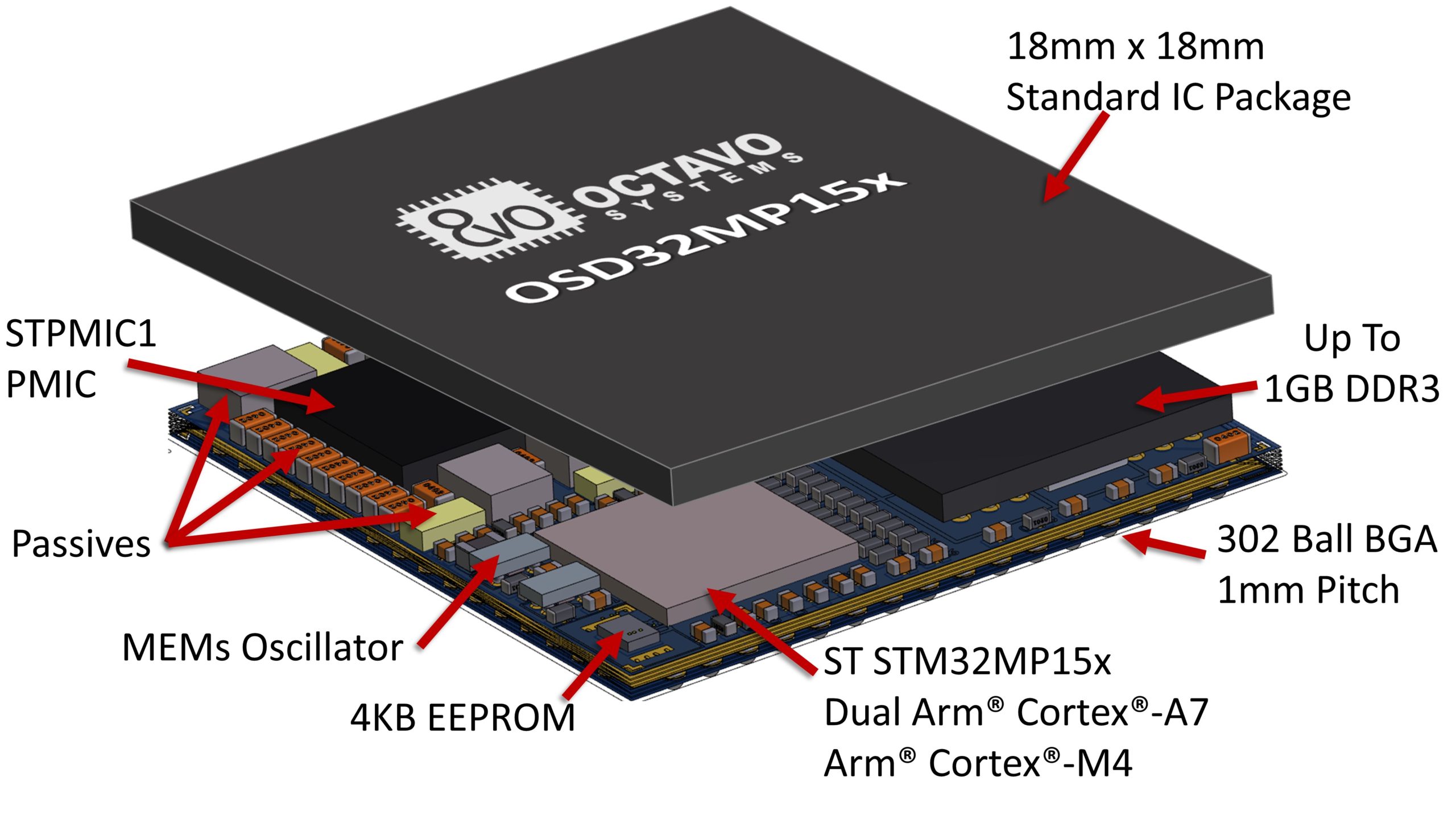
The OSD32MP15x System in Package has entered full production and can be ordered through Octavo Systems distribution partners now for delivery by the end of March. The OSD32MP15x, already shipping to customers for engineering development, integrates the STM32MP1 Dual Core Arm® Cortex® A7 + M4 microprocessor, up to 1GB of DDR3L RAM, STPMIC1A Power Management IC, EEPROM, MEMs Oscillator, and over 100 passives into a production cost saving, BGA Package. The OSD32MP15x provides complete access to all the features and performance of the STM32MP1, including the recently announced 800MHz clock speed, while removing tedious tasks like DDR routing and power sequencing. At 18mm x 18mm, the OSD32MP15x is up to 64% smaller than an equivalent system made from discrete components.
“The Octavo Systems OSD32MP15x SiP solution delivers MPU performance while allowing customers to remove complexity from their designs thanks to the MCU-like implementation, so they can focus on the value-added features of their applications,” said Ricardo De Sa Earp, General Manager of the Microcontroller Division, STMicroelectronics. “The OSD32MP15x SiP’s small size makes it ideal for space-constrained environments, while also optimizing system cost thanks to the ability to use 4 layer PCBs.”
Features
- Integrated into a single BGA Package:
- STMicroelectronics STM32MP15x microprocessor SoC with Dual Arm® Cortex® A7 and Arm® Cortex® M4
- STPMIC1 Power Management IC (PMIC)
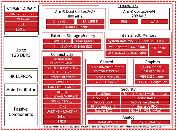
- up to 1GB DDR3L Memory
- 4KB Non-Volatile EEPROM
- Low power MEMS Oscillator x2
- Over 100 Passives
- ST32MP15x Features:
- Arm® Cortex®-A7 up to 800MHz x2
- Arm® Cortex®-M4 up to 209MHz
- NEON™SIMD Coprocessor x2
- TrustZone®
- USB 2.0 HS + PHY x2
- Ethernet 10/100/1000
- CAN FD/TTCAN x2, UART x4, USART x4,SPI x6, I2C x6, SAI x4, QSPI, SPDIF, I2S x3
- eMMC/SD/SDIO Ports x3
- GPIO x148
- 24-bit RGB Display, MIPI DSI
- Camera Interface
- 22 Channel 16-bit ADC x2, 12-bit DAC x2
- Access to all signals of the STM32MP1 TFBGA 361 package
- STPMIC1 Power Management IC Features:
- Single Voltage Input: 2.8V-5.5V
- Integrated Boost: 5.2V
- System Power: Buck LDOx4, Power Switch x2
- 302 Ball BGA (18mm x 18mm)
- 16 x 16 grid, 1mm Pitch
- Case Temp Range: 0° to 85°C, -40° to 85°C
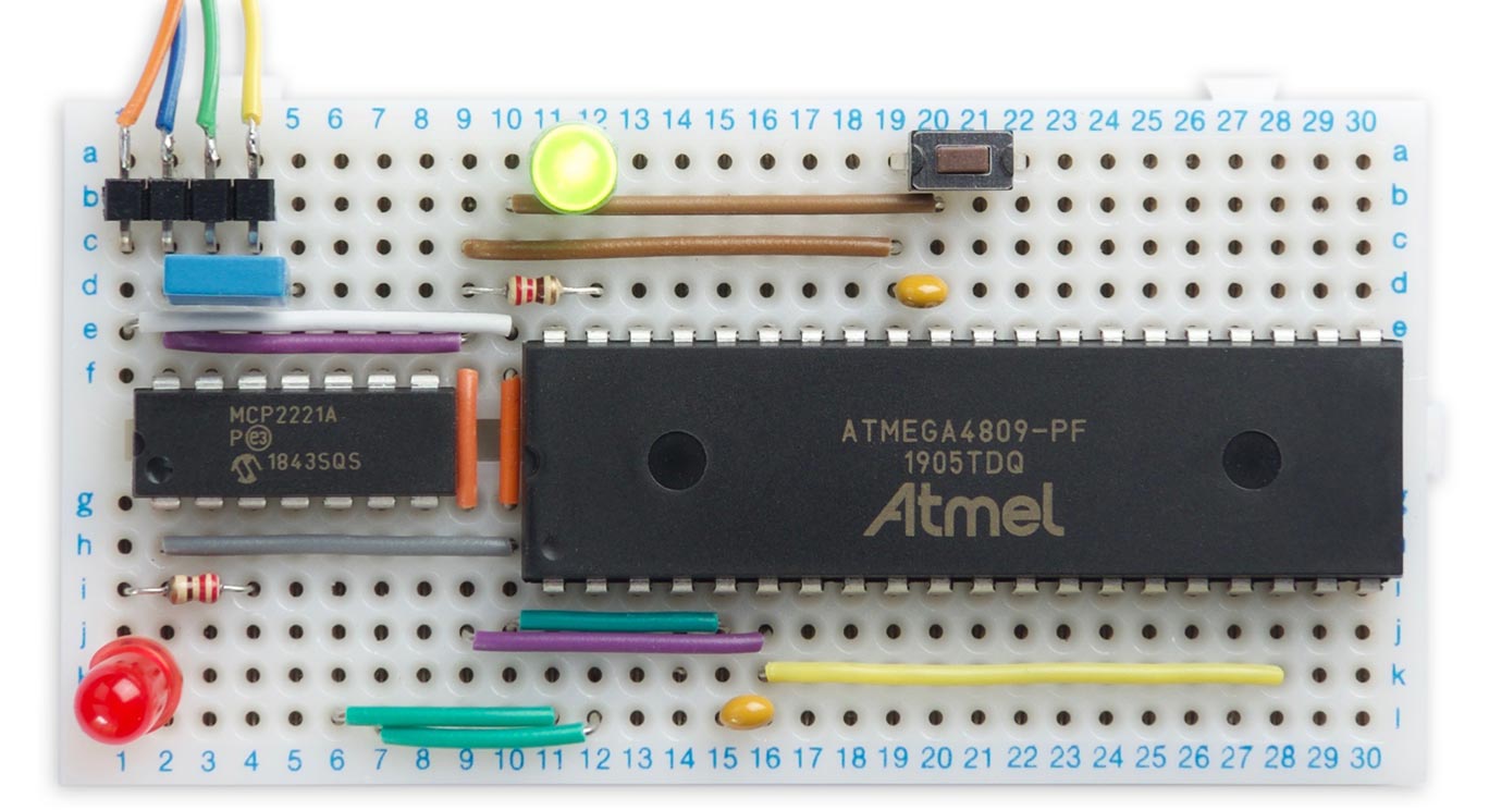
OSD32MP1-BRK Flexible Prototyping Platform
Octavo Systems also announced two hardware platforms to speed customers’ development with the OSD32MP15x. The OSD32MP1-BRK, a breakout platform, provides easy access to the I/O on the STM32MP1. The OSD32MP1-BRK features the OSD32MP157C-512M-BAA System in Package, a microSD card, 32KHz crystal, a USB port, and 2 2×30 100 mil (2.54mm) spaced headers. “The OSD32MP1-BRK provides designers a completely flexible prototyping platform. By maximizing the number of I/O that are brought out, designers can quickly build a proof of concept that more closely matches their actual system without creating their own board”, said Erik Welsh, CTO of Octavo Systems. “And since the board uses standard 100 mil headers, designers can prototype everything on a breadboard!” The OSD32MP1-BRK is designed and manufactured by Allied Component Works, LLC, a member of the Octavo Systems partner network. The product ships in April with all design files freely available on the Octavo Systems web site.
OSD32MP1-RED Complete Development Platform
The second development platform is the OSD32MP1-RED Reference, Evaluation and Development board. Developed by Octavo Systems, and shipping in May, it features the OSD32MP157C-512M-BAA SiP, a WiFi and Bluetooth Module, 1GB Ethernet, 8GB eMMC, and HDMI. The OSD32MP1-RED expands easily by providing connectors that are compatible with Raspberry Pi, MikroElektronika mikroBUS™ Click, and STMicroelectronics Motor Control Header. The OSD32MP1-RED also provides connectors for a DSI display and a camera.
“The OSD32MP1-RED is a great platform for anyone developing IoT applications or applications needing a high-end HMI,” adds Greg Sheridan, VP of Strategy for Octavo Systems. “With the connectors and peripherals provided the OSD32MP1-RED makes it easy to quickly begin prototyping your system.”
more information: octavosystems.com