Meet LoraPaper, A Weather Station That Runs On No Batteries!

Whenever we have projects that require displaying human-readable information, we typically go with LEDs or different gadgets that draw lots of juice from the available power supply. Sometimes, this is fine, yet on the off chance that your power options are quite constrained, or you need something to be shown for quite a while, this can be fairly wasteful.

This is why Electronic-Paper displays (EPDs or simply ePaper) like those used on Amazon’s Kindle, are becoming quite a trend in applications because of their ability to hold static text and images indefinitely without electricity, hence, power is only required while updating the display with new information, otherwise, there won’t be any power consumption.

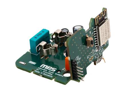
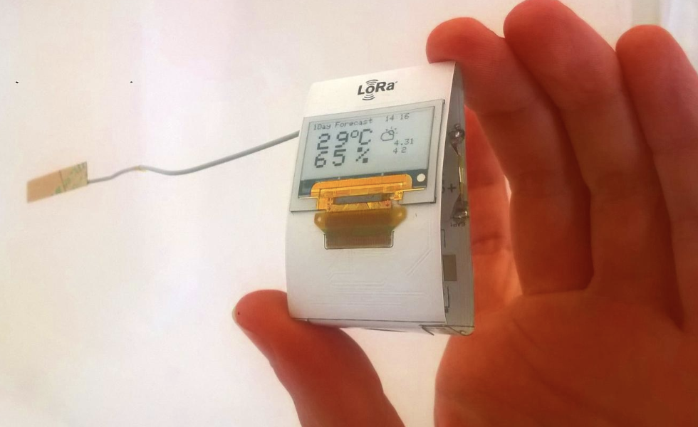
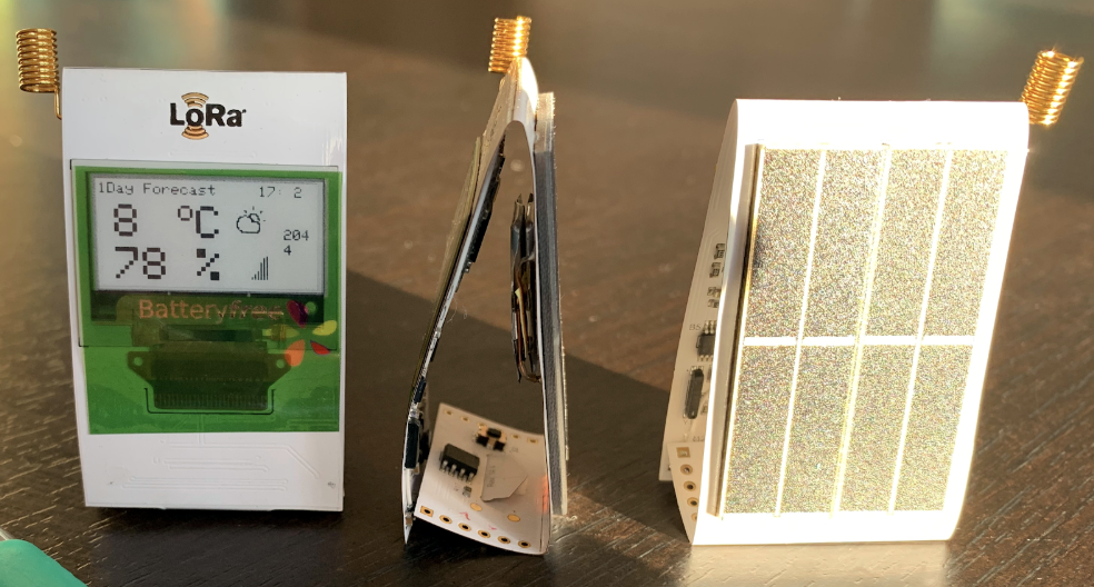
Robert Poser, passionate about ePaper displays and the famous creator of Paperino ( an easy-to-use, micro ePaper shield for the Particle & Arduino) has created LoraPaper, a LoraWan-connected ePaper display powered by only ambient light – this implies no batteries, at all, as it is entirely solar-powered through a PV cell on its back that constantly keeps an AEM10941 supercapacitor charged. Therefore, it runs autonomously when attached to the window or close to it.

LoraPaper’s display is sourced from Plastic Logic, a Hong Kong-based company that develops and manufactures truly flexible, glass-free electrophoretic displays for smart cards, mobile devices, signage, wearables e.t.c. Also, its charging is automated by an energy harvesting charge controller developed by E-peas semiconductors.

During the recently concluded The Things Conference, Robert showcased a 2.1-inch display version of the device (An upgraded version from the original 1.1-inch display) with a flexible lowlight PV cell on its backside. He noted that he is currently working on enabling support of external SPI flash for loading/saving images.

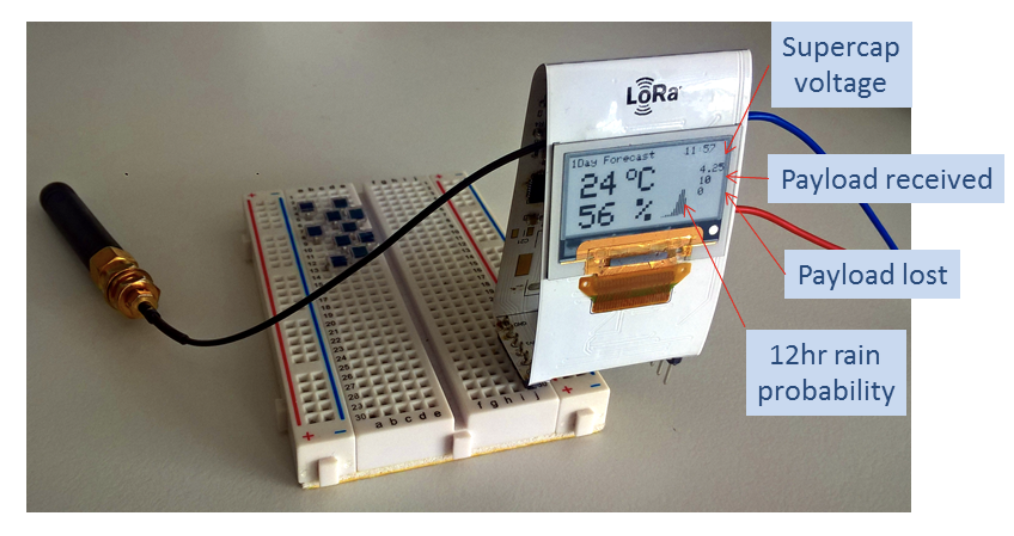
Depending on several conditions and the image content. It takes on average roughly 4mA at 3.3V for ~300ms to transition display, that is when the device connects to the web via The Things Network (TTN).

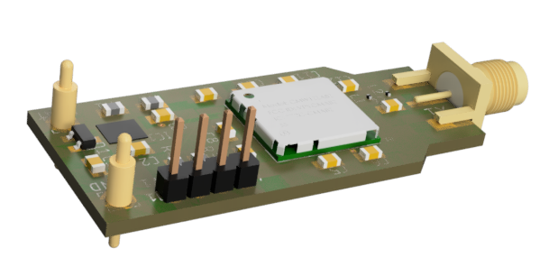
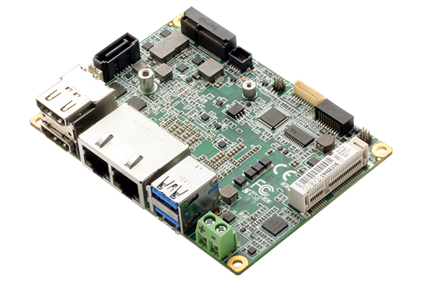
The LoraPaper is based on the Atmega328p microcontroller and as such, can be programmed with the Arduino IDE with help from it’s Arduino library which accounts for the slower clock speed nature of the LoRaPaper.

An FTTI programmer will be needed to program the LoraPaper through the pins exposed on the bottom side.

More information on the project along with the datasheet, schematics, and examples for LoraPaper can be found on it’s Github project page.

0 to 5V output Analog Hall Sensor for Foot Controller

This project includes an analog Hall Effect sensor and an Op-Amp circuit which can be used as position or angular sensing with the benefits of no contact and wearing, high stability and wide sensing range. Two configurations of the magnet and Hall sensors are analyzed. Trimmer Potentiometer PR2 provided to adjust the offset and PR1 helps to set the system gain. The Op-Amp circuit helps to achieve the desired output bias and range. The sensor provides an approximately linear response, adapt wide magnet types and field range. DRV5053 Sensor is the heart of the project. The DRV5053 device is a chopper-stabilized Hall IC that offers a magnetic sensing solution with superior sensitivity stability over temperature and integrated protection features.  The project is useful for applications like Foot Controller, Industrial control stick, Industrial foot pedal, general position or angular sensing.

0 to 5V output Analog Hall Sensor for Foot Controller – [Link]

ESP32 LoRa Sensor Monitoring with Web Server (Long Range Communication)

I’m a big fan of the ESP32 boards because of the number of communication options they managed to squeeze on the board, but I became more impressed recently when I came across the TTGO LoRa32 development boards which adds LoRa to the onboard communication features of the ESP32.

The LoRa communication capacity of the board opens up a web of possibilities and as a demonstration of how the board works, for today’s tutorial, we are going to build a LoRa Sensor Monitor with a webserver.

The idea behind the project is simple and not so different from the “Introduction to LoRa communication” project we built recently. It comprises two parts; a Transmitter and a Receiver. The transmitter comprises of a TTGO LoRa32 development board along with a BME280 sensor which is used to obtain temperature and humidity parameters from the environment. The data obtained are sent using the LoRa Communication features of the TTGO LoRa32, to the receiver which receives the data and displays it on a webpage via a webserver hosted on the board. By visiting the IP address of the server on any device on the same network as the receiver’s LoRa32 board, users will be able to see the data displayed on a webpage.

At the end of today’s project, you would know how to use both the WiFi and LoRa features of the TTGO LoRa32 board.

ESP32 LoRa Sensor Monitoring with Web Server (Long Range Communication) – [Link]

Smart Power Bank Keep-Alive

@ZakKemble published another interesting project. This time it is a USB device that aims to keep your power bank from powering down due to low current draw. He writes:

Ever wanted to power a project from a USB power bank, only to have it keep shutting itself off because the current draw was too low? This project aims to fix that with these handy and slightly over-engineered USB modules containing a microcontroller, op-amp, MOSFET and a few other bits to create a pulsed adjustable constant current sink, as well as supporting USB 3 pass-through!

A quick hack to keep power banks alive is to use something like a 150R resistor across the power output to draw an extra 33mA, but some power banks might need as much as 100mA to stay on, requiring a 50R 1W power resistor. Usually, power banks don’t need to have current continuously flowing to stay on, where a 2 second pulse every 15 seconds might be enough to keep it alive. This pulsing technique drastically improves the battery life of the power bank, perfect for powering a small project for a few weeks.

[…]

The smarts of this device is an ATtiny10 which controls the on and off cycling of the constant current sink (pulse duration and interval is adjustable via firmware). The current is adjustable via a small trim potentiometer from 0mA to 140mA and the supply voltage can be anywhere from 1.8V to 5.5V.

Designs and firmware are on his GitHub and he also sells it on Tindie.com

snopf is a Tiny USB password token

snopf is a very simple, yet effective and easy to use USB password tool. The snopf USB device creates a unique and strong password for every service from the same 128 bit secret which never leaves the token.

Whenever snopf is plugged into the computer you can make a password request and then the red LED will light up. If you press the button within 10 seconds snopf will imitate a keyboard and type the password for the requested service.

snopf is designed as a hardware-based password generator to tackle the security issues most commonly encountered with stored passwords on ordinary PCs, such as reading of password files by malware or browser exploits. It generates passwords deterministically from a securely kept master secret unaccessible to software running on the host.


Advantages of snopf

  • Very simple and robust design
  • Easy to use
  • You don’t have to remember any passwords anymore (except preferably a master PIN for snopf)
  • Every password is unique and as strong as the accessed service allows
  • The actual password creation is only happening on the USB device
  • It is possible to restore all passwords from a 12 word mnemonic representing the 128 bit secret
  • It’s more secure than a common pure software based password manager because the password creation is physically detached from the computer
  • As snopf emulates a regular keyboard, no passwords are stored in the clipboard

more details about the snopf project can be found on github.com

Batbot – the battery monitor that keeps you informed

A vehicle and leisure battery monitor that alerts you remotely on your phone when the battery is about to be discharged beyond use.

Batbot simply hooks up via two croc clips (provided) to the battery points under your vehicles bonet and can be secured in place with a cable tie.

Once installed the device then sends your battery’s data to the cloud where alerts are generated and then sent to your mobile device or email address. Unlike other products, Batbot uses the Sigfox or LoRaWAN radio networks to send this data, so no bluetooth connection is required.

You can choose which version of Batbot will work best for you, based on the coverage in your area. We’ll go into more detail on this a little later on…

Key Benefits of Batbot:

  • Quick and easy to use
  • Keeps track of your battery state
  • Alerts you when action is required
  • Saves destroying batteries with deep discharge
  • Regular daily “All Ok” status for peace of mind
  • No monthly SIM contract
  • First year subscription included
  • Low further yearly subscription (£7 ~ £10)
  • Chose Sigfox or LoRaWAN version of product
  • LoRaWAN has Home Gateway option to provide cover in remote areas
  • Helps identify when your battery or vehicle has an electrical fault.
  • Avoids the vehicle not starting when needed for emergency or planned use
  • Save’s garage call out charges to jump start your vehicle
  •  24V lorries can be difficult to find a suitable jump start source for, or require a garage call out. Batbot helps you avoid this problem

Features:

  • Detects when your battery is discharging to a “beyond use” state and allows you to take corrective action, for example by starting the engine.
  • Supports 6V, 12V and 24V Battery Systems.
  • Comes with Croc Clips or Ring Terminals as a connection methods. (Accessory Pack provides further options).
  • Daily ‘All Good’ status, provides peace of mind that the vehicle is still in a good condition.

The project is live on kickstarter and had 24 days to go.

PICO-WHU4: Compact Board Built for the Edge

AAEON, an industry leader in embedded AI Edge solutions, announces the PICO-WHU4, the latest compact board designed for embedded artificial intelligence, and edge computing. Built on the PICO-ITX form factor and powered by 8th Generation Intel® Core™ Processors, the PICO-WHU4 is a powerful and compact solution for a wide range of applications.

The PICO-WHU4 is built to offer high performance computing in a compact size. It features the 8th Generation Intel® Core™ i3/i5/i7 and Celeron® processors (formerly Whiskey Lake) combined with support for up to 16 GB of DDR4 RAM. This setup provides an impressive level of computing performance on the compact PICO-ITX form factor, allowing the PICO-WHU4 to power many AI and edge computing applications. With a wide operating temperature range from 0°C to 60°C, the PICO-WHU4 is a tough and reliable system for any working condition.

Built to meet the ever-growing demands for embedded AI and Edge Computing, the PICO-WHU4 offers an I/O configuration designed to integrate with almost any embedded application. The PICO-WHU4 features two Ethernet ports, two HDMI ports, and four USB 3.2 Gen 2 ports. The board also features two COM headers, supporting RS-232/422/485 serial port operation.

The PICO-WHU4 is also easy to expand, with an M.2 slot providing support for Wi-Fi and Bluetooth connectivity, and a mSATA/mPCIe slot which can support expansions such as the AI Core X with Intel® Movidius® Myriad™ X. Manufacturer Support from AAEON can also custom configure the PICO-WHU4 to suit customer projects, helping to reduce development time and time-to-market.

The PICO-WHU4 is also available as a turn-key solution, the PICO-WHU4-SEMI compact embedded system. With a compact chassis, the PICO-WHU4-SEMI is built to provide customers a complete system solution which is easy to setup and deploy.

“The PICO-WHU4 is a powerful solution that’s built for the edge,” said Kevin Chiu, Head of AAEON’s Embedded Computing Division. “With compact size and Intel® Core™ processors, the PICO-WHU4 is the perfect solution for vertical markets including Smart Retail applications and Smart City infrastructure.”

more information: www.aaeon.com

Toshiba launches new high-resolution micro-stepping motor driver IC with integrated current sensing

Toshiba Electronics Europe GmbH has launched an additional device to its line-up of micro-stepping motor driver ICs. The new TC78H670FTG is a dual channel high resolution micro-stepping motor driver IC that is capable of driving motors with a wide range of operating voltages. The new device is intended for a broad variety of consumer applications including 3D printers, cameras, security cameras, portable printers, handheld scanners, pico-projectors and battery powered medical devices.

The IC can drive a micro-stepping motor of up to 128 steps and with a voltage ranging from 2.5 V to 16 V at currents of up to 2 A. The output on-resistance (RDS(ON)) is only 0.48Ω as the TC78H670FTG uses Toshiba’s latest CDMOS process, thereby reducing voltage loss and heat generation inside the driver.  An ultra-low standby current of just 0.1 µA prolongs battery life and the ability to operate with a 1.8 V to 5.0 V interface allows connection to a wide variety of hosts and microcontrollers. As a result, the device is suited for use in USB powered and battery powered applications as well as with standard 9-12V system devices.

Summary of Features

  • Built-in Dual H Bridges, Capable of controlling 1 bipolar stepping motor
  • PWM controlled constant-current drive
  • Power supply operating voltage: 2.5V to 16.0V
  • Output current ratings: 2.0A (max)
  • Low on-resistance (High + Low side = 0.48Ω (typ.)) MOSFET output stage
  • Allows full, half, quarter, 1/8, 1/16, 1/32, 1/64, 1/128 step operation
  • Built-in Sense resistor less current control architecture (Advanced Current Detection System)
  • Multi error detect functions (Thermal shutdown (TSD), Over current (ISD), motor load open (OPD) and Under voltage lockout (UVLO))
  • Error detection (TSD/ISD/OPD) flag output function
  • Built-in VCC regulator for internal circuit
  • Chopping frequency of a motor can be adjusted by external resistor
  • Small QFN package with thermal pad (16-pin)
  • Ultra-low standby current of 0.1mA
  • Operates motors smoothly and quietly and reduces vibration; improved rotation angle accuracy achieved by micro-stepping control.

Internal Diagram

The micro-stepping control allows motors to be operated smoothly and quietly with reduced vibration and improved rotation angle accuracy. Safety features such as over current detection, thermal shut down and open-load detection are incorporated. The sophisticated motor driver is housed in a compact QFN16 package with a footprint of just 3 mm x 3 mm which, along with the elimination of the two bulky and expensive current sense resistors by incorporating on-chip current detection, contributes to significant cost and space saving in designs.

more information: toshiba.semicon-storage.com

0 to 5V output Analog Hall Sensor for Foot Controller

This project includes an analog Hall Effect sensor and an Op-Amp circuit which can be used as position or angular sensing with the benefits of no contact and wearing, high stability and wide sensing range. Two configurations of the magnet and Hall sensors are analyzed. Trimmer Potentiometer PR2 provided to adjust the offset and PR1 helps to set the system gain. The Op-Amp circuit helps to achieve the desired output bias and range. The sensor provides an approximately linear response, adapt wide magnet types and field range. DRV5053 Sensor is the heart of the project. The DRV5053 device is a chopper-stabilized Hall IC that offers a magnetic sensing solution with superior sensitivity stability over temperature and integrated protection features.  The project is useful for applications like Foot Controller, Industrial control stick, Industrial foot pedal, general position or angular sensing.

The output of DRV5053 is about 0.2V to 1.8V with the quiescent 1V at zero fields or no perpendicular flux to the sensing surface. In the non-linear configuration, the output range is limited either from 0.2V to 1V or from 1V to 1.8V. An Op-Amp stage is introduced in this design. It deals with the raw Hall sensor output signal with adjustable offset and scaling range. LMV612 op-amp used for signal conditioning. Actually, any fixed position along the full stroke of the magnet can be set as an offset point mechanically. When the relative position of the magnet and the Hall sensor is fixed at the designed offset point, the final output voltage can be adjustment by PR2. U1B is used as the amplitude amplifier stage with adjustable gain tuning by PR1. Also, there is an RC filter at the final output with R3 and C4.  The actuator is fixed at a mid-point between the two ends of the stroke by a dual-spring system. Controlling by the foot, the actuator can go two sides of the stroke direction. The application requires the output to stay at about 1.1V when the actuator is at a balanced point (fixed offset point). When the foot strokes downside, the output goes from 1.1V down to ~0V. When the foot strokes upside, the output goes from 1.1V up to ~5V.

Features

  • Supply 5V DC
  • Approximate linear response
  • Adapt to wide magnet types and field range
  • 0 to 5V full scale output ability
  • Adjustable quiescent offset and gain
  • Low power RRIO amplifier stage
  • Cost-effective
  • PCB Dimensions 32.09mm X 12.70MM

Tuning Guide

  1. Tuning PR2 for the designed fixed offset output
  2. Place the magnet to its MIN MAX stroke and tuning PR1 to get designed output range
  3. Release or return the fixed offset point, back to step 1 readjustment the offset point
  4. Back to step 2 to readjustment the offset output
  5. Repeat 1 to 4 steps to get both the designed offset the scaled output range.
  6. Note that the adjustment range of offset and scaling is also related to the mechanical magnet Configuration and the magnetic field. Do possible adjustment of the mechanical configuration if needed.
  7. The OpAmp parameters are also adjustable for special sensing range and output coverage. It is recommended to change R1 for extend offset adjustment ability and R8 for extend the gain range.

Schematic

Parts List

Connections

Mechanical Drawing

Magnet Position vs Output

Photos

DRV5053 Datahseet

Smart Plug Reference Design – MP161 Non-Isolated Buck Regulator with ESP8266

Nowadays everything is connected. So why not also connect the wall plugs? Monolithic Power Systems presents a reference design with the MP161 part that will allow customers to join the IoT market. This is a two boards design, one for the dc-dc converter and the relay and the other for the Wi-Fi module. The configuration is designed to fit into a wall-plug.

This reference design is based on the MP161 which includes a 700V switching regulator, a low-dropout linear regulator and two channel relay drivers. The design includes Wi-Fi 802.11 b/g/n (HT20) protocol and 35.4mW active input power under stand-by operation.

Smart plug block diagram.

The relay driver in the MP161 includes 2Ω on-state resistance, rail voltage up to 30V, integrated freewheeling diode, and a nominal off driver. The integrated LDO handles up to 30V input voltage; it delivers a fixed output of either 3.3V or 5V and includes over-temperature protection

Summary of MP161 Features

  • Integrated 700V MOSFET and current source
  • Constant voltage regulation with internal loop compensation
  • Optimized light-load efficiency by frequency modulation
  • Standby mode
  • Anti-audible noise operation by peak current modulation
  • Adjustable or fixed 12V Output
  • Low operating current
  • Integrated protection functions
    • Over-Temperature Protection (OTP)
    • Short-Circuit Protection (SCP)
    • Over-Load Protection (OLP)
    • Over-Voltage Protection (OVP)
more details: www.monolithicpower.com
TOP PCB Companies