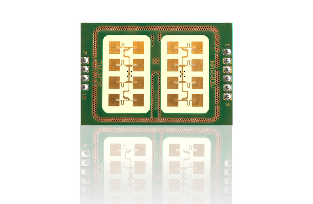
InnoSenT’s IPS-354 operates in the 24 GHz ISM band and was developed for classic industrial radar applications, especially as a motion sensor for escalators. It is a K-band transceiver with two antennas; the split of the transmitting and receiving path enables maximum gain. For signal intensification, it also comes with an IF pre-amplifier. Its bandwidth is limited to lower the noise floor. Because of its stability in frequency, one version is usable for worldwide use. This product is also available with a wider beam by the manufacturer directly.
The IPS-354 detects the velocity and direction of moving objects in a mid-range coverage area and offers detection range up to 30 meters. The sensor uses a stereo (dual-channel) operation for the identification of motion direction.
To get information about the distance and presence of objects, an FMCW version of the IPS-354 is also available. The IVS-362 detects moving and stationary objects and recognizes distance.
Features
24 GHz ISM band
K-band transceiver
Analog radar
Split transmit and receive path for maximum gain
IF-pre-amplifier
Bandwidth-limited for lowest noise performance
Stereo (dual-channel) operation
CW-radar module
Motion detection
Velocity measurement
Direction detection
Mid-range detection area
Certified and approved according to FCC rule 15C, RED article 3.2
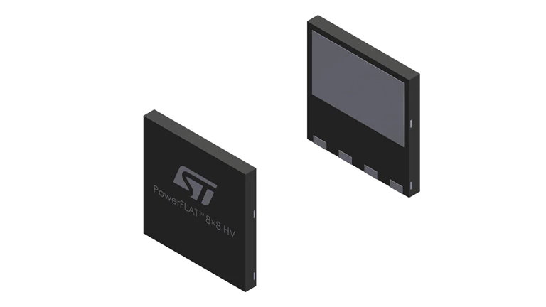
STPSC8H065 – 650 V, 8 A high surge silicon carbide power Schottky diode
This 8 A, 650 V SiC diode is an ultrahigh performance power Schottky diode. It is manufactured using a silicon carbide substrate. The wide band gap material allows the design of a Schottky diode structure with a 650 V rating. Due to the Schottky construction, no recovery is shown at turn-off and ringing patterns are negligible. The minimal capacitive turn-off behavior is independent of temperature.
The STPSC8H065 is especially suited for use in PFC applications. This ST SiC diode will boost the performance in hard switching conditions. Its high forward surge capability ensures a good robustness during transient phases.
Key features
No reverse recovery charge in application current range
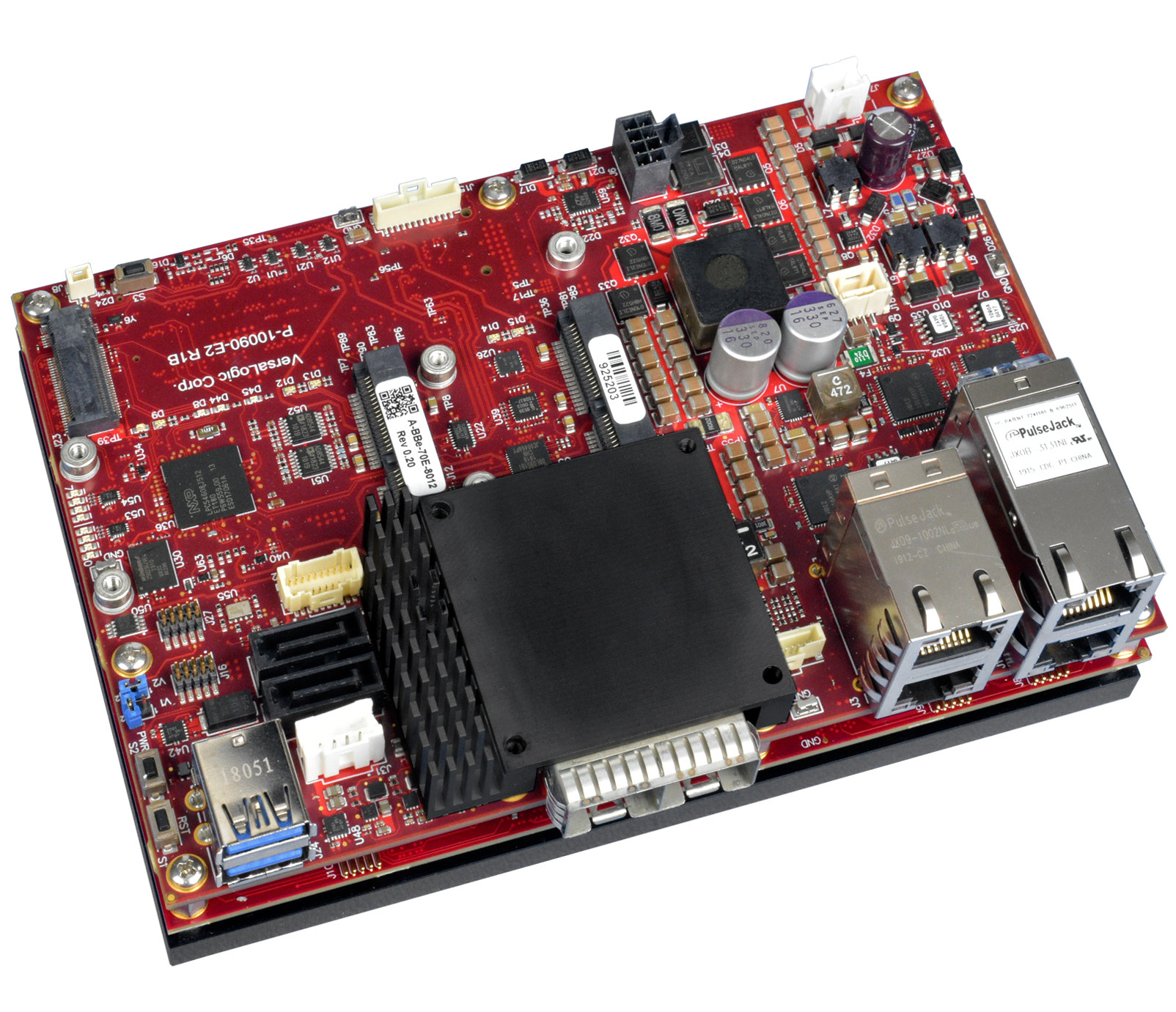
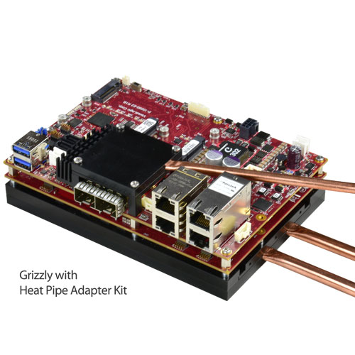
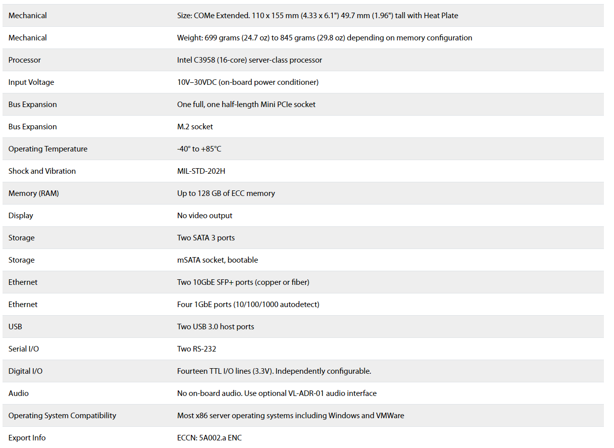
A rugged embedded server featuring an Intel 16-core processor, -40°C to +85°C operation, two 10 Gigabit Ethernet SFP+ ports, and up to 128 GB of ECC memory. It is ideal for high performance/high data bandwidth applications. Two Mini PCIe sockets and an M.2 site provide for expansion and on-board storage.
The Grizzly is a rugged embedded server unit (ESU) featuring an Intel 16-core processor, full -40°C to +85°C operation, two 10 Gigabit Ethernet SFP+ ports, four Gigabit Ethernet ports, up to 128 GB of ECC memory and Intelligent Platform Management Interface (IPMI 2.0) functionality. This combination makes it ideal for edge server and HPEC applications requiring very high-performance processing and high data bandwidth. Additionally, two Mini PCIe sockets and a PCIe x4 M.2 site provide for on-board I/O expansion and high speed / high-capacity on-board storage. The Grizzly also contains additional interfaces including USB, serial and digital I/O, and SATA.
The high-performance capability of the Grizzly makes it ideal for situations where data gathering and processing need to be kept local for security or latency reasons, or to provide local cloud capability. A 16-core processor coupled with up to 128 GB of ECC memory supports the use of hypervisors for running of virtual machines. The 10 Gigabit SFP+ ports permit very high speed connectivity. Networks can be created using plug-in copper, short-reach fiber, or long-reach fiber transceivers.
The Grizzly is based on the COM Express Extended form-factor, but it is delivered as an assembled and tested, production-ready embedded computer. For hostile environments, the Grizzly is designed and tested for full industrial temperature operation (-40° to +85°C) and meets MIL-STD-202H specifications for shock and vibration.
VersaLogic’s 10+ year product life support ensures long-term availability. This avoids expensive upgrades, redesigns, and migrations that come from shorter lifecycle products.
Features:
Embedded server
Intel® 16-core server-class processor and IPMI 2.0 capability
-40°C to +85°C Operation
Operates over full industrial temperature range
128 GB of ECC memory
Industry leading capacity and error correcting RAM
10 Gigabit Ethernet (SFP+)
Supports two high speed copper or fiber connections
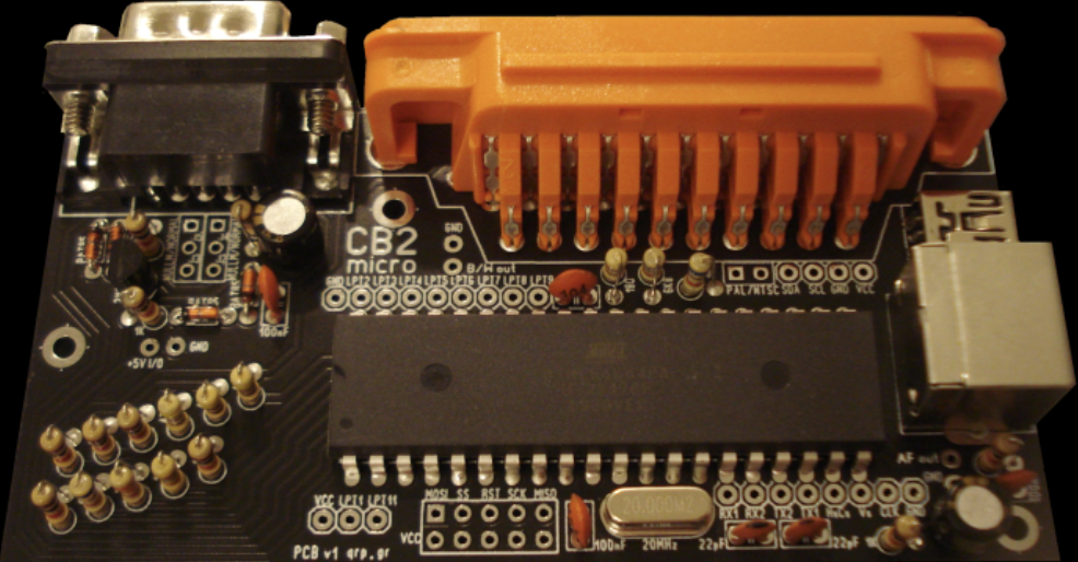
If you’d like to return to a time when your computer had very accessible components, a microprocessor, RAM, ROM, and I/O chips all hanging from an exposed bus, you can do so by building your very own BASIC color microcomputer with the CB2 micro kit in under 30 minutes for as low as ~$28.
The kit was designed to be plain simple and very affordable being tailored to those who don’t have access to regular retro computers but would want to have fun with these types of technologies or even learn and experiment with BASIC.
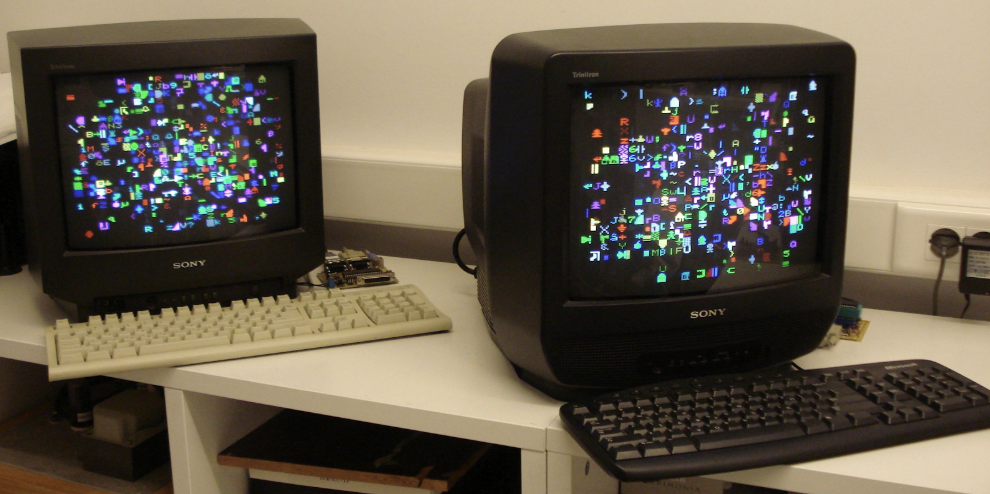
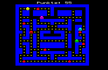
CB2 is very easy to assemble, it works like the micros from the ‘80s except it is cheaper and much easier to use. It works directly with a TV and keyboard, no PC’s required, and it can be used as a standalone microcomputer to run games and applications. It can also be used for automation processes without using a monitor or keyboard and even as a measurement instrument for hobbyists.
CB2’s firmware is based on an open-source project built by Joerg Wolfram (called AVR ChipBasic2). It utilizes standard interfaces such as RS-232, UART, LPT, I2C, etc. to communicate with devices like control modems with an ATmega644P chip (ATMEGA644P-20PU or ATMEGA644PA-PU), which connects up to a PS2 keyboard port, as well as a 9-pin connector for serial operations.
The CB2 micro has SCART (RGB) video and B&W composite right out of the box. There’s no need for extra adapters, except when you need color composite – that’s possibly the only scenario when you’ll need an adapter to build. The signals for this color composite adapter are taken from the RGB of the SCART pins and the Hsync/Vsync on the PCB. There is no special Dsub connector in the CB2 micro.
Some interesting features of the kit include:
16 foreground and background colors (PAL/NTSC) on TV SCART (RGB/Hsync/Vsync), pseudographics and B/W composite. Color composite/HDMI/VGA support with external converters.
Sound with envelope and volume adjustment.
PS/2 keyboard (or USB with adapter), RS232, 2x serial TTL, LPT, 8x A/D inputs and I2C, all BASIC controlled.
Tiny-BASIC with a featured embedded editor, Chip8, SCHIP, 8080 and AVR-native binaries supported.
Cross programs call external flash and EEPROM options.
The terminal program, color terminal, X-modem transfer, PC connectivity, networking.
The kit comes with eight programs stored on the internal flash. More information along with various applications or hardware extensions for CB2 micro is available here.
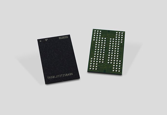
New generation 3D flash memory adds layers, boosts capacity, broader bandwidth and provides new design flexibility
KIOXIA Europe GmbH, the world leader in memory solutions, today announced that it has successfully developed its fifth-generation BiCS FLASH three-dimensional (3D) flash memory with a 112-layer vertically stacked structure. KIOXIA plans to start shipping samples of the new device, which has a 512 gigabit (64 gigabytes) capacity with 3-bit-per-cell (triple-level cell, TLC) technology, for specific applications in the first quarter of the calendar year 2020[1].
The new device aims to fulfill ever-growing bit demands for a wide variety of applications, including traditional mobile devices, consumer and enterprise SSDs, emerging applications enabled by the new 5G networks, artificial intelligence and autonomous vehicles.
Going forward, KIOXIA will apply its new fifth-generation process technology to larger capacity devices, such as 1 terabit (128 gigabytes) TLC and 1.33 terabit 4-bit-per-cell (quadruple-level cell, QLC) devices.
KIOXIA’s innovative 112-layer stacking process technology is combined with advanced circuit and manufacturing process technology to increase cell array density by approximately 20 percent over the 96-layer stacking process. The new technology reduces the cost per bit and increases the manufacturability of memory capacity per silicon wafer. Additionally, it improves interface speed by 50 percent and offers higher programming performance and shorter read latency.
Since announcing the world’s first[2] prototype 3D flash memory technology in 2007, KIOXIA has continued to advance the development of 3D flash memory and is actively promoting BiCS FLASH to meet the demand for larger capacities with smaller die sizes.
Fifth-generation BiCS FLASH was developed jointly with technology and manufacturing partner Western Digital Corporation. It will be manufactured at KIOXIA’s Yokkaichi Plant and the newly built Kitakami Plant.
[1] Not all features have been tested and device characteristics may change in the future.
[2] Source: KIOXIA Corporation, as of June 12, 2007.
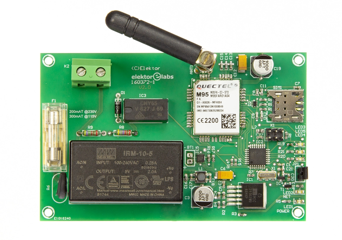
Power outages are fairly rare in central Europe, and when they do occur, they are usually short. However, if the heating system of your holiday home doesn’t start up again after a power outage, the consequences can be costly. And even if only your freezer at home stops working while you’re on holiday, the stench when you get back can spoil your homecoming. The detector described here detects even short power outages and sends you text message alerts. Note: For 115-VAC operation replace R9 by a wire strap.
Original publication: Elektor Magazine 4/2018 on page 12
Authors: Luc Lemmens Mathias Claussen
Free download expires: Friday 14 February 2020.
Original article production number: 160372
Software, Bare PCB, Semi-kit available; see PRODUCTS below. Semi-kit available at a discounted price.
Like what you’re seeing? Then go to the article page and download a pdf copy of the full, original article from 2018. Downloading is free from Friday 7 February to Friday 14 February 2020.
Special Offer: the semi-kit of the Power Outage Detector is available at a discounted price. Click on the PRODUCT below. Offer is limited to stocks. The bare PCB and the ready-programmed microcontroller for the project are also available.
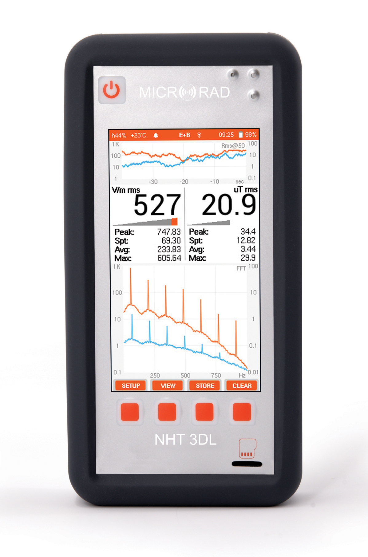
Microrad’s NHT 3DL Electromagnetic Field Analyzer is designed to measure electromagnetic fields in both time and frequency domains and in compliance with all the main international standards and regulations
Saelig Company, Inc. has introduced the Microrad NHT 3DL Electromagnetic Field Analyzer, which is designed to measure electromagnetic fields in both time and frequency domains and in compliance with all the main international standards and regulations. A wide selection of interchangeable electromagnetic field probes allows this handheld analyzer to measure complex electric and magnetic fields from DC to 1MHz in Selective Mode, and 0 to 40GHz in Wideband Mode. The Monitoring Mode function allows for received signals from the attached probe to be recorded to the instrument’s non-volatile internal memory. The NHT 3DL can analyze and store complex waveforms with transitory and pulse characteristics. This saved data can then be downloaded to a PC in order to extract relevant information acquired during the monitoring. Battery power allows the user to perform monitoring tasks for at least 24 hours. NHT 3DL can be entirely controlled remotely via fiber optic or wireless (Wi-Fi) connections. Outdoor monitoring in all weather conditions can be carried out, due to the NHT 3DL’s IP67 enclosure.
The NHT 3DL when operating in broadband mode with E series probes covers frequencies from 100kHz to 40GHz. When utilized in conjunction with the ER series probes it can demodulate and rebuild radar signal pulses up to 500ns, providing automatic measurement of Tau, PRF and Duty Cycle values. This mode is particularly useful for radar source recognition and measurement. In the FFT Analysis Mode, the device covers the 1MHz band in four decades, 1/10/100/1,000kHz with 1,000 points resolution per decade and automatic peak search markers. In the Oscilloscope Mode, it displays high-definition time frames with manual trigger function and Amplitude/Time marker. The NHT 3DL, when combined with the new 33S Triple Probe, can measure static magnetic, magnetic, and electric fields from 1Hz to 1MHz in a disjoint/combined mode.
The operator interface is based on a high-resolution color touch screen display. It can be remotely controlled via Wi-Fi or fiber-optic connection, with the display shown on Windows and Android devices. The Microrad NHT 3DL analyzer is designed to operate also as an area monitor.
The NHT 3DL is ready for the 5G challenge, for the automotive/railway electric traction industry, the medical diagnostics field, or wherever regulated industrial activities exist. The NHT 3DL’s 5G Trigger function is capable of capturing events up to 100 microseconds. 5G utilizes mobile directional beams (Full Dimensional 3D) with the possibility of directing the radiated lobe of the antenna in a targeted way towards the individual user, even in motion. The mobile directional beams, in horizontal plane (azimuth) as well as in vertical plane (elevation), are emitted from macro-cellular, micro-cellular and pico-cellular sites that use Massive MIMO (Multiple Input Multiple Output) antennas up to 8×8 elements. 5G is a system that optimizes the electromagnetic coverage both in spatial and energetic terms, able to modify the dimensional characteristics of the radiation beam both in Beam Sweeping and in Beam Tracking phases.
Made by Microrad, a recognized leader in electromagnetic safety instrumentation, the NHT 3DL Electromagnetic Field Analyzer is available now from Saelig Company, Inc. their USA technical distributor.
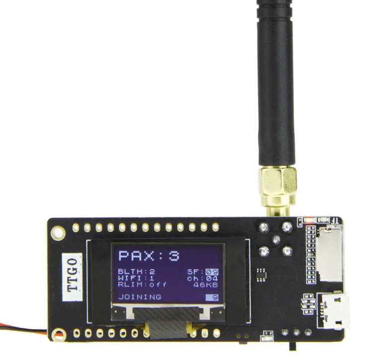
I’m a big fan of the ESP32 boards because of the number of communication options they managed to squeeze on the board, but I became more impressed recently when I came across the TTGO LoRa32 development boards which adds LoRa to the onboard communication features of the ESP32.
TTGO LoRa 32 Development Board
The LoRa communication capacity of the board opens up a web of possibilities and as a demonstration of how the board works, for today’s tutorial, we are going to build a LoRa Sensor Monitor with a webserver.
The idea behind the project is simple and not so different from the “Introduction to LoRa communication” project we built recently. It comprises two parts; a Transmitter and a Receiver. The transmitter comprises of a TTGO LoRa32 development board along with a BME280 sensor which is used to obtain temperature and humidity parameters from the environment. The data obtained are sent using the LoRa Communication features of the TTGO LoRa32, to the receiver which receives the data and displays it on a webpage via a webserver hosted on the board. By visiting the IP address of the server on any device on the same network as the receiver’s LoRa32 board, users will be able to see the data displayed on a webpage.
At the end of today’s project, you would know how to use both the WiFi and LoRa features of the TTGO LoRa32 board.
Required Components
The following components are required to build this project;
All components can be bought via the attached links. The battery is useful if you plan to use the project without being tethered to your PC by USB Cables.
Schematics
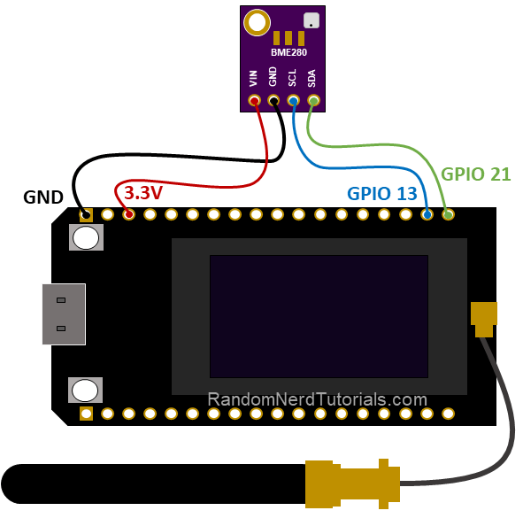
Even though the project involves two devices (transmitter and receiver), we will create schematics for just the transmitter since the TTGO LoRa32 board has everything we need for the receiver, onboard. For the transmitter, the BME280 communicates with connected microcontrollers over I2C, as such, all we need do is connect it to the I2C pins of the TTGO LoRa32 as shown in the image below:
A pin-to-pin connection of the components is described below;
BME280 – LoRa32
GND - GND
VCC - 3.3V
SCL - GPIO13
SDA - GPIO21
The connections when complete should look like the image below
Setting up the Arduino IDE
The code for today’s project will be developed using the Arduino IDE, we need to install two major support package; the ESP32 Board support package, and the ESP32 files system uploader, on it.
The ESP32 board support package provides all you need to program most ESP32-based boards with the Arduino IDE, while the ESP32 file system uploader allows access to the ESP32’s Serial Peripheral Interface Flash File System (SPIFFS). SPIFFS is a lightweight filesystem for microcontrollers that lets you access the flash memory like you would a normal filesystem on your computer. The ESP32 file uploader serves as a tool through which you can upload things like config files, or webserver files like we will be doing today, to the ESP32 SPIFFS. So instead of writing the HTML code for the webserver as a String directly on the Arduino sketch, we can write the HTML and CSS in a separate file and save them on the ESP32 filesystem.
The installation process for the ESP32 board support package has been covered in one of our past tutorials here, as such, for today’s tutorial our focus will be on the ESP32 Filesystem Uploader.
Installing the ESP32 Filesystem Uploader
To install the ESP32 filesystem uploader, it is required that you have the latest version of the Arduino IDE installed, along with the ESP32 board support for the IDE. With those in place, follow the steps below to install the file system uploader.
1. Download the File system uploader from the ESP32FS-1.0.zip release page.
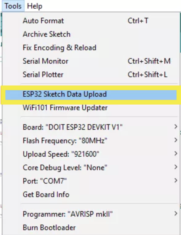
2. Go to the Arduino IDE directory, and open the Tools folder.
3. Unzip the downloaded .zip folder to the Tools folder. You should have a similar folder structure: <home_dir>/Arduino-<version>/tools/ESP32FS/tool/esp32fs.jar
4. With this done, restart the Arduino IDE and Check under tools you should see the ESP32 Sketch Data Upload options there as shown below.
Code
There are two sides to today’s project, as such, we will develop two sketches; one for the transmitter and one for the receiver. These sketches are unedited versions of the one used in Randomnerds tutorial‘s article.
Transmitter Sketch
The algorithm behind the transmitter is straight forward and similar to what we did in the “Introduction to LoRa” project. We obtain temperature and humidity data from the environment via the BME280, display it using the OLED on the TTGO LoRa32 and send it out to the receiver using LoRa communication features of the board.
To achieve this with ease, we will use five important libraries including: the Arduino LoRa library by Sandeep Mistry, the Adafruit SSD1306 library, the Adafruit_GFX library, the Adafruit_BME280 library, and the Adafruit unified sensor library. The Adafruit BME280 and Unified Sensor libraries are involved in reliably obtaining temperature and humidity information from the BME280, the Adafruit SSD1306 and GFX libraries are used in interaction with the OLED, and the Arduino LoRa library handles everything involved with sending the data to the receiver over LoRa. All five libraries can be installed via the Arduino IDE’s Library manager or by downloading them via the links attached to their names and installing them manually.
As usual, I will do a quick breakdown of the code with the aim of explaining parts that may be slightly difficult to follow. The code starts, as always, with the include statement for all the libraries that will be used.
//Libraries for LoRa
#include <SPI.h>
#include <LoRa.h>

//Libraries for OLED Display
#include <Wire.h>
#include <Adafruit_GFX.h>
#include <Adafruit_SSD1306.h>

//Libraries for BME280
#include <Adafruit_Sensor.h>
#include <Adafruit_BME280.h>
Next, the pins of the TTGO LoRa32 being used by the onboard LoRa module are specified;
//define the pins used by the LoRa transceiver module
#define SCK 5
#define MISO 19
#define MOSI 27
#define SS 18
#define RST 14
#define DIO0 26
This is followed by a declaration of the module’s frequency and a declaration of the pins of the TTGO LoRa32 being used by the OLED along with the display’s dimension.
//433E6 for Asia
//866E6 for Europe
//915E6 for North America
#define BAND 866E6

//OLED pins
#define OLED_SDA 4
#define OLED_SCL 15
#define OLED_RST 16
#define SCREEN_WIDTH 128 // OLED display width, in pixels
#define SCREEN_HEIGHT 64 // OLED display height, in pixels
It is important that you ensure the frequency of your LoRa module is, by law, allowed for use in projects like this.
Next, we declare the pins of the TTGO LoRa32 to which the BME is connected, and create an instance of the BME library.
Next, we create a counter variable to serve as an ID for messages, and a few more variables to hold the LoRa message, temperature, humidity, and pressure.
int readingID = 0;
int counter = 0;
String LoRaMessage = "";
float temperature = 0;
float humidity = 0;
float pressure = 0;
We round up this section by creating an instance of the OLED library with the OLED dimensions as arguments.
Next, we create a few functions which will be used later in the code. The functions include; the StartOLED() function which is used in initializing the OLED, the startloRA() function which is used in initializing and setting parameters for LoRa Communication, the StartBME() function which is used to initialize the BME280, the getReadings() function which is used to obtain temperature, humidity and pressure values from the BME280. and the void sendReadings() function which is used in sending the data obtained with the getReadings() function, over LoRa and also display it on the OLED.
The creation of the functions above helps reduce the amount of code required under the void setup() function. All we need to do is to initialize the serial communication so the serial monitor can be used for debugging purposes and call the initialization functions that were created above.
Next is the void loop() function. Just like we did under the void setup() function, all we have to do is call the required functions, which include the getReading() and sendReadings() functions. A delay of 10000ms was also added to allow ample time for sensor refresh.
The complete transmitter sketch is provided below and attached under the download section.
/*********
Rui Santos
Complete project details at https://RandomNerdTutorials.com/esp32-lora-sensor-web-server/
Permission is hereby granted, free of charge, to any person obtaining a copy
of this software and associated documentation files.
The above copyright notice and this permission notice shall be included in all
copies or substantial portions of the Software.
*********/
//Libraries for LoRa
#include <SPI.h>
#include <LoRa.h>
//Libraries for OLED Display
#include <Wire.h>
#include <Adafruit_GFX.h>
#include <Adafruit_SSD1306.h>
//Libraries for BME280
#include <Adafruit_Sensor.h>
#include <Adafruit_BME280.h>
//define the pins used by the LoRa transceiver module
#define SCK 5
#define MISO 19
#define MOSI 27
#define SS 18
#define RST 14
#define DIO0 26
//433E6 for Asia
//866E6 for Europe
//915E6 for North America
#define BAND 866E6
//OLED pins
#define OLED_SDA 4
#define OLED_SCL 15
#define OLED_RST 16
#define SCREEN_WIDTH 128 // OLED display width, in pixels
#define SCREEN_HEIGHT 64 // OLED display height, in pixels
//BME280 definition
#define SDA 21
#define SCL 13

TwoWire I2Cone = TwoWire(1);
Adafruit_BME280 bme;
//packet counter
int readingID = 0;

int counter = 0;
String LoRaMessage = "";

float temperature = 0;
float humidity = 0;
float pressure = 0;
Adafruit_SSD1306 display(SCREEN_WIDTH, SCREEN_HEIGHT, &Wire, OLED_RST);
//Initialize OLED display
void startOLED(){
  //reset OLED display via software
  pinMode(OLED_RST, OUTPUT);
  digitalWrite(OLED_RST, LOW);
  delay(20);
  digitalWrite(OLED_RST, HIGH);

  //initialize OLED
  Wire.begin(OLED_SDA, OLED_SCL);
  if(!display.begin(SSD1306_SWITCHCAPVCC, 0x3c, false, false)) { // Address 0x3C for 128x32
    Serial.println(F("SSD1306 allocation failed"));
    for(;;); // Don't proceed, loop forever
  }
  display.clearDisplay();
  display.setTextColor(WHITE);
  display.setTextSize(1);
  display.setCursor(0,0);
  display.print("LORA SENDER");
}

//Initialize LoRa module
void startLoRA(){
  //SPI LoRa pins
  SPI.begin(SCK, MISO, MOSI, SS);
  //setup LoRa transceiver module
  LoRa.setPins(SS, RST, DIO0);

  while (!LoRa.begin(BAND) && counter < 10) {
    Serial.print(".");
    counter++;
    delay(500);
  }
  if (counter == 10) {
    // Increment readingID on every new reading
    readingID++;
    Serial.println("Starting LoRa failed!");
  }
  Serial.println("LoRa Initialization OK!");
  display.setCursor(0,10);
  display.clearDisplay();
  display.print("LoRa Initializing OK!");
  display.display();
  delay(2000);
}

void startBME(){
  I2Cone.begin(SDA, SCL, 100000);
  bool status1 = bme.begin(0x76, &I2Cone);
  if (!status1) {
    Serial.println("Could not find a valid BME280_1 sensor, check wiring!");
    while (1);
  }
}

void getReadings(){
  temperature = bme.readTemperature();
  humidity = bme.readHumidity();
  pressure = bme.readPressure() / 100.0F;
}

void sendReadings() {
  LoRaMessage = String(readingID) + "/" + String(temperature) + "&" + String(humidity) + "#" + String(pressure);
  //Send LoRa packet to receiver
  LoRa.beginPacket();
  LoRa.print(LoRaMessage);
  LoRa.endPacket();

  display.clearDisplay();
  display.setCursor(0,0);
  display.setTextSize(1);
  display.print("LoRa packet sent!");
  display.setCursor(0,20);
  display.print("Temperature:");
  display.setCursor(72,20);
  display.print(temperature);
  display.setCursor(0,30);
  display.print("Humidity:");
  display.setCursor(54,30);
  display.print(humidity);
  display.setCursor(0,40);
  display.print("Pressure:");
  display.setCursor(54,40);
  display.print(pressure);
  display.setCursor(0,50);
  display.print("Reading ID:");
  display.setCursor(66,50);
  display.print(readingID);
  display.display();
  Serial.print("Sending packet: ");
  Serial.println(readingID);
  readingID++;
}
void setup() {
  //initialize Serial Monitor
  Serial.begin(115200);
  startOLED();
  startBME();
  startLoRA();
}
void loop() {
  getReadings();
  sendReadings();
  delay(10000);
}
Receiver Code
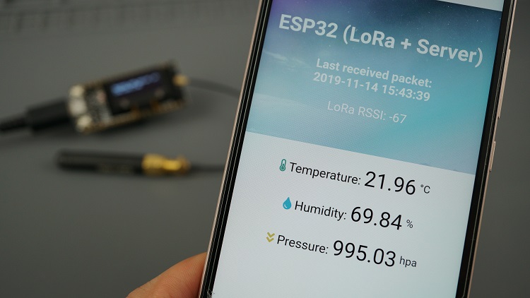
The receiver, as mentioned earlier, receives temperature and humidity values from the transmitter and displays it, along with the time it was received and the signal strength(RSSI), on a webpage hosted on the TTGO LoRa32 board.
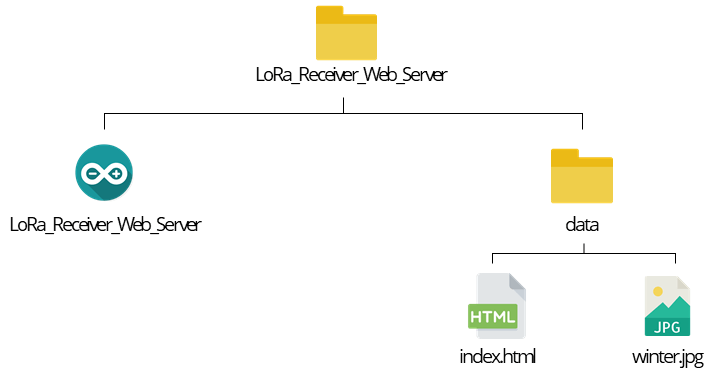
All of this, especially the need to create a webpage and host it on the board, introduces new layers of complexity compared to the transmitter sketch. To create the webserver, we need three different files; the Arduino Sketch, the HTML File, and the Images used by the HTML file. Thankfully, the ESP32 has a file system (SPIFFS) which is what is used in storing the image and the HTML files. To do this, the sketch’s file system needs to be set up as described in the image below;
We essentially need to create a sketch folder and add a “data” folder in which the image and HTML file will be stored. Start by creating the index.html file using software like notepad++ or any other editor. The index.html file contain 3 element; the HTML code which creates the basic webpage structure, the CSS style snippets (placed between <style> </style>) which ensures everything looks pretty, and the javascript lines (placed between <script> and </script>) which are responsible for updating the sensor readings on the webpage. Copy the code below and paste it in the index.html file.
The Arduino sketch basically takes data from the receiver, over LoRa, and passes it on, along with the signal strength and a timestamp that indicates when the message was received, to the webpage.
To reduce the complexity of the sketch, we will be using 3 libraries in addition to the ones used for the transmitter’s sketch. These libraries include; the NTPClient library forked by Taranis, the ESPAsyncWebServer library, and the Async TCP library.
The ESPAsyncWebserver and AsyncTCP library makes it easy to implement an asynchronous web server on the ESP, while the forked NTPClient library makes it easy to obtain network date and time which is used in time-stamping the data received from the transmitter. All these libraries are not available through the Arduino IDE’s Library Manager, as such, you will need to download them from the attached links and install them by unzipping them to the Arduino Libraries folder. Remember to restart the Arduino IDE after the installation.
Just like with the other sketch, I will do a quick run-through of the sketch explaining some of the key parts.
The sketch starts with include statements for all the libraries that will be used.
// Import Wi-Fi library
#include <WiFi.h>
#include "ESPAsyncWebServer.h"

#include <SPIFFS.h>

//Libraries for LoRa
#include <SPI.h>
#include <LoRa.h>

//Libraries for OLED Display
#include <Wire.h>
#include <Adafruit_GFX.h>
#include <Adafruit_SSD1306.h>

// Libraries to get time from NTP Server
#include <NTPClient.h>
#include <WiFiUdp.h>
Then the pins of the TTGO LoRa32 board being used by the onboard LoRa module are specified.
//define the pins used by the LoRa transceiver module
#define SCK 5
#define MISO 19
#define MOSI 27
#define SS 18
#define RST 14
#define DIO0 26
Next, the LoRa module’s frequency is specified and the pins of the TTGO LoRa32 being used by the OLED along with the display’s dimension are also specified.
//433E6 for Asia
//866E6 for Europe
//915E6 for North America
#define BAND 866E6

//OLED pins
#define OLED_SDA 4
#define OLED_SCL 15
#define OLED_RST 16
#define SCREEN_WIDTH 128 // OLED display width, in pixels
#define SCREEN_HEIGHT 64 // OLED display height, in pixels
For obvious reasons, you must ensure the frequency of the LoRa module on the receiver is the same as that of the transmitter and it’s legal to use it in projects like this in your country,
Next, provide the credentials of the WiFI access point through which the ESP is expected to connect to your local network.
// Replace with your network credentials
const char* ssid     = "REPLACE_WITH_YOUR_SSID";
const char* password = "REPLACE_WITH_YOUR_PASSWORD";
and create an NTP client to be used in fetching date and time information, along with variables to store them.
// Define NTP Client to get time
WiFiUDP ntpUDP;
NTPClient timeClient(ntpUDP);

// Variables to save date and time
String formattedDate;
String day;
String hour;
String timestamp;
We create a few more variables to store the message received from the transmitter.
// Initialize variables to get and save LoRa data
int rssi;
String loRaMessage;
String temperature;
String humidity;
String pressure;
String readingID;
and an AsyncWebServer object on port 80 and also create an instance of the SSD1306 library.
Next, we create a few functions which will be used later in the code. The functions include;the processor() function which is used to send values to the place holders created in the HTML file, the startOLED() function which is used to initialize the OLED, the startloRA() function which is used to initialize and set parameters for LoRa Communication, the connectWiFi() function which uses the SSID and password credentials to connect the TTGO LoRa32 board to your Local network, the void getTimeStamp() function which is used to obtain time information from the NTPClient, and void getLoRaData() which receives the String sent from the transmitter and breaks it down to separate each value into its corresponding variable.
// Replaces placeholder with DHT values
String processor(const String& var){
//Serial.println(var);
if(var == "TEMPERATURE"){
return temperature;
}
else if(var == "HUMIDITY"){
return humidity;
}
else if(var == "PRESSURE"){
return pressure;
}
else if(var == "TIMESTAMP"){
return timestamp;
}
else if (var == "RRSI"){
return String(rssi);
}
return String();
}
//Initialize OLED display
void startOLED(){
//reset OLED display via software
pinMode(OLED_RST, OUTPUT);
digitalWrite(OLED_RST, LOW);
delay(20);
digitalWrite(OLED_RST, HIGH);
//initialize OLED
Wire.begin(OLED_SDA, OLED_SCL);
if(!display.begin(SSD1306_SWITCHCAPVCC, 0x3c, false, false)) { // Address 0x3C for 128x32
Serial.println(F("SSD1306 allocation failed"));
for(;;); // Don't proceed, loop forever
}
display.clearDisplay();
display.setTextColor(WHITE);
display.setTextSize(1);
display.setCursor(0,0);
display.print("LORA SENDER");
}
//Initialize LoRa module
void startLoRA(){
int counter;
//SPI LoRa pins
SPI.begin(SCK, MISO, MOSI, SS);
//setup LoRa transceiver module
LoRa.setPins(SS, RST, DIO0);
while (!LoRa.begin(BAND) && counter < 10) {
Serial.print(".");
counter++;
delay(500);
}
if (counter == 10) {
// Increment readingID on every new reading
Serial.println("Starting LoRa failed!");
}
Serial.println("LoRa Initialization OK!");
display.setCursor(0,10);
display.clearDisplay();
display.print("LoRa Initializing OK!");
display.display();
delay(2000);
}
void connectWiFi(){
// Connect to Wi-Fi network with SSID and password
Serial.print("Connecting to ");
Serial.println(ssid);
WiFi.begin(ssid, password);
while (WiFi.status() != WL_CONNECTED) {
delay(500);
Serial.print(".");
}
// Print local IP address and start web server
Serial.println("");
Serial.println("WiFi connected.");
Serial.println("IP address: ");
Serial.println(WiFi.localIP());
display.setCursor(0,20);
display.print("Access web server at: ");
display.setCursor(0,30);
display.print(WiFi.localIP());
display.display();
}
// Read LoRa packet and get the sensor readings
void getLoRaData() {
Serial.print("Lora packet received: ");
// Read packet
while (LoRa.available()) {
String LoRaData = LoRa.readString();
// LoRaData format: readingID/temperature&soilMoisture#batterylevel
// String example: 1/27.43&654#95.34
Serial.print(LoRaData);
// Get readingID, temperature and soil moisture
int pos1 = LoRaData.indexOf('/');
int pos2 = LoRaData.indexOf('&');
int pos3 = LoRaData.indexOf('#');
readingID = LoRaData.substring(0, pos1);
temperature = LoRaData.substring(pos1 +1, pos2);
humidity = LoRaData.substring(pos2+1, pos3);
pressure = LoRaData.substring(pos3+1, LoRaData.length());
}
// Get RSSI
rssi = LoRa.packetRssi();
Serial.print(" with RSSI ");
Serial.println(rssi);
}
// Function to get date and time from NTPClient
void getTimeStamp() {
while(!timeClient.update()) {
timeClient.forceUpdate();
}
// The formattedDate comes with the following format:
// 2018-05-28T16:00:13Z
// We need to extract date and time
formattedDate = timeClient.getFormattedDate();
Serial.println(formattedDate);
// Extract date
int splitT = formattedDate.indexOf("T");
day = formattedDate.substring(0, splitT);
Serial.println(day);
// Extract time
hour = formattedDate.substring(splitT+1, formattedDate.length()-1);
Serial.println(hour);
timestamp = day + " " + hour;
}
Up next is the void setup() function. Just like the transmitter sketch, the creation of the functions above helps reduce the amount of code required leaving the initialization of the SPIffS system, along with the implementation of the server.on routine as the major tasks. The javascript snippet of code in the HTML file is set to update the webpage every 10 seconds, as such, it makes a request to the Arduino Sketch for data when that happens. The Server.on routine handles that request and sends all the values to the server.
The setup also includes the line of code to initialize the NTPClient and offset the data received with your timezone.
// Initialize a NTPClient to get time
timeClient.begin();
// Set offset time in seconds to adjust for your timezone, for example:
// GMT +1 = 3600
// GMT +8 = 28800
// GMT -1 = -3600
// GMT 0 = 0
timeClient.setTimeOffset(0);
}
Next, is the void loop() function. The loop starts with a line of code to listen for incoming packets which if available, the getLoRaData() and getTimeStamp() functions are called.
void loop() {
// Check if there are LoRa packets available
int packetSize = LoRa.parsePacket();
if (packetSize) {
getLoRaData();
getTimeStamp();
}
}
The complete Arduino Sketch for the receiver is provided below and also attached under the download section.
/*********
Rui Santos
Complete project details at https://RandomNerdTutorials.com/esp32-lora-sensor-web-server/
Permission is hereby granted, free of charge, to any person obtaining a copy
of this software and associated documentation files.
The above copyright notice and this permission notice shall be included in all
copies or substantial portions of the Software.
*********/
// Import Wi-Fi library
#include <WiFi.h>
#include "ESPAsyncWebServer.h"
#include <SPIFFS.h>
//Libraries for LoRa
#include <SPI.h>
#include <LoRa.h>
//Libraries for OLED Display
#include <Wire.h>
#include <Adafruit_GFX.h>
#include <Adafruit_SSD1306.h>
// Libraries to get time from NTP Server
#include <NTPClient.h>
#include <WiFiUdp.h>
//define the pins used by the LoRa transceiver module
#define SCK 5
#define MISO 19
#define MOSI 27
#define SS 18
#define RST 14
#define DIO0 26
//433E6 for Asia
//866E6 for Europe
//915E6 for North America
#define BAND 866E6
//OLED pins
#define OLED_SDA 4
#define OLED_SCL 15
#define OLED_RST 16
#define SCREEN_WIDTH 128 // OLED display width, in pixels
#define SCREEN_HEIGHT 64 // OLED display height, in pixels
// Replace with your network credentials
const char* ssid = "REPLACE_WITH_YOUR_SSID";
const char* password = "REPLACE_WITH_YOUR_PASSWORD";
// Define NTP Client to get time
WiFiUDP ntpUDP;
NTPClient timeClient(ntpUDP);
// Variables to save date and time
String formattedDate;
String day;
String hour;
String timestamp;
// Initialize variables to get and save LoRa data
int rssi;
String loRaMessage;
String temperature;
String humidity;
String pressure;
String readingID;
// Create AsyncWebServer object on port 80
AsyncWebServer server(80);

Adafruit_SSD1306 display(SCREEN_WIDTH, SCREEN_HEIGHT, &Wire, OLED_RST);
// Replaces placeholder with DHT values
String processor(const String& var){
  //Serial.println(var);
  if(var == "TEMPERATURE"){
    return temperature;
  }
  else if(var == "HUMIDITY"){
    return humidity;
  }
  else if(var == "PRESSURE"){
    return pressure;
  }
  else if(var == "TIMESTAMP"){
    return timestamp;
  }
  else if (var == "RRSI"){
    return String(rssi);
  }
  return String();
}

//Initialize OLED display
void startOLED(){
  //reset OLED display via software
  pinMode(OLED_RST, OUTPUT);
  digitalWrite(OLED_RST, LOW);
  delay(20);
  digitalWrite(OLED_RST, HIGH);

  //initialize OLED
  Wire.begin(OLED_SDA, OLED_SCL);
  if(!display.begin(SSD1306_SWITCHCAPVCC, 0x3c, false, false)) { // Address 0x3C for 128x32
    Serial.println(F("SSD1306 allocation failed"));
    for(;;); // Don't proceed, loop forever
  }
  display.clearDisplay();
  display.setTextColor(WHITE);
  display.setTextSize(1);
  display.setCursor(0,0);
  display.print("LORA SENDER");
}

//Initialize LoRa module
void startLoRA(){
  int counter;
  //SPI LoRa pins
  SPI.begin(SCK, MISO, MOSI, SS);
  //setup LoRa transceiver module
  LoRa.setPins(SS, RST, DIO0);

  while (!LoRa.begin(BAND) && counter < 10) {
    Serial.print(".");
    counter++;
    delay(500);
  }
  if (counter == 10) {
    // Increment readingID on every new reading
    Serial.println("Starting LoRa failed!");
  }
  Serial.println("LoRa Initialization OK!");
  display.setCursor(0,10);
  display.clearDisplay();
  display.print("LoRa Initializing OK!");
  display.display();
  delay(2000);
}

void connectWiFi(){
  // Connect to Wi-Fi network with SSID and password
  Serial.print("Connecting to ");
  Serial.println(ssid);
  WiFi.begin(ssid, password);
  while (WiFi.status() != WL_CONNECTED) {
    delay(500);
    Serial.print(".");
  }
  // Print local IP address and start web server
  Serial.println("");
  Serial.println("WiFi connected.");
  Serial.println("IP address: ");
  Serial.println(WiFi.localIP());
  display.setCursor(0,20);
  display.print("Access web server at: ");
  display.setCursor(0,30);
  display.print(WiFi.localIP());
  display.display();
}

// Read LoRa packet and get the sensor readings
void getLoRaData() {
  Serial.print("Lora packet received: ");
  // Read packet
  while (LoRa.available()) {
    String LoRaData = LoRa.readString();
    // LoRaData format: readingID/temperature&soilMoisture#batterylevel
    // String example: 1/27.43&654#95.34
    Serial.print(LoRaData);

    // Get readingID, temperature and soil moisture
    int pos1 = LoRaData.indexOf('/');
    int pos2 = LoRaData.indexOf('&');
    int pos3 = LoRaData.indexOf('#');
    readingID = LoRaData.substring(0, pos1);
    temperature = LoRaData.substring(pos1 +1, pos2);
    humidity = LoRaData.substring(pos2+1, pos3);
    pressure = LoRaData.substring(pos3+1, LoRaData.length());
  }
  // Get RSSI
  rssi = LoRa.packetRssi();
  Serial.print(" with RSSI ");
  Serial.println(rssi);
}

// Function to get date and time from NTPClient
void getTimeStamp() {
  while(!timeClient.update()) {
    timeClient.forceUpdate();
  }
  // The formattedDate comes with the following format:
  // 2018-05-28T16:00:13Z
  // We need to extract date and time
  formattedDate = timeClient.getFormattedDate();
  Serial.println(formattedDate);

  // Extract date
  int splitT = formattedDate.indexOf("T");
  day = formattedDate.substring(0, splitT);
  Serial.println(day);
  // Extract time
  hour = formattedDate.substring(splitT+1, formattedDate.length()-1);
  Serial.println(hour);
  timestamp = day + " " + hour;
}
void setup() {
  // Initialize Serial Monitor
  Serial.begin(115200);
  startOLED();
  startLoRA();
  connectWiFi();

  if(!SPIFFS.begin()){
    Serial.println("An Error has occurred while mounting SPIFFS");
    return;
  }
  // Route for root / web page
  server.on("/", HTTP_GET, [](AsyncWebServerRequest *request){
    request->send(SPIFFS, "/index.html", String(), false, processor);
  });
  server.on("/temperature", HTTP_GET, [](AsyncWebServerRequest *request){
    request->send_P(200, "text/plain", temperature.c_str());
  });
  server.on("/humidity", HTTP_GET, [](AsyncWebServerRequest *request){
    request->send_P(200, "text/plain", humidity.c_str());
  });
  server.on("/pressure", HTTP_GET, [](AsyncWebServerRequest *request){
    request->send_P(200, "text/plain", pressure.c_str());
  });
  server.on("/timestamp", HTTP_GET, [](AsyncWebServerRequest *request){
    request->send_P(200, "text/plain", timestamp.c_str());
  });
  server.on("/rssi", HTTP_GET, [](AsyncWebServerRequest *request){
    request->send_P(200, "text/plain", String(rssi).c_str());
  });
  server.on("/winter", HTTP_GET, [](AsyncWebServerRequest *request){
    request->send(SPIFFS, "/winter.jpg", "image/jpg");
  });
  // Start server
  server.begin();
  // Initialize a NTPClient to get time
  timeClient.begin();
  // Set offset time in seconds to adjust for your timezone, for example:
  // GMT +1 = 3600
  // GMT +8 = 28800
  // GMT -1 = -3600
  // GMT 0 = 0
  timeClient.setTimeOffset(0);
}
void loop() {
  // Check if there are LoRa packets available
  int packetSize = LoRa.parsePacket();
  if (packetSize) {
    getLoRaData();
    getTimeStamp();
  }
}
With the sketch saved, go to the sketch folder and create a folder called data. Move the image and the index.html file we created earlier into the folder so the file hierarchy looks as we described earlier. With that done, we are ready to upload the sketches and test the project.
Demo
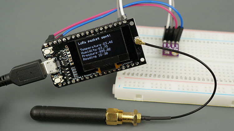
For the transmitter, connect the setup to your computer, ensure you select the right port and board type (in this case, the TTGO LoRa32-OLED V1.) and hit the upload button. If successful, you should see the OLED come up with the latest temperature, humidity, and pressure data as shown in the image below.
The serial monitor should also show the LoRa Transmission progress. Since we did not include a way to check if the data was received, the transmitter will keep sending the data out.
The upload mechanism for the receiver is a bit different. We need to first upload the Data file to the SPIFFS using the ESP32 Filesystem Uploader we installed earlier, after which we upload the main sketch. With the HTML file and image in the right directory, go to tools, select the right port, and board type(), then click the ESP32 Sketch Data Upload option.
After a few seconds, the data file should be successfully uploaded. Now upload the sketch to the board using the IDE’s upload button.With the upload completed, open the serial monitor. You should see the IP address along with LoRa Packets being received from the transmitter (you can power the transmitter with a battery or any other power source for this).
Enter the IP address into the address bar of a browser on any device on the same network as the ESP. you should see the webserver displayed with the latest sensor readings as shown in the image below.
There are dozens of ways to take the project forward. You could decide to hook up the receiver to the internet and instead of a local server, report the data to a globally accessible webpage. You could also decide to retain the local network features but have it display data from multiple transmitters (sensors).
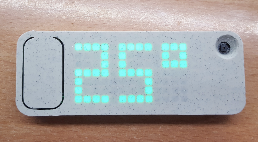
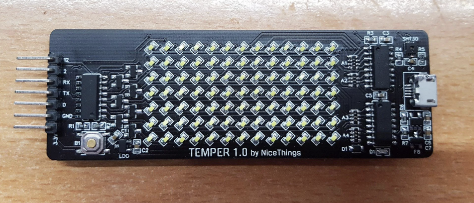
Meet Temper, a compact, low power temperature sensor based on ESP8266 and SHT30 with a large 13×7 pixel led display. It accesses WiFi periodically to display temperature and humidity data as well as battery percentage via the MQTT protocol. The device’s display uses three 74HC595 + 7 n-fets, TP4054 to handle battery charging through a USB and MCP1700T LDO to power the ESP.
For WiFi setup, Temper comes with a super simple Web config interface and is also compatible with a home assistant and it’s auto-discovery feature. It can also be used with any platform that supports MQTT and can be attached to walls using magnets.
The case for the device is a stone-age light (PLA) from Spectrum filaments. It comes with a large reset button on the left forces the device to request MQTT temperature data and displays it within 5s after the button press.
“The ESP is set to wake up every hour to send the temperature to MQTT. Pushing a button (hard resetting it) will show the temperature on the display and battery status as well. It should be able to make half a year of battery life or more (during deep sleep, it draws 32uA which is beyond awesome). This, of course, is not perfect and an e-ink display would make more sense to keep the values visible but also would quadruple the cost of the thing (but I ordered some e-inks anyway :D).”
He also notes that:
“There is a simple battery sensing onboard to keep an eye on battery level. Battery sensing is also used as a trigger for the config portal as there was not enough place for more buttons. How it works is after each button push (hard reset), it will check the battery level. If the battery level is above the threshold, it will start the configuration access point (for wifi settings, MQTT, etc.).”
Martin says he won’t be selling Temper himself, stating that they are “overwhelmingly time-consuming” to make by himself. However, the firmware and documentation are neatly documented on Github with some more helpful information on the wiki.
To put the project together you will the items listed below along with some experience with hot air soldering/ reflow oven.
Hot air station and/or reflow oven (SHT30 has pins at the bottom, that can’t be hand-soldered)
Components listed in the “PCB and BOM” directory of the GitHub repo.
You will notice on the board that the GPIO2 and GPIO12 are broken out, GPIO12 is safe for any use, but GPIO2 has to be pulled high on startup or the ESP won’t boot up correctly.
More information on the project and it’s build instructions can be found on its GitHub project page.
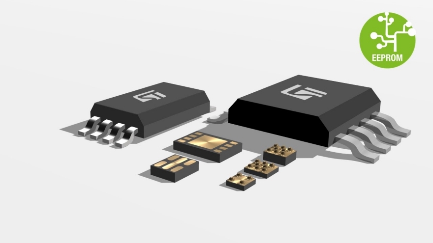
The M95M04 devices are electrically erasable programmable memories (EEPROMs) organized as 524288 x 8 bits, accessed through the SPI bus.
The M95M04 can operate with a supply range from 1.8 to 5.5 V, and is guaranteed over the -40 °C/+85 °C temperature range. The M95M04 offer an additional page, named the Identification page (512 bytes). The Identification page can be used to store sensitive application parameters that can be (later) permanently locked in read-only mode.
Key Features
Compatible with the serial peripheral interface (SPI) bus
