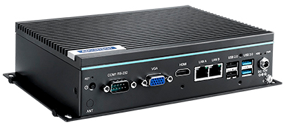
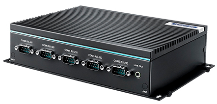
Advantech, a leading provider of industrial computing platforms, is pleased to announce the UNO-247—a fanless entry-level Internet of Things (IoT) edge computer aimed at information technology (IT) applications. Equipped with an Intel Celeron J3455 processor, comprehensive I/O ports, and VGA, and HDMI display interfaces, UNO-247 is designed to deliver edge computing power at a competitive price. To ensure flexible configuration and easy deployment for diverse industries, the system I/O includes 4 x USB, 2 x GigaLAN, 4 x RS-232, and 2 x RS-485 ports. The fanless design reduces the accumulation of dust and foreign contaminants in harsh environments, while the threaded DC jack enables locking to prevent unexpected power disconnections or interruptions. Overall, the UNO-247 provides a reliable edge gateway solution that can be configured according to specific applications, such as factory automation and environment monitoring.
Optimized Form Factor for Easy Assembly and Convenient Maintenance
Advantech’s UNO-247 is a compact platform that ensures convenient installation with high applicability and integration potential. The entire form factor has been optimized for internal space savings, an increased mean time before failure (MTBF), more reliable signal transmissions, and higher shock and vibration tolerance. Moreover, to reduce system downtime and ensure convenient maintenance, the platform’s mechanical design has been improved to enable memory installation/swapping without disassembling the entire chassis.
Fanless Platform with Lockable DC Jack for Industrial Environments
The UNO-247 features a fanless design that reduces the accumulation of dust and foreign contaminants, making it suitable for operation in harsh industrial environments. To prevent unexpected power disconnections or interruptions, the UNO-247 power adaptor is equipped with a threaded DC jack that allows the connector to be locked in place, ensuring a stable and reliable power supply.
Cost-Efficient Software-Ready Solution with Comprehensive I/O
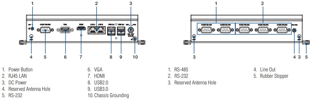
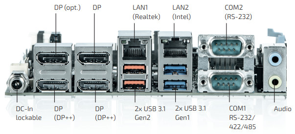
Powered by an Intel® Celeron J3455 processor equipped with 4 x USB, 2 x GigaLAN, 4 x RS-232, and 2 x RS-485 ports, as well as 1 x VGA and 1 x HDMI, UNO-247 delivers comprehensive I/O to facilitate a wide range of applications. Moreover, UNO-247 supports the Windows 10 LTSC and Linux operating systems, and can be equipped with Advantech’s WISE-PaaS/DeviceOn software solution to enable remote monitoring and management. The extensive system features and software-ready design make the UNO-247 a cost-efficient intelligent edge gateway ideal for diverse IoT operations.
UNO-247 ports detail
Key Features
Intel Celeron J3455 processor
Robust system with high stability
2 x GbE, 2 x USB 3.0, 2 x USB 2.0, 4 x RS-232, 2 x RS485, 1 x HDMI, 1 x VGA
Compact form factor with fanless design
Rubber stopper design for stand mount and optional kit for DIN-rail mounting
Optional 3G/GPS/GPRS/Wi-Fi communication
Threaded DC jack for connection stability
Optimized mechanical design for easy RAM installation
Advantech’s UNO-247 fanless entry-level IoT edge computer is available for order now. For more information about this or other Advantech products and services, contact your local sales support team or visit the Advantech website at www.advantech.com.
Ideal for demanding graphics applications in professional casino gaming systems, medical displays, thin clients and industrial PCs through AMD Radeon™ Vega Graphics
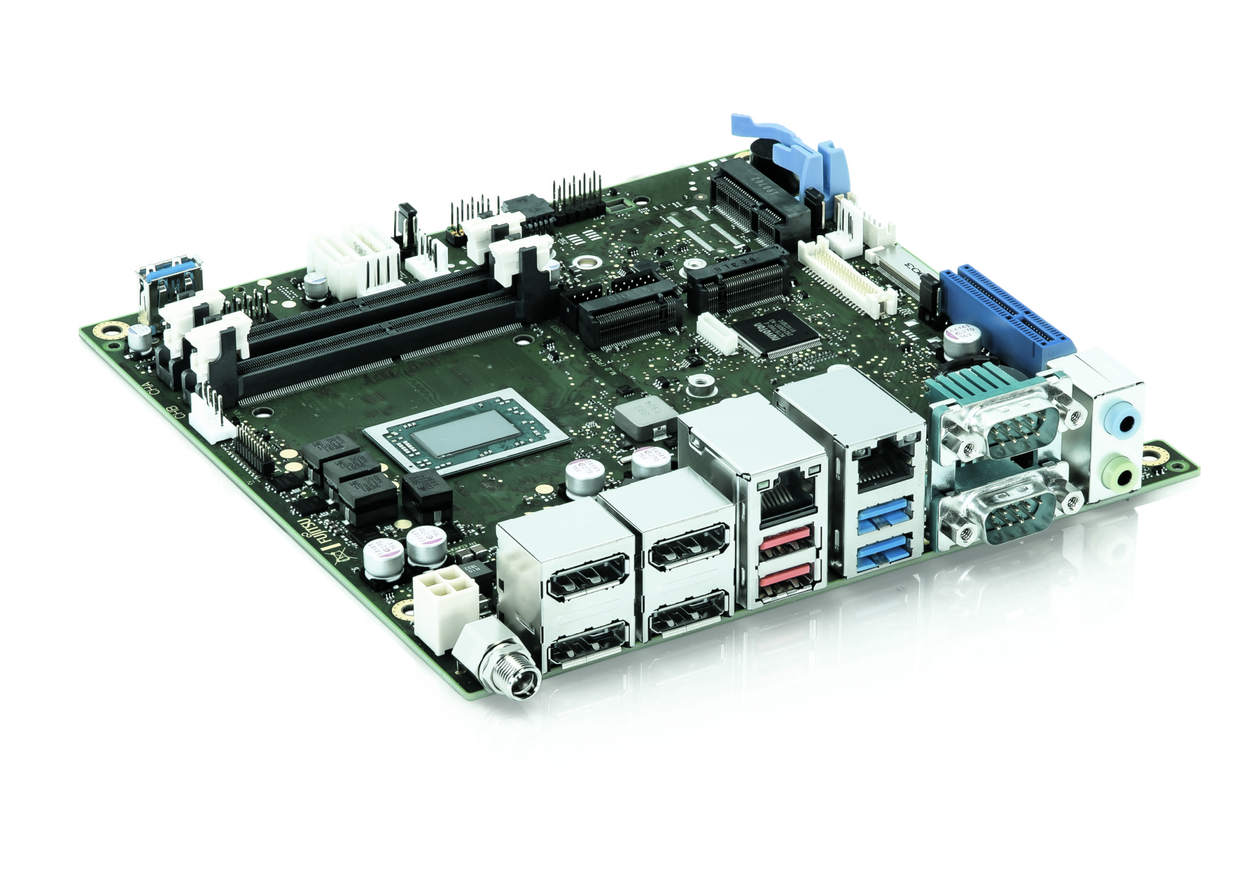
Kontron, a leading global provider of IoT/Embedded Computing Technology (ECT), will present the D3713-V/R mITX industrial motherboard based on the AMD Ryzen™ Embedded V1000 and R1000 line at this year’s embedded world tradeshow. It features the SoC integrated AMD Radeon™ Vega GPU with particularly brilliant graphics and supports up to four independent displays in 4K resolution via DisplayPorts, one Embedded DisplayPort and a dual-channel LVDS (24bit). With five different AMD processors, the board can be adapted for various graphics applications, e.g. for kiosk, infotainment, digital signage, professional casino gaming systems, as well as medical displays, thin clients and industrial PCs.
The Kontron D3713-V/R mITX motherboard is “Designed by Fujitsu” and manufactured in Germany. This guarantees short delivery times, highest manufacturing quality, competent technical support directly from Augsburg, as well as long-term repair service. Kontron also offers a “kitting” service, where motherboards are assembled ‘ex factory’ with the requested processors, memory latches and even an individual BIOS.
D3713-V/R mITX port details
For the D3713-V/R mITX motherboard, the Kontron SMARTCASE™ S711 is also currently in preparation. It offers a customer-specific configured and certified system solution consisting of the board, CPU, memory, expansion cards, BIOS, cooling and housing.
The D3713-V/R mITX motherboard optionally offers different processors of the AMD Ryzen™ Embedded V1000 and R1000 line: AMD Embedded SoC V1202B, V1605B, V1807B, R1305G or R1606G. Due to the Intel® i210LM Ethernet Controller with 10/100/1000 MBit/s the board supports protocols such as EtherCAT or TSN. Furthermore it offers 2x SO DIMM sockets for up to 32GB memory. The use of a data carrier or extensions is possible via 2x Serial ATA III 600 interfaces (up to 6GBit/s), a Mini PCIe (halfsize/fullsize), a PCI Express® x4 Gen3, an M.2 PCIe x2 Key-M and an M.2 PCIe x4 Key B. It also offers various interfaces, such as USB 3.1 Gen1/Gen2, USB 2.0, serial I/O, GPIO and High Definition Audio Input/Output via the Realtek ALC256 chip codec. The board contains an AMI Aptio 5.x (UEFI) BIOS, a HW Watchdog, a BIOS integrated HW Diagnostic Tool, AMD integrated TPM V2.0 onboard, and a socket for an optional TPM module.
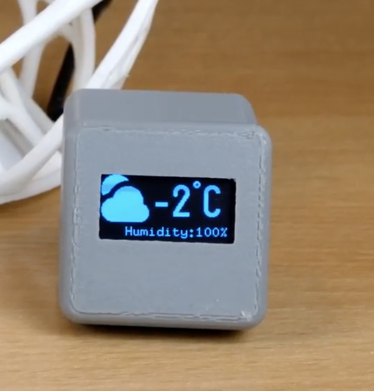
A few years back I wrote this tutorial on connected weather monitor with plans of creating a 3D printed enclosure to make it portable and easy to use. I never got around doing that but a few days ago, I came across a similar project built by BitsandBlobs, which went as far as creating the 3D enclosure and I thought their example will be a fun way of sharing the project. So for today’s tutorial, we will build a Connected Weather Widget.
The Weather Widget (Credits: bitsandblobs)
Having an idea of what the current weather conditions are, or what it will look like in a couple of hours or days, has proven to be very useful, not just when it ensures you don’t get caught in the rain without your coat, but also for different important scenarios across different industries like Agriculture, Advertising, Transportation and even Warfare.
While one could build a weather monitoring station to get weather information about a particular place, there are scenarios where you want to obtain weather information about places where you do not have a station. For these scenarios, people usually turn to the news or their phone, but with everyone trying to reduce the amount of time spends with their phone, maybe it will be a good idea to have a device which provides you the weather information without the usual temptation to check your APP feed. This is what we are going to build today.
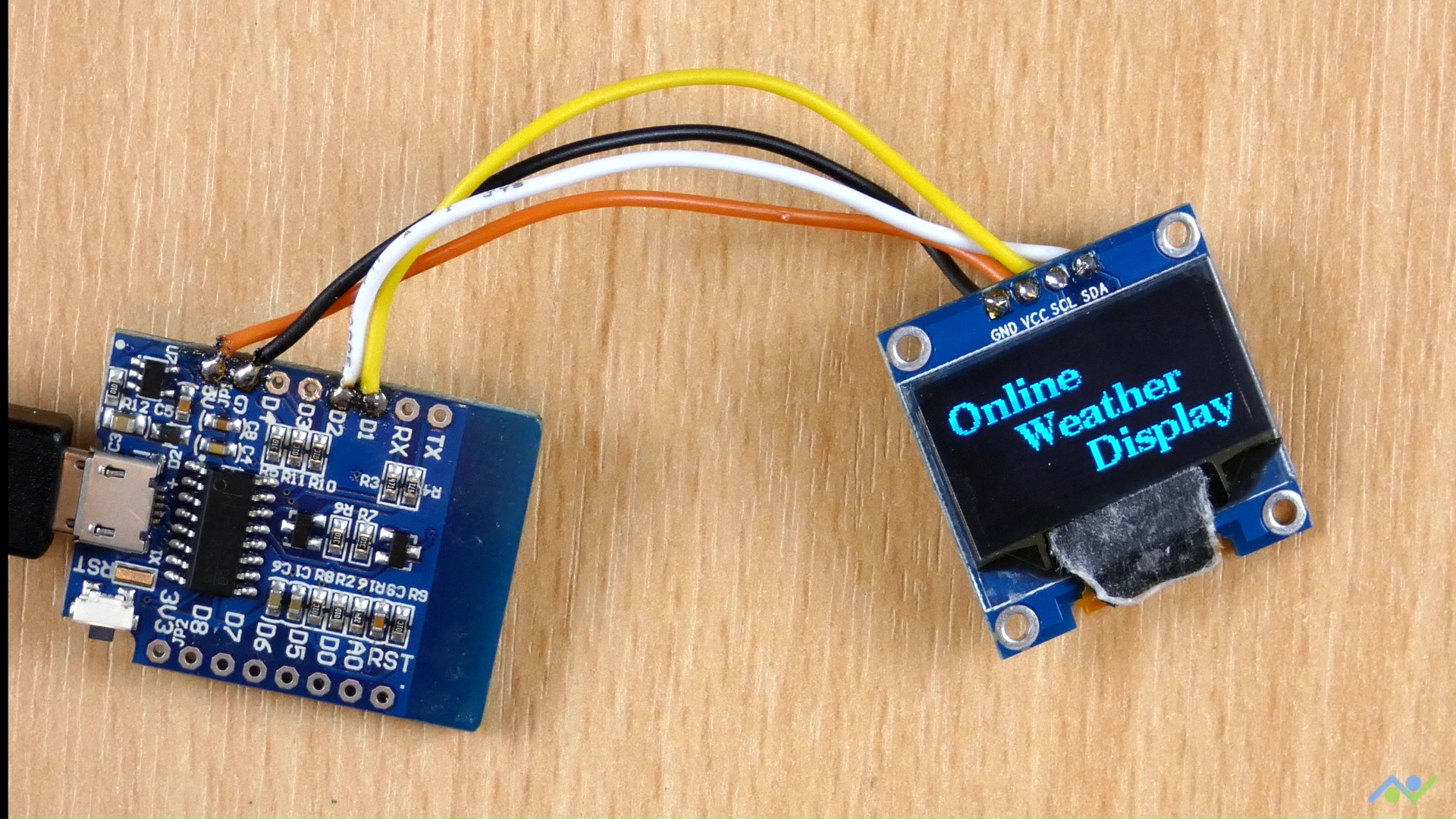
The project uses the WiFi features of the Wemos D1 mini to connect to an online open-source weather monitoring platform called OpenWeatherMap, where it obtains the required weather information, sorts it and displays it on the OLED.
At the end of today’s tutorial, you would know how to interface an OLED with the Wemos D1 and also obtain weather information from” OpenWeatherMap”.
Required Components
The following components are required to build this project;
All components can be bought from the attached links. While the components are soldered together for this project, you can choose to implement the project on a breadboard or even take things further and provide a backup battery to power the device instead of a USB. This is why the optional components have been added to the list.
Schematics
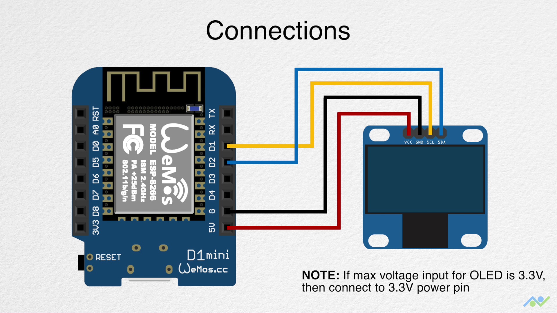
The use of just two components makes the schematics for this project quite straight forward. The OLED communicates with host microcontroller over I2C, as such, all we need to do is to connect it to the I2C pins of the Wemos D1 as shown below:
Schematic (Credits: bitsandblobs)
To make the schematics easier to follow, a pin-pin map showing how to components are connected is provided below:
OLED – Wemos D1 Mini
SCL - D1
SDA - D2
VCC - 5v
GND - GND
It is important to note the maximum input voltage of your OLED display and be sure it is 5V tolerant. You should connect the VCC pin of the OLED to the Wemos D1’s 3.3v pin if 5V is too high for the display.
Obtain OpenWeatherMap Credentials
As mentioned during the introduction, the weather information to be displayed on the OLED will be obtained from OpenWeatherMap, as such, before we proceed to write the code for this project, it is important to Signup and obtain the credentials, in this case, an API key, that will be used by our device to connect to the service.
To do this follow the steps below:
1. Point your web browser to OpenWeatherMaps Website and hit the “Sign up” button. If you already have an OpenWeatherMap account, just skip to the 3rd step.
2. Once the signup page opens, fill in all the necessary details and click on create an account. If successful, you will be automatically subscribed to the free OpenWeatherMap plan which will allow you to perform up to 60 API calls per minute among other perks. Since this is just a demo project, I believe this to be good enough but if you’d like more access, you can check out some of the other packages and subscribe to them if needed.
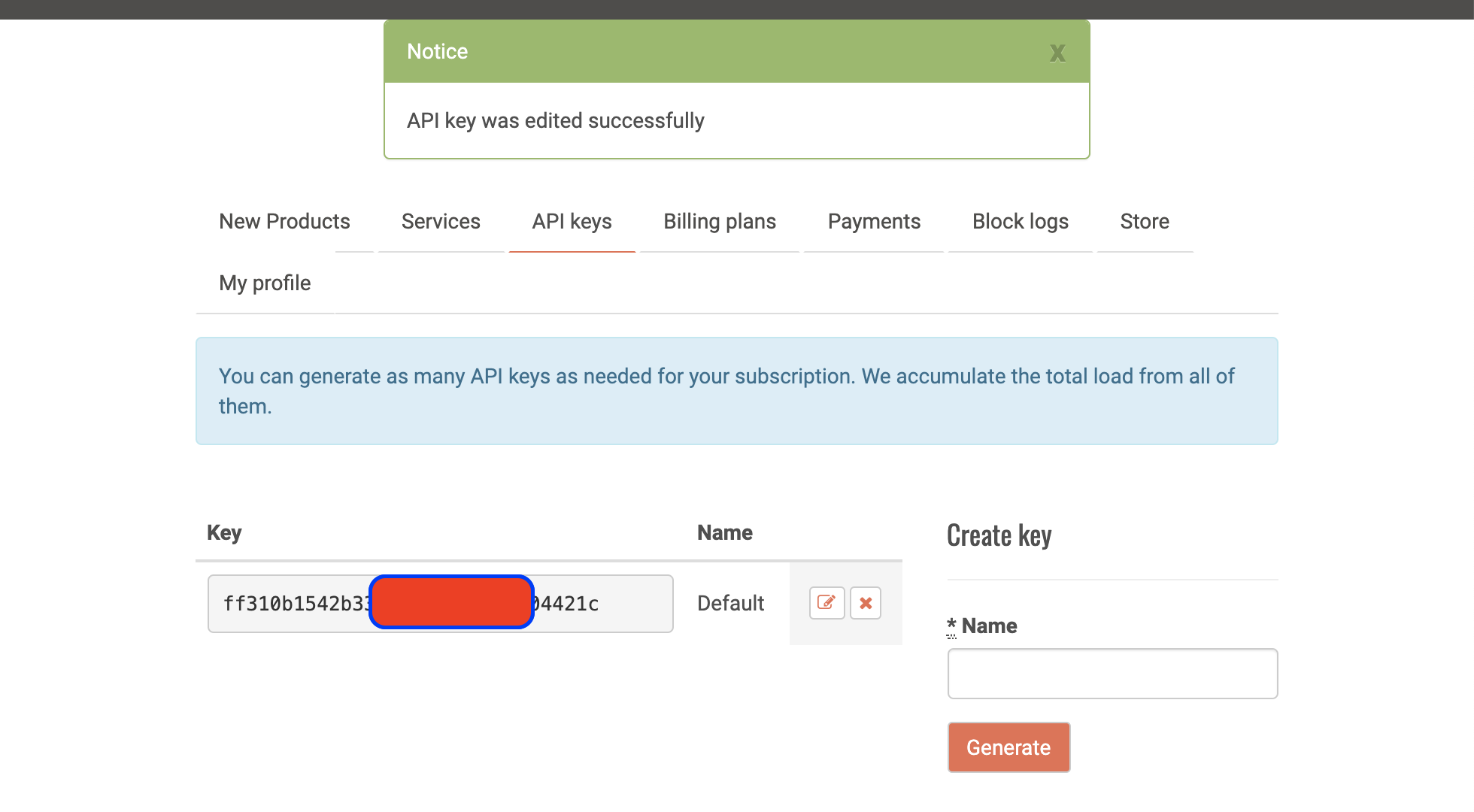
3. With registration complete, select the API Keys tab at the top of the resulting page. It should lead to a page with your API Key displayed as shown in the image below:
Copy the API key and paste in a notepad or any other safe place. We will need it for our code.
With this done successfully, we can proceed to write the code for the project.
Code
The Arduino IDE was used in developing the code for this project, as such, if this is the first time you are using an ESP8266 based board with the IDE, you will need to install the ESP8266 support for it. Follow this tutorial we wrote a while back on “Programming an ESP8266 Board with the Arduino IDE” to get it done.
The logic behind the code for the project is quite straight forward. We start by connecting the device to a WiFi access point through which it will access the OpenWeatherMaps server using the API key we obtained earlier. The response from OpenWeatherMap to the API call is parsed and the weather information contained is displayed on the OLED display.
The response from OpenWeatherMap is usually a JSON file, as such, to easily parse the data to obtain the information we need, we will use the Arduino Json Library which was created to help with creating or Parsing JSON files. We will also use the ESP8266 WIFI library, which will handle all network-related tasks, and the U8g2lib library to make interacting with the OLED seamless. All of the above libraries can be installed via the Arduino Library Manager or by downloading from the links attached to them and installing them manually.
As usual, I will do a quick run through the sketch and explain parts of it that I feel might be a little bit difficult to follow.
The sketch starts, as usual, with the inclusion of the libraries we will be using.
//Written  By Frenoy Osburn
// Modified by Emmanuel Odunlade

#include <ESP8266WiFi.h>
#include <stdio.h>
#include <ArduinoJson.h>
#include <U8g2lib.h>
Next, we create variables that are matched to different weather conditions with 0 representing the sun and 4 representing thunder.
Next, we create an instance of the U8G2 library with the I2C pins of the Wemos D1 as arguments.
U8G2_SSD1306_128X64_NONAME_1_SW_I2C u8g2(U8G2_R0, /* clock=*/ SCL, /* data=*/ SDA, /* reset=*/ U8X8_PIN_NONE); // All Boards without Reset of the Display
Next, we supply the credentials of the WiFI access point through which the device will access the internet and create a few more variables to be used in tracking time within the code.
//initiate the WifiClient
WiFiClient client;
const char* ssid = "mySSID";
const char* password = "myPASSWORD";
unsigned long lastCallTime = 0; // last time you called the updateWeather function, in milliseconds
const unsigned long postingInterval = 30L * 1000L; // delay between updates, in milliseconds
Next, we create a variable to hold the API key we obtained earlier from OpenWeatherMap and the name of your city or the city whose weather report you are interested in. Do note the format in which the name of the city was written in my example and write yours the same way.
String APIKEY = "put your APIKEY here";
String NameOfCity = "put the name of the city you will like to get data for here" //e.g Lagos, NG if your city is Lagos in Nigeria.
With this done, we proceed to the void setup() function.
We start the function by initializing the OLED and creating a page which will serve as a splash screen for the device.
void setup()
{
u8g2.begin();
u8g2.firstPage();
do {
u8g2.setFont(u8g2_font_ncenB14_tr);
u8g2.drawStr(0,20,"Online");
u8g2.drawStr(28,40,"Weather");
u8g2.drawStr(56,60,"Display");
} while ( u8g2.nextPage() );
Next, we enable the display of UTF8 symbols on the display so it’s easy to do display things like degrees among others.
u8g2.enableUTF8Print(); //for the degree symbol
Next, we initialize the serial monitor for debugging purposes and kickstart wifi communications by connecting to the APN credentials we provided earlier.
Serial.begin(115200);
Serial.println("\n\nOnline Weather Display\n");
Serial.println("Connecting to network");
WiFi.begin(ssid, password);
int counter = 0;
while (WiFi.status() != WL_CONNECTED)
{
delay(200);
if (++counter > 100)
ESP.restart();
Serial.print( "." );
}
Serial.println("\nWiFi connected");
printWifiStatus();
}
Next is the void loop() function.
The loop() function for this project simply calls the UpdateWeather function at certain intervals defined by the difference between when the last call was made and the current program run time.
Next, is the void updateWeather() function. The function, when called within the loop() function, connects to the OpenWeatherMap servers and uses the API key and the city name we provided go send a request for weather information to the server.
void updateWeather()
{
// if there's a successful connection:
if (client.connect("api.openweathermap.org", 80))
{
Serial.println("Connecting to OpenWeatherMap server...");
// send the HTTP PUT request:
client.println("GET /data/2.5/weather?q=" + NameOfCity + "&units=metric&APPID=" + APIKEY + "HTTP/1.1");
client.println("Host: api.openweathermap.org");
client.println("Connection: close");
client.println();
If the server responds with the data, it is passed and each one is stored with a matching variable name.
// Check HTTP status
char status[32] = {0};
client.readBytesUntil('\r', status, sizeof(status));
// It should be "HTTP/1.0 200 OK" or "HTTP/1.1 200 OK"
if (strcmp(status + 9, "200 OK") != 0)
{
Serial.print(F("Unexpected response: "));
Serial.println(status);
return;
}
// Skip HTTP headers
char endOfHeaders[] = "\r\n\r\n";
if (!client.find(endOfHeaders))
{
Serial.println(F("Invalid response"));
return;
}
// Allocate the JSON document
// Use arduinojson.org/v6/assistant to compute the capacity.
const size_t capacity = JSON_ARRAY_SIZE(1) + JSON_OBJECT_SIZE(1) + 2*JSON_OBJECT_SIZE(2) + JSON_OBJECT_SIZE(4) + 2*JSON_OBJECT_SIZE(5) + JSON_OBJECT_SIZE(13) + 270;
DynamicJsonDocument doc(capacity);
// Parse JSON object
DeserializationError error = deserializeJson(doc, client);
if (error) {
Serial.print(F("deserializeJson() failed: "));
Serial.println(error.c_str());
return;
}
int weatherId = doc["weather"][0]["id"].as<int>();
float weatherTemperature = doc["main"]["temp"].as<float>();
int weatherHumidity = doc["main"]["humidity"].as<int>();
The response is displayed on the serial monitor and the corresponding weather status is printed on the OLED.
Serial.println(F("Response:"));
Serial.print("Weather: ");
Serial.println(weatherId);
Serial.print("Temperature: ");
Serial.println(weatherTemperature);
Serial.print("Humidity: ");
Serial.println(weatherHumidity);
Serial.println();
char scrollText[15];
sprintf(scrollText, "Humidity:%3d%%", weatherHumidity);
if(weatherId == 800) //clear
{
draw(scrollText, SUN, weatherTemperature);
}
else
{
switch(weatherId/100)
{
case 2: //Thunderstorm
draw(scrollText, THUNDER, weatherTemperature);
break;
case 3: //Drizzle
case 5: //Rain
draw(scrollText, RAIN, weatherTemperature);
break;
case 7: //Sun with clouds
draw(scrollText, SUN_CLOUD, weatherTemperature);
break;
case 8: //clouds
draw(scrollText, CLOUD, weatherTemperature);
break;
default: //Sun with clouds
draw(scrollText, SUN_CLOUD, weatherTemperature);
break;
}
}
}
else
{
// if you couldn't make a connection:
Serial.println("connection failed");
}
// note the time that this function was called
lastCallTime = millis();
}
The code contains a few more functions that are used in displaying the icons. It is quite self-explanatory and you should get the idea. You can also check out one of our past tutorials on “creating custom graphics for displays” to understand better.
The complete sketch is provided below:
//Written By Frenoy Osburn
// Modified by Emmanuel Odunlade
#include <ESP8266WiFi.h>
#include <stdio.h>
#include <ArduinoJson.h>
#include <U8g2lib.h>
#define SUN  0
#define SUN_CLOUD  1
#define CLOUD 2
#define RAIN 3
#define THUNDER 4
U8G2_SSD1306_128X64_NONAME_1_SW_I2C u8g2(U8G2_R0, /* clock=*/ SCL, /* data=*/ SDA, /* reset=*/ U8X8_PIN_NONE); // All Boards without Reset of the Display
//initiate the WifiClient
WiFiClient client;

const char* ssid = "mySSID";
const char* password = "myPASSWORD";
unsigned long lastCallTime = 0;               // last time you called the updateWeather function, in milliseconds
const unsigned long postingInterval = 30L * 1000L;  // delay between updates, in milliseconds
String APIKEY = "put your APIKEY here";
String NameOfCity = "put the name of the city you will like to get data for here" //e.g Lagos, NG if your city is Lagos in Nigeria.
void setup()
{
  u8g2.begin();

  u8g2.firstPage();
  do {
    u8g2.setFont(u8g2_font_ncenB14_tr);
    u8g2.drawStr(0,20,"Online");
    u8g2.drawStr(28,40,"Weather");
    u8g2.drawStr(56,60,"Display");
  } while ( u8g2.nextPage() );
u8g2.enableUTF8Print(); //for the degree symbol
Serial.begin(115200);
  Serial.println("\n\nOnline Weather Display\n");

  Serial.println("Connecting to network");
  WiFi.begin(ssid, password);

  int counter = 0;
  while (WiFi.status() != WL_CONNECTED)
  {
    delay(200);
    if (++counter > 100)
      ESP.restart();
    Serial.print( "." );
  }
  Serial.println("\nWiFi connected");
  printWifiStatus();
}
void loop()
{
  if (millis() - lastCallTime > postingInterval)
  {
    updateWeather();
  }
}
void updateWeather()
{
  // if there's a successful connection:
  if (client.connect("api.openweathermap.org", 80))
  {
    Serial.println("Connecting to OpenWeatherMap server...");
    // send the HTTP PUT request:
    client.println("GET /data/2.5/weather?q=" + NameOfCity + "&units=metric&APPID=" + APIKEY + "HTTP/1.1");
    client.println("Host: api.openweathermap.org");
    client.println("Connection: close");
    client.println();
// Check HTTP status
    char status[32] = {0};
    client.readBytesUntil('\r', status, sizeof(status));
    // It should be "HTTP/1.0 200 OK" or "HTTP/1.1 200 OK"
    if (strcmp(status + 9, "200 OK") != 0)
    {
      Serial.print(F("Unexpected response: "));
      Serial.println(status);
      return;
    }

    // Skip HTTP headers
    char endOfHeaders[] = "\r\n\r\n";
    if (!client.find(endOfHeaders))
    {
      Serial.println(F("Invalid response"));
      return;
    }

    // Allocate the JSON document
    // Use arduinojson.org/v6/assistant to compute the capacity.
    const size_t capacity = JSON_ARRAY_SIZE(1) + JSON_OBJECT_SIZE(1) + 2*JSON_OBJECT_SIZE(2) + JSON_OBJECT_SIZE(4) + 2*JSON_OBJECT_SIZE(5) + JSON_OBJECT_SIZE(13) + 270;
    DynamicJsonDocument doc(capacity);

    // Parse JSON object
    DeserializationError error = deserializeJson(doc, client);
    if (error) {
      Serial.print(F("deserializeJson() failed: "));
      Serial.println(error.c_str());
      return;
    }

    int weatherId = doc["weather"][0]["id"].as<int>();
    float weatherTemperature = doc["main"]["temp"].as<float>();
    int weatherHumidity = doc["main"]["humidity"].as<int>();
//Disconnect
client.stop();
Serial.println(F("Response:"));
    Serial.print("Weather: ");
    Serial.println(weatherId);
    Serial.print("Temperature: ");
    Serial.println(weatherTemperature);
    Serial.print("Humidity: ");
    Serial.println(weatherHumidity);
    Serial.println();

    char scrollText[15];
    sprintf(scrollText, "Humidity:%3d%%", weatherHumidity);

    if(weatherId == 800)    //clear
    {
      draw(scrollText, SUN, weatherTemperature);
    }
    else
    {
      switch(weatherId/100)
      {
        case 2:     //Thunderstorm
            draw(scrollText, THUNDER, weatherTemperature);
            break;

        case 3:     //Drizzle
        case 5:     //Rain
            draw(scrollText, RAIN, weatherTemperature);
            break;

        case 7:     //Sun with clouds
            draw(scrollText, SUN_CLOUD, weatherTemperature);
            break;
        case 8:     //clouds
            draw(scrollText, CLOUD, weatherTemperature);
            break;

        default:    //Sun with clouds
            draw(scrollText, SUN_CLOUD, weatherTemperature);
            break;
      }
    }
  }
  else
  {
    // if you couldn't make a connection:
    Serial.println("connection failed");
  }

  // note the time that this function was called
   lastCallTime = millis();
}
void printWifiStatus()
{
// print the SSID of the network you're attached to:
Serial.print("SSID: ");
Serial.println(WiFi.SSID());
// print your board's IP address:
IPAddress ip = WiFi.localIP();
Serial.print("IP Address: ");
Serial.println(ip);
// print the received signal strength:
long rssi = WiFi.RSSI();
Serial.print("signal strength (RSSI):");
Serial.print(rssi);
Serial.println(" dBm");
}
void drawWeatherSymbol(u8g2_uint_t x, u8g2_uint_t y, uint8_t symbol)
{
// fonts used:
// u8g2_font_open_iconic_embedded_6x_t
// u8g2_font_open_iconic_weather_6x_t
// encoding values, see: https://github.com/olikraus/u8g2/wiki/fntgrpiconic
switch(symbol)
{
case SUN:
u8g2.setFont(u8g2_font_open_iconic_weather_6x_t);
u8g2.drawGlyph(x, y, 69);
break;
case SUN_CLOUD:
u8g2.setFont(u8g2_font_open_iconic_weather_6x_t);
u8g2.drawGlyph(x, y, 65);
break;
case CLOUD:
u8g2.setFont(u8g2_font_open_iconic_weather_6x_t);
u8g2.drawGlyph(x, y, 64);
break;
case RAIN:
u8g2.setFont(u8g2_font_open_iconic_weather_6x_t);
u8g2.drawGlyph(x, y, 67);
break;
case THUNDER:
u8g2.setFont(u8g2_font_open_iconic_embedded_6x_t);
u8g2.drawGlyph(x, y, 67);
break;
}
}
void drawWeather(uint8_t symbol, int degree)
{
drawWeatherSymbol(0, 48, symbol);
u8g2.setFont(u8g2_font_logisoso32_tf);
u8g2.setCursor(48+3, 42);
u8g2.print(degree);
u8g2.print("°C"); // requires enableUTF8Print()
}
/*
Draw a string with specified pixel offset.
The offset can be negative.
Limitation: The monochrome font with 8 pixel per glyph
*/
void drawScrollString(int16_t offset, const char *s)
{
static char buf[36]; // should for screen with up to 256 pixel width
size_t len;
size_t char_offset = 0;
u8g2_uint_t dx = 0;
size_t visible = 0;
len = strlen(s);
if ( offset < 0 )
{
char_offset = (-offset)/8;
dx = offset + char_offset*8;
if ( char_offset >= u8g2.getDisplayWidth()/8 )
return;
visible = u8g2.getDisplayWidth()/8-char_offset+1;
strncpy(buf, s, visible);
buf[visible] = '\0';
u8g2.setFont(u8g2_font_8x13_mf);
u8g2.drawStr(char_offset*8-dx, 62, buf);
}
else
{
char_offset = offset / 8;
if ( char_offset >= len )
return; // nothing visible
dx = offset - char_offset*8;
visible = len - char_offset;
if ( visible > u8g2.getDisplayWidth()/8+1 )
visible = u8g2.getDisplayWidth()/8+1;
strncpy(buf, s+char_offset, visible);
buf[visible] = '\0';
u8g2.setFont(u8g2_font_8x13_mf);
u8g2.drawStr(-dx, 62, buf);
}
}
void draw(const char *s, uint8_t symbol, int degree)
{
int16_t offset = -(int16_t)u8g2.getDisplayWidth();
int16_t len = strlen(s);
for(;;)
{
u8g2.firstPage();
do {
drawWeather(symbol, degree);
drawScrollString(offset, s);
} while ( u8g2.nextPage() );
delay(20);
offset+=2;
if ( offset > len*8+1 )
break;
}
}
Demo
Go over the connections again and ensure you have the ESP8266’s Arduino IDE board support package installed along with the U8g2 library. Once confirmed, connect the Wemos D1 to your computer and select it in the Arduino IDE along with the port to which it is connected. Hit the upload button and wait for the completion of the upload process. When completed, you should see the weather information displayed on the OLED as shown in the image below.
Demo (Credits: bitsandblobs)
To take things further, a nice improvement BitsandBlobs made compared to my own project was the creation of a 3D printed enclosure to house the device. It makes the project look really nice and presentable, and it’s one of the reasons why I decided to share it here. The design and assembly instructions of the enclosure are available on Thingiverse, so all you need to do is to download and print it. After putting it in the 3D printed enclosure, the device should look like the image below.
Demo (Credits: bitsandblobs)
That’s it for this tutorial, thanks for reading. Do let me know via the comment section if you built one of these and also let me know if you have any challenges replicating them.
Periodic signals are not always perfect sinusoidal patterns such as presented in one of our previous tutorials about Sinusoidal Waveforms. Sometimes, signals can indeed be a superposition of simple sine waves and they are known as complex waveforms.
In this tutorial, we will focus on complex periodic waveforms to understand what they consist of and how they can be analyzed.
First of all, we present the concept of harmonics along with the spectrum representation. In the second section, we focus on spectral analysis, which is the mathematical tool to analyze harmonics, based on the Fourier series.
Presentation
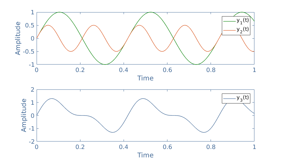
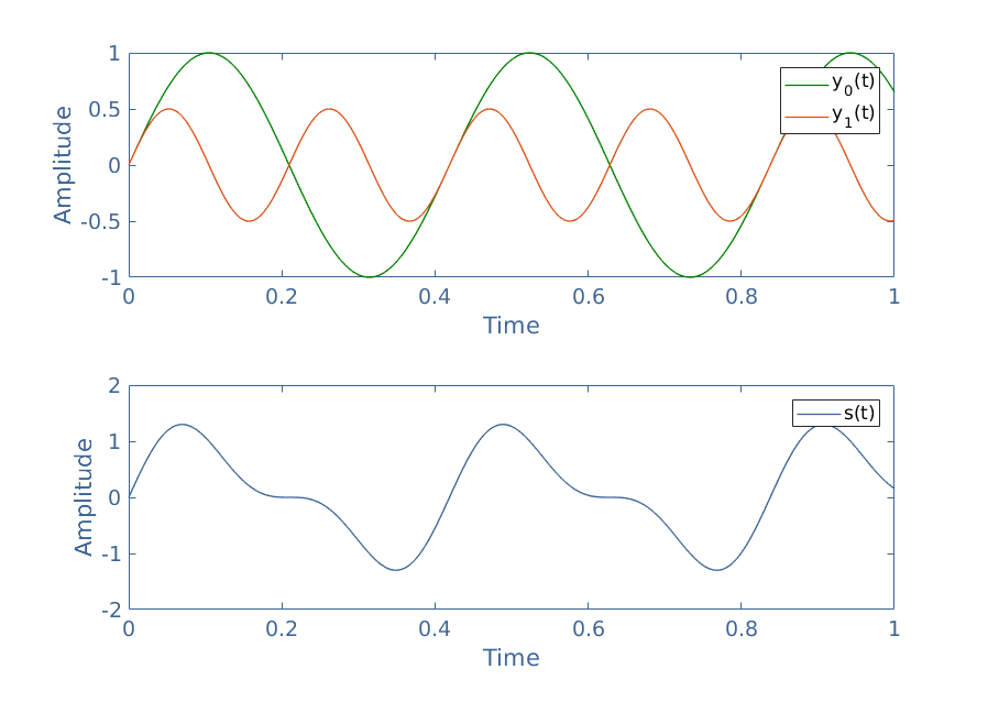
Consider a periodic signal s(t) which is a superposition of two sinusoidal waveforms called harmonics y0(t) and y1(t) which their frequencies and amplitudes satisfy ω1=2ω0; A0=2A1. Their expressions are therefore given by y0(t)=A0sin(ω0t) and y1(t)=A1sin(ω1t). Figure 1 illustrates the harmonics y0(t) and y1(t) separately from the resulting signal s(t) :
fig 1: Representation of a complex waveform along with its harmonics
In this example, y0(t) is called the fundamental harmonic and y1(t) the first harmonic. The fundamental harmonic is the signal with the lower frequency and it gives the periodicity of the resulting signal s(t): we can indeed see that ω0=ωS.
Harmonics are therefore the “building” functions of a complex waveform, however, their frequencies are not random and always satisfy ω0=ωS, ω1=2ω0, and ω2=3ω0 if a second harmonic is present and so on … In the general case, the frequency of the nth harmonic satisfy the relation ωn=(n+1)×ω0.
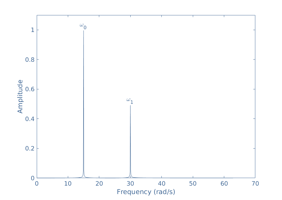
When given a particular complex waveform, one representation is very suitable and called the spectrum of the signal. This representation consists of plotting the amplitudes of each harmonic as a function of the frequency and can be computed by a numerical program such as Python or MatLab :
fig 2: Frequency spectrum of s(t)
Examining the spectrum of s(t), it is clear to visualize that the fundamental signal has a frequency f0=15/2π=2.4 Hz and an amplitude A0=1 (V or A for example) while the first harmonic has a frequency of 2f0=4.8 Hz and an amplitude A1=0.5.
Spectral analysis
Plotting a spectrum such as shown in Figure 2 is based on a mathematical tool known as the Fourier’s series. It is in the early 19th-century that this method is developed by the French scientist Joseph Fourier and it is still nowadays one of the major tools of signal analysis.
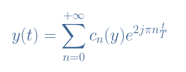
This method is based on the observation that any periodic signal y(t) is, in fact, an infinite sum (a series) of harmonics which amplitudes and phases can be computed. The same observation can be written as a mathematical equation :
eq 1: Decomposition of a periodic signal as a Fourier series
The complex exponential term is simply the complex form to write the harmonics (refer to the tutorial Complex Numbers). The integer n refers to the nth harmonic and T is the periodicity of y(t).
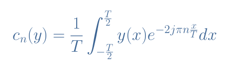
The coefficients cn(y) are called Fourier coefficients of the function y(t) and are determined by the following relation :
eq 2: Fourier coefficients
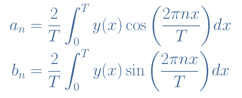
It is common to split the coefficients cn into two coefficients an and bn, which for real functions are given by :
eq 3: Simplified Fourier coefficients for real functions
This method to determine the Fourier decomposition of any periodic signal, therefore giving the spectrum such as presented in Figure 2 is also known as Fourier Transform (FT) which is an extension of the same method for non-periodic signals.
Two cases need to be considered separately in order to proceed to an FT of a periodic signal and explained in the following subsections.
Known signal
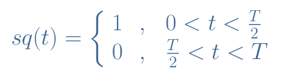
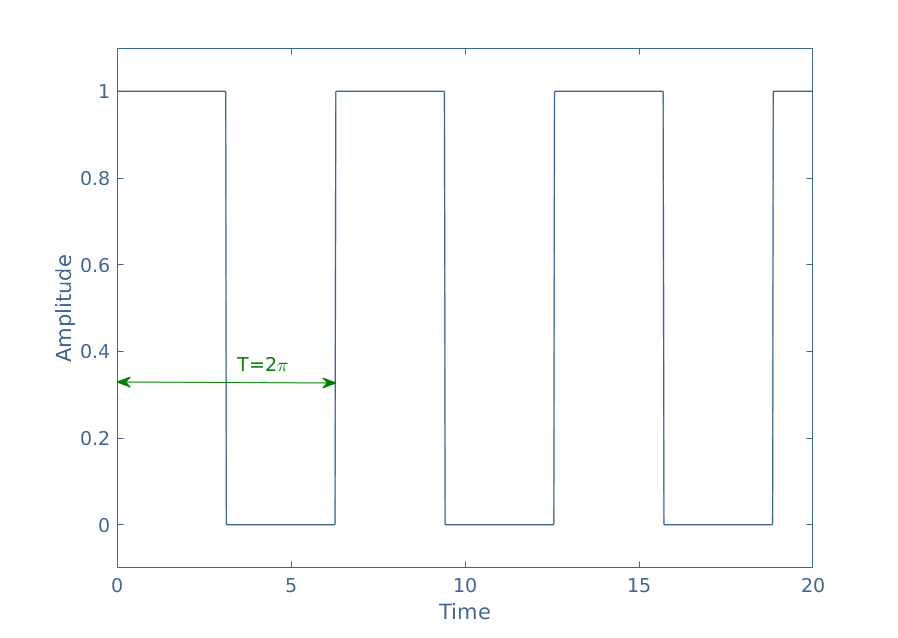
The first case is if the signal to be decomposed has a known analytical expression. Consider for example a square signal sq(t) with a periodicity of T. Its expression is known through the following definition :
Figure 3 represents a square signal of period T=2π over a few periods :
fig 3: Illustration of the square signal
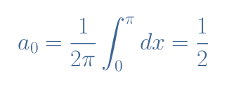
First of all, we determine the expression of the term a0 :
This coefficient represents the average value of the signal: y(t) and is indeed equal to 1 for half of the time and 0 otherwise. Note that since sin(0)=0, the term b0 is equal to zero.
When developing the expression of an for n>0, we realize that these coefficients are proportional to sin(nx) evaluated between 0 and π, which is alway equal to 0, therefore (an)n>0=0.
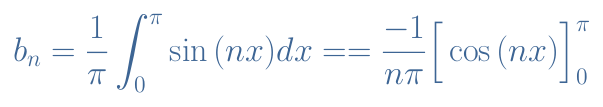
Finally, we determine the general expression for the coefficients bn for n>0:
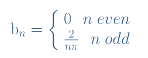
When evaluated between 0 and π, the term cos(nx) is equal to -2 if n is odd and 0 if n is even. The final expression of (bn)n>0 is therefore given by:
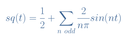
Each coefficient bn corresponds to the amplitude of the harmonic sin(nt). From the expressions of a0 and bn, we can, therefore, give the full Fourier development of the square signal sq(t):
eq 4: Fourier development of the square signal of period 2π
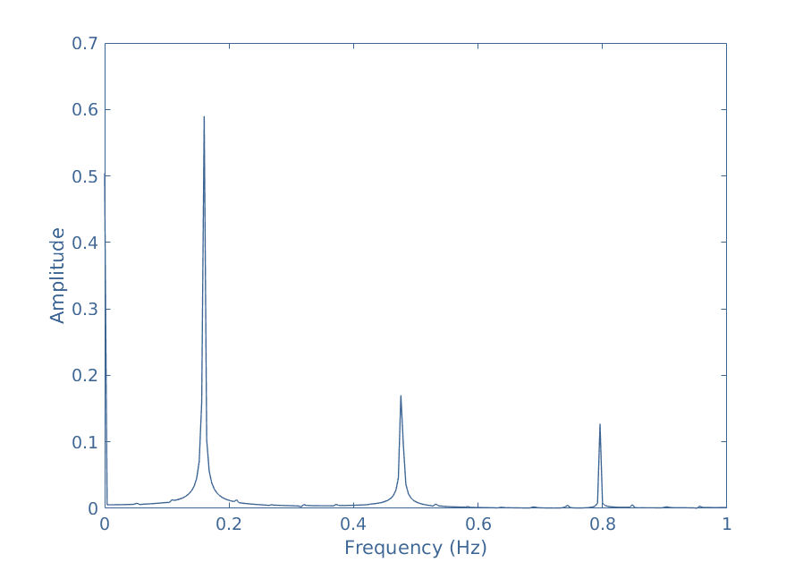
From Equation 4 we can plot a part of the spectrum of sq(t) shown in the following Figure 4:
fig 4: Spectrum of the square signal sq(t)
For this signal, only the odd harmonics are present, their amplitude is given by 2/nπ and frequency by n/2π. Note that the average value is also present in the spectrum for a frequency of 0 Hz. Since a square signal presents an infinite number of harmonics, the spectrum is of course shown only until a certain frequency.
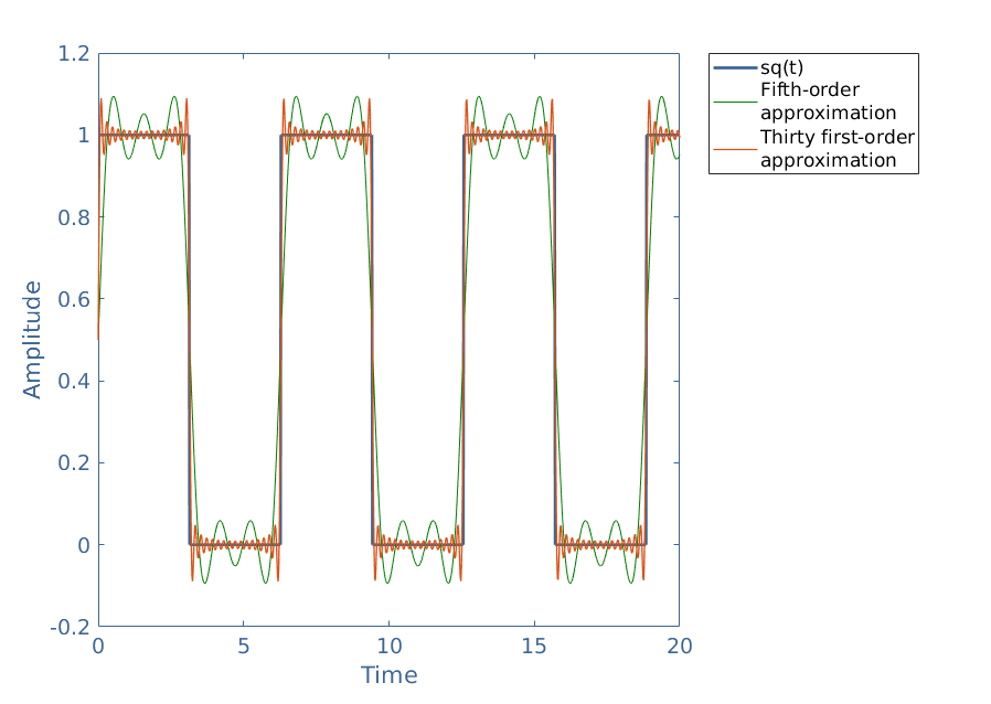
When generating a square signal with a function generator for example, only a finite number of harmonics is taken in order to build the waveform. We say that the signal is generated using harmonics until the fifth-order if we use the harmonics 1, 2, 3, 4 and 5 for example, the order gives the degree of accuracy regarding the shape:
fig 5: Illustration of two approximations of the square signal using harmonic decomposition
When the order of the approximation increases, we can pinpoint that an overshoot appears around the discontinuity jump (where the signal brutally alternates from 0 to 1 or from 1 to 0). This is known as the Gibbs phenomenon and appears for every signal where a discontinuity jump is present.
Unknown signal
Let’s reconsider the example given in the presentation section and give an explanation of how the numerical program determines the Fourier decomposition of s(t). In Figure 1 we can measure the periodicity of s(t) to be T=0.42 s.
The first coefficient c0(y) is easy to determine and equal in our example to 0 because the integral over a period of a periodic signal that is symmetrical around the horizontal axis is always equal to 0. Indeed, this first coefficient is always related to a DC quantity and therefore an average value, which is not present in our case.
When the expression of the function s(t) is known, the coefficients cn can be analytically computed such as shown in the previous subsection. However, for an unknown function s(t), the coefficients an(y) and bn(y) for n>0 are determined by numerically by computing the area between -T/2 and T/2 (or 0 and T) under the curve of the functions s(t)cos(2πnt/T) and s(t)sin(2πnt/T).
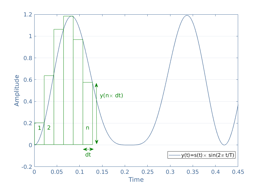
This can be done by many methods, one of the easiest to implement and understand is the rectangle method which idea is represented in Figure 6 for the function s(t)sin(2πt/T):
fig 6: Illustration of the rectangle method
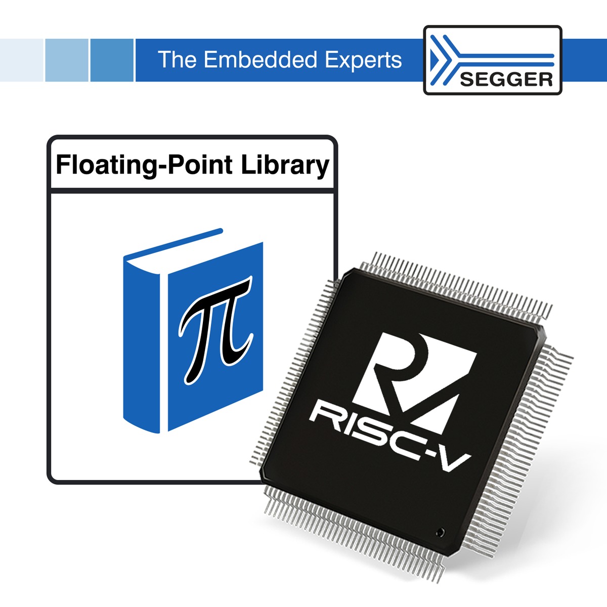
As shown in Figure5, this method consists of approximating the integral of the curve by summing the area of small rectangles of width dt and height y(n×dt) with n being the index of the rectangle considered.
The period T of the signal y(t) is subdivided in N rectangles such as N×dt=T. When dt is small enough, the sum of the area of the rectangles is approximately equal to the integral of y(t) over a period:
It is worth to mention that more precise methods exist in order to converge better to an exact result, such as for example by choosing another shape than rectangles to follow the curve more accurately.
Conclusion
As presented in the first section of this tutorial, harmonics are elementary sine waveforms that form any periodic signal. Some complex waveforms can have a finite number of harmonics and others have an infinite number, such as the square signal presented later in the tutorial.
The frequencies of harmonics are always an integer multipleof thefundamental frequency of the complex signal. Their amplitude usually decreases towards high frequencies and can be determined by the Fourier decomposition.
The spectrum representation is the most convenient way to highlight the harmonics of a signal, it is computed thanks to the Fourier decomposition presented in the second section. The decomposition can be analytical if an expression of the complex waveform is known or numerical if the signal is unknown.
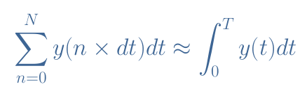
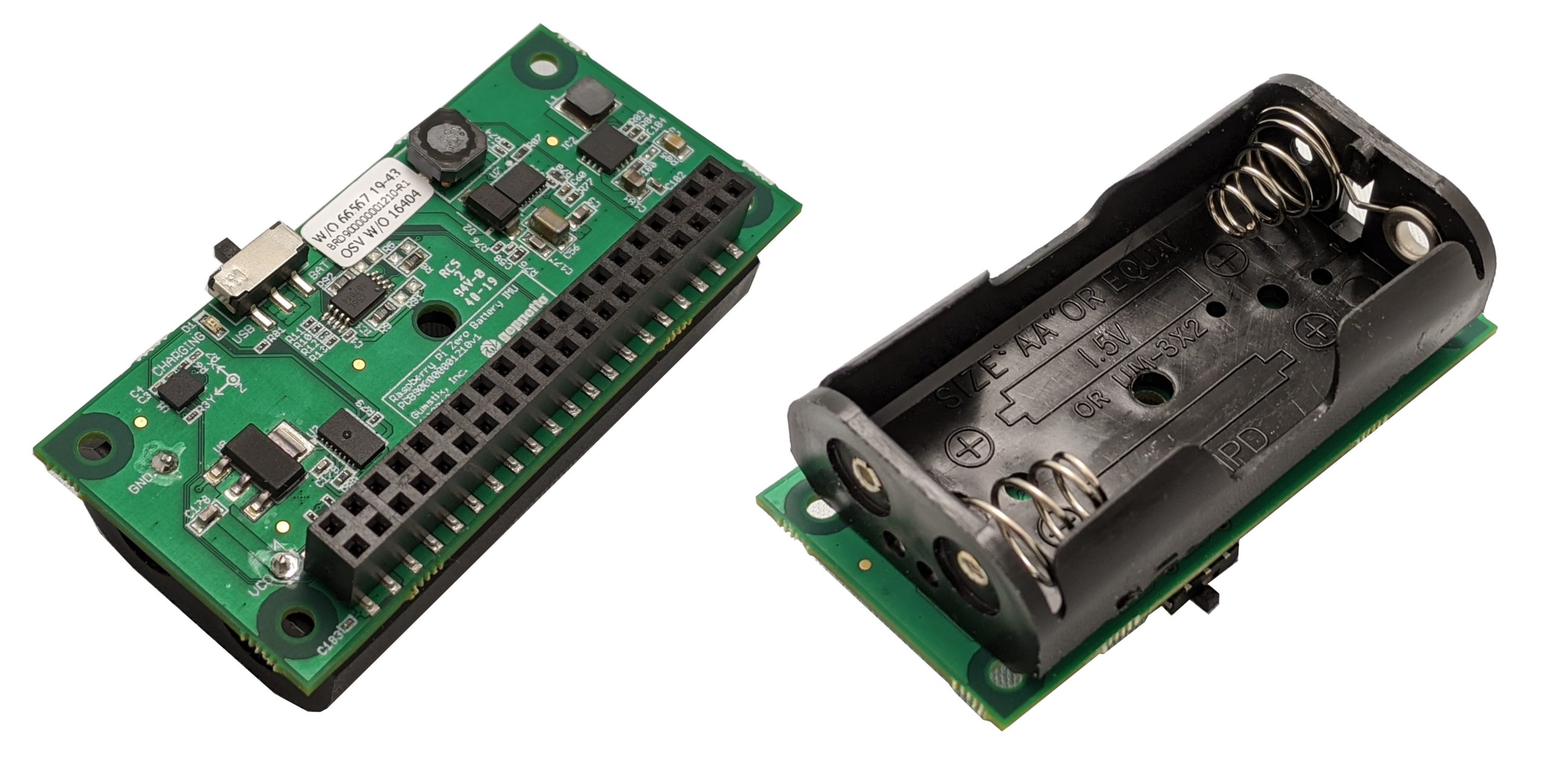
Take your Raspberry Pi Zero anywhere with the Raspberry Pi Zero Battery IMU. Add a camera to enable totally wireless video streaming. Charge the two AA batteries by plugging in the Pi Zero to a micro-USB connector.
Details:
Memory (256Kb I2C Serial Board EEPROM)
CAT24C256 Series 256 kbit (32 K x 8) 1.8-5.5V I2C CMOS Serial EEPROM – TSSOP-8
Complete fast charger controller for single, 2-, 3- or 4-series cell NiMH/NiCd batteries.
Designed by Gumstix in Geppetto, the Raspberry Pi Zero Battery IMU board allows you to take your Raspberry Pi Zero anywhere. Simply pop in two rechargeable NiMH or NiCd batteries into the holder and you’re ready to go anywhere with you Raspberry Pi Zero. Charging the batteries is as easy as plugging in your Raspberry Pi Zero using a USB cable, as per usual. With the onboard Bosch BMI160 3-axis accelerometer and 3-axis gyroscope, you can easily track motion. Add a camera to enable totally wireless video streaming.
The Gumstix Raspberry Pi Zero Battery IMU is available now for $50 Pre-Order. More information may be found at the Gumstix product and shopping page.
Comprehensive array of arithmetic functions, hand-coded & optimized in assembly language.
SEGGER‘s stand-alone Floating-Point Library has now been extended to include an assembly-optimized variant for RISC-V implementations. The library contains a complete set of high level mathematical functions that have been written in C, and uses advanced algorithms to maximize performance levels.
All of the functionality is fully verified, for both single and double precision operations. The RISC-V variant, like the existing variant for ARM, is optimized for both high-speed operation and small code size. The balance between size and speed can be configured at library build time.
The SEGGER Floating-Point Library for RISC-V is much smaller than equivalent open-source libraries currently available, while achieving up to 100 times the performance on some key operations. This library is also a part of the company’s Runtime Library, which is already included in the widely-used Embedded Studio platform.
For details on what makes a well thought-out runtime library different from a conventional runtime library, refer to the SEGGER Runtime Library webpage: https://www.segger.com/runtime-library
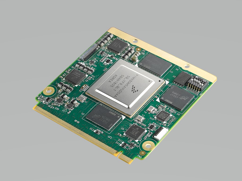
Advantech, a global leader in the embedded computing market, is pleased to announce its first NXP i.MX8 product: ROM-7720, an Arm-based Qseven module powered by the NXP Arm® CortexTM-A72 i.MX8 high-performance processor. ROM-7720 supports 4K resolution via HDMI 2.0 with H.265 H264 hardware accelerator engines for video decoding and additional GPU for image processing. Using OpenVX, it is ideal for AI, machine vision, and big data processing and analytics applications in the IoT era.
Powerful Computing Performance for Visual Processing
ROM-7720 adopts NXP i.MX8 Quad Max SoC, which integrates two CortexTM-A72, four Cortex-A53 and two Cortex-M4F processor cores and the Vivante GC7000XS/VX graphics engine, which supports OpenGL ES, OpenCL and OpenVL (vision) SDK for developing images, data processing, and analytics applications. ROM-7720 supports display output with HDMI2.0 (3840 x 2160 @60Hz), dual 24bit LVDS for multiple displays, and 2 + 4 lanes MIPI-CSI camera input. It supports a high resolution display and meets the camera requirements of different machine vision applications.
New High Speed Interface for AI and Machine Vision Applications
ROM-7720 offers new high speed I/O, including USB 3.0, PCIe 3.0 and SATA 3.0. It provides efficient interfaces for extending peripheral devices, such as the SSD, 5G cellular card, and FPGA IC to empower new AI and machine vision development.
Advantech will support allied, industrial and modular (AIM) frameworks for Linux applications that help accelerate software development via flexible, long-term support. AIM-Linux services offer verified embedded OS platforms and industrial-focused apps and SDKs through which users can easily select the embedded software tools they need to focus on their vertical software development.
Onboard QSPI Flash 256MB, eMMC Flash 8GB, boot selection from SPI/MMC/SD or SATA
3 USB 3.0 with OTG, 4K HDMI, Dual MIPI Camera
Multi OS support in Yocto Linux and Android
Advantech ROM-7720 is available now! Please contact an Advantech sales office or authorized channel partner to learn more about it. For more information on Advantech’s Arm computing products and services, visit risc.advantech.com now!
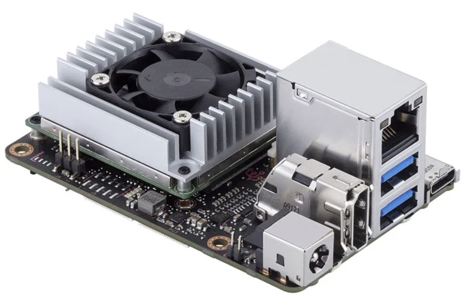
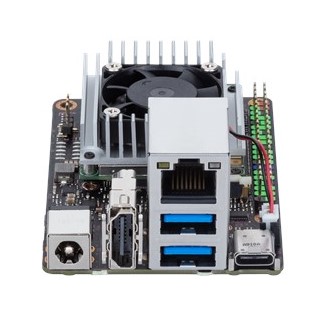
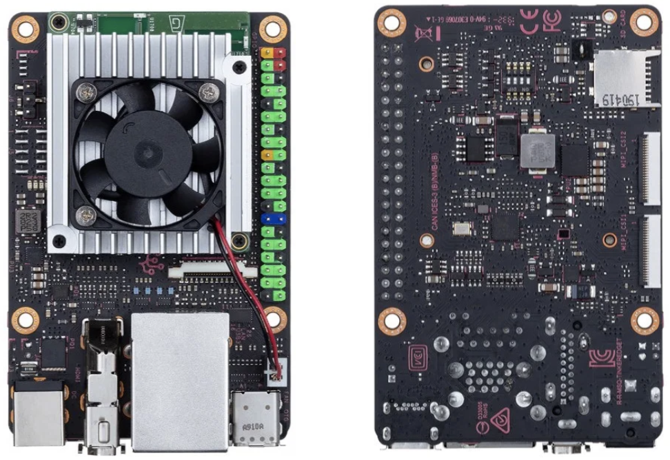
Tinker Edge T, is an SBC developed by ASUS that comes equipped with an i.MX8M and an Edge TPU, running the Debian-based Mendel OS Linux on a coral SOM module with a cross-platform OS flash tool that enables easy OS image flashing to SD cards and USB drives, enabling users to get their system up and running quickly.
It seems to be an open-spec board, much like Asus’ earlier released Rockchip RK3288-based Tinker Board S, and it is probably planned to serve as Asus’ equivalent of Google’s Coral Dev Board. The board offers two faster-10Gbps USB 3.2 Gen1 ports, a USB 3.2 Type-C OTG port with both power and peripheral support while the Coral Dev Board has USB 3.0 host, USB 3.0 Type-C power, and micro-USB serial console ports. The Tinker Edge T lacks the Coral Dev Board’s audio features: 3.5mm audio jack, two digital PDM mics, and stereo speaker header, but it comes with three PWM, a set of I2S pins on the Raspberry Pi-like 40-pin expansion header, and supplies dual 4-lane, MIPI-CSI2 interfaces.
The Asus Tinker Edge T is also designed such that it delivers 45 watts of power with a DC head power supply, enabling stable system operation, and full I/O performance, even with multiple connected devices. This is a significant feature as the power design of most SBC’s including the Coral Dev Board is usually 5v, 3A.
Some of the specifications and features of the board as listed by Japanese retailer Physical Computing include:
NXP i.MX 8M SOC
GC7000 Lite (1GHz) GPU
Quad-core ARM A53 (1.5GHz), Coretex-M4 CPU
Dual-CH LPDDR4 1GB
Google Edge TPU Neural Network Processor
8GB eMMC with 1 x Micro SD (TF) card slot (push / pull) for storage
2 x MIPI 24-pin CSI-2
RTL8211F-CG Gbit LAN, 802.11 b / g / n / ac & Bluetooth 4.2
USB 3.2 Gen1 Type-A ports x 2, USB 3.2 Gen1 Type-C OTG port x 1
2-19V DC Power input
0 ~ 50 ℃ operating temperature range
0% to 85% RH
Mendel Linux OS
3.37 ”x 2.125” Size
I/0
– 1 x 40-pin headers include:
– up to 28 x GPIO pins
– 1 x SPI bus
– 2 x I2C bus
– 2 x UART
– 3 x PWM
– 1 x PCM / I2S
– 2 x 5V power pins
– 2 x 3.3V power pins
– 8 x ground pins
– 1 x Boot mode switch
– 1x 2-pin Reset header
– 1 x 2-pin DC Fan header
The product launch announcement mentioned the provision of a robust API and SDK that enables users to deploy machine-learning models, for applications like image classification and object detection, easily
No price information was provided in the announcement but the Tinker Edge T board is listed on Physical Computing for 21,600 JPY (about $200), and $168.35 on Provantage.
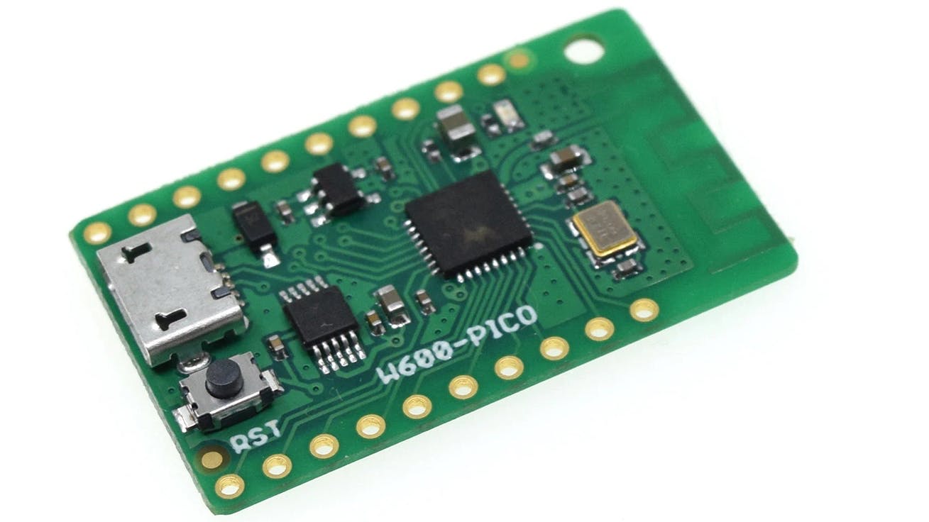
W600 – PICO is currently the most recent board released by Wemos. The company is responsible for boards like the D1 and D32. This board is based on a Winner Micro – W600 SoC. The first time users had the opportunity to work with the chip when Seeed released multiple boards starting from late 2018. None of these boards allowed users to utilize the features the chip had to offer ultimately.
The W600 is an Arm Cortex M3 with a clock speed of 80 MHz and 1 MB of Flash. The chip supports hardware cryptography and a 2.4 GHz Wi-Fi. Initially, the W600 has been hinted to take over the ESP8266, but it was never really adopted by the maker community, just like other similar boards. It stayed as a Wi-Fi-to-Serial bridge and had features that already existed in the ESP8226. Nevertheless, the W600 board is still appealing to some users because it houses an ARM core, unlike the ESP8226, which is based on the Xtensa cortex giving it some advantages when used in specific ways.
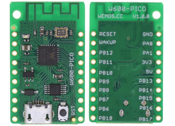
However, the new board is now changing things as it comes pre-loaded with the Micropython firmware on board. There is a micro USB port available as a source of power and for loading programs. It is connected using a CH340 USB – TTL chip. On both sides of the board, there are 10 pin headers. Some of these are the Wakeup, reset, +5V, and GND pins.
The W600 is an Arm Cortex-M3 running at 80MHz with 1MB of Flash on-chip as well as 2.4GHz WiFi support.
Board Specification
SoC – Winner Micro W600 Arm Cortex-M3 MCU @ 80MHz with 1MB Flash.
Wireless Connectivity – 2.4GHz 802.11 b/g/n Wi-Fi 4 up to 150 Mbps.
USB – 1x Micro USB port (via CH340 USB to TTL chip)
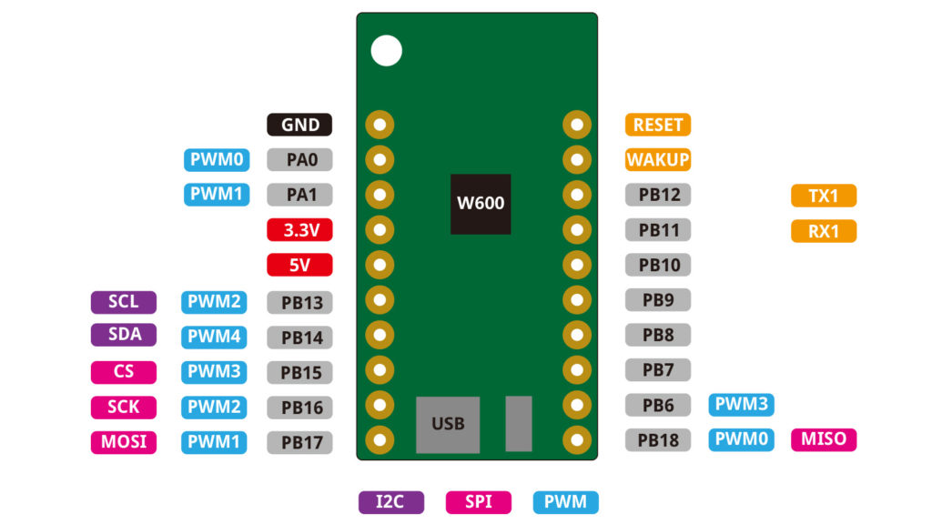
Expansion –
2x 10-pin headers with 15x GPIO
9x PWM.
1x I2C.
1x SPI
1x UART.
Wake Up.
Reset Pin
5V and 3.3V supply.
Power Supply – 5V via micro USB port.
Operating Voltage: 3.3V
Dimensions – 33.0mm by 20.3mm
Weight – 3g
Wemos has provided a wiki page with further information that might be needed. Detailed instructions for beginners on how to get started can be found here. There are also instructions for users who would like to reflash and updated the firmware. Tutorials are provided to help users learn how to use the on-chip RTC, networking, and Serial Peripheral Interface (SPI).
Furthermore, this new board is most likely the cheapest board Wemos has introduced into the community. It is currently being sold for $2.10 on Ali-Express. Although it is stated on the official Ali-express store has not been available again but it is available on some other stores here.
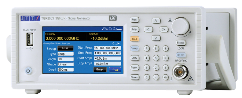
The TGR2050 Series provides exceptional performance with new touch screen operation for improved functionality to support research and development, test and service functions
Farnell, the Development Distributor, announced the availability of the TGR2050 series of next generation Radio Frequency (RF) signal generators from Aim-TTi. Electronic design and test engineers will benefit from the small footprint and lightweight design of the new-to-market TGR2050 Series, offering the best price/performance ratio in its class. These RF signal generators build upon Aim-TTi’s reputation for manufacturing high-quality and reliable products and are now available for same day despatch from Farnell.
The TGR2050 series includes TGR2051 and TGR2053 RF signal generators which provide exceptional performance with high signal purity, high frequency accuracy and stability, a large signal amplitude range, low phase noise and fast amplitude and/or frequency sweeps. Extensive and flexible analogue and digital modulation capabilities make these signal generators ideal for research and development, test and service work.
Both models also offer improved functionality with intuitive touch screen operation. Advanced remote-control connectivity accommodates sophisticated new automated systems and compatibility with Aim-TTi’s previous RF instruments, ensuring simple integration with existing systems.
Key features of the TGR2050 Series RF signal generators include:
High frequency accuracy and stability, high signal purity with excellent phase noise, output power levels of -127dBm to +13dBm, and flexible analogue and digital modulation capabilities.
A sweep function enabling signals of varying frequency and/or amplitude to test a full range of input conditions quickly and efficiently. Sweeps can be set to run in either direction, with linear or logarithmic spacing. Alternatively, list mode (accessible within the instrument or from remote interfaces) can be used to analyse the response at set frequencies and amplitude.
A TGR-U01 option adding an extensive range of digital modulations: FSK, GFSK, MSK, GMSK, HMSK, 3FSK, 4FSK, PSK, ASK and OOK. Built in NRZ patterns include Square wave, 7, 9, 11 and 15-bit PRBS. Digital modulation capabilities also include advanced filtering. External digital modulation signals can be applied to the carrier waveform via the MOD in/out on the rear panel.
James McGregor, Global Head of Test and Tools for Farnell says: “The new TGR2050 Series of RF signal generators from Aim-TTi is an excellent addition to Farnell’s market-leading Test range. This series delivers exceptional performance at a class-leading price point. In 2019, Farnell invested over £4 million in the Test category and as we begin 2020 we remain committed to further increasing the breadth of our portfolio, to ensure electronic design professionals have access to the latest and most advanced test and measurement technologies.”
Customers also benefit from Farnell’s in-house test and measurement specialists who provide 24/5 technical support as well as access to free online resources, data sheets, application notes, videos and webinars.
Aim-TTi is a leading producer of innovative and cost-effective function generators, precision and RF instruments, including the PowerFlex, Multi-range and Precision Power Supplies.
The Aim-TTi TGR250 Series RF signal generators are available from Farnell in EMEA, Newark in North America and element14 in APAC.