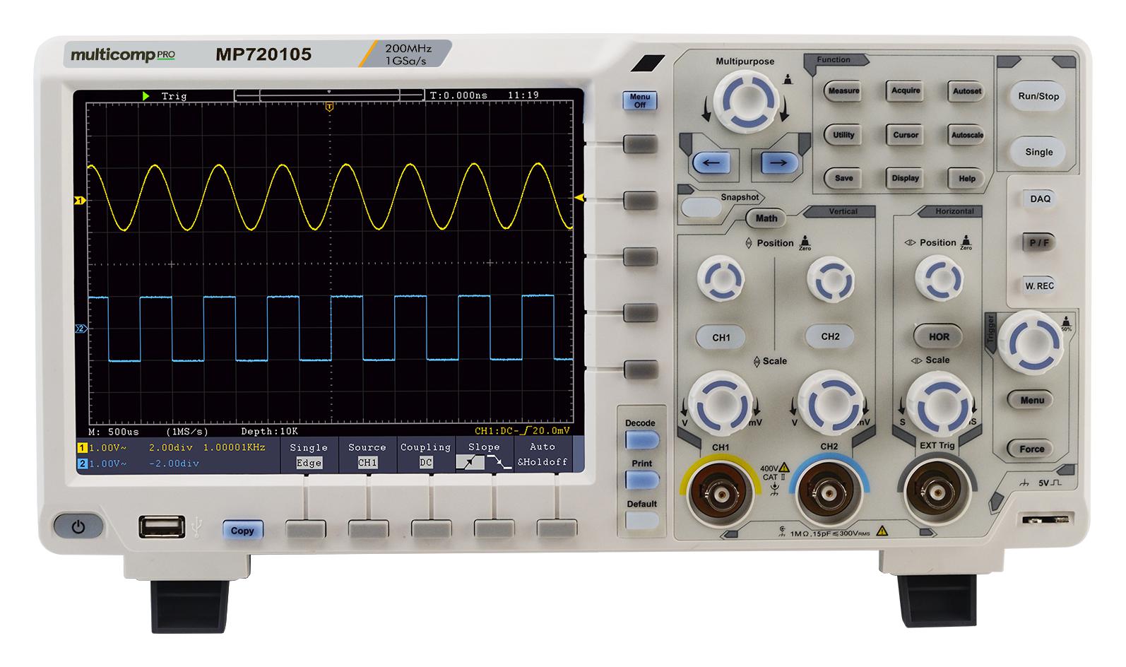
The MP720105 from Multicomp Pro is a newly launched 200MHz, 2-channel digital storage oscilloscope, featuring 1GS/s sampling rates, 8-bits vertical resolution, an 8″ colour LCD screen, and decoding kit (RS232, SPI, I2C, CAN trigger/decode).
Ultra-thin design, less space accommodation
Multi-interface integration – USB host, USB device, USB port for PictBridge, LAN, AUX
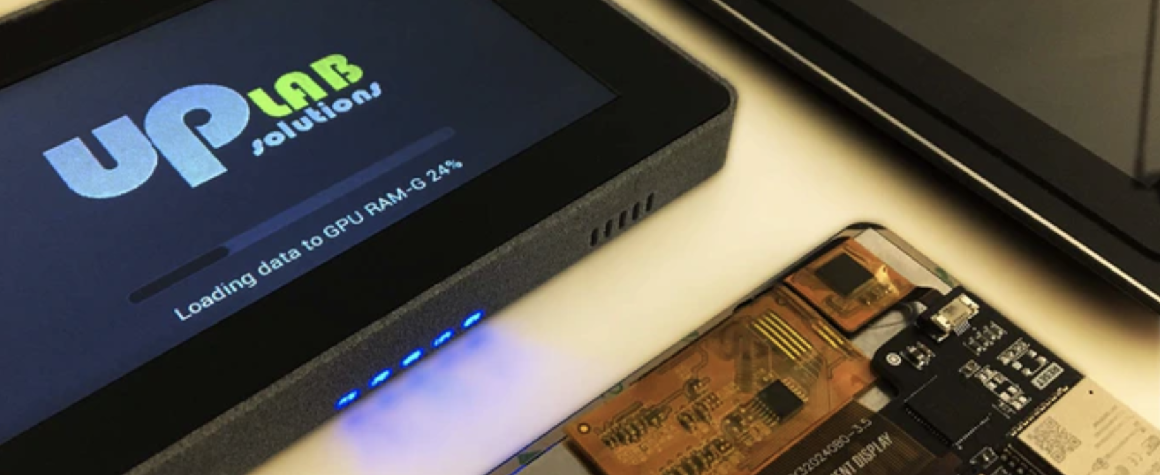
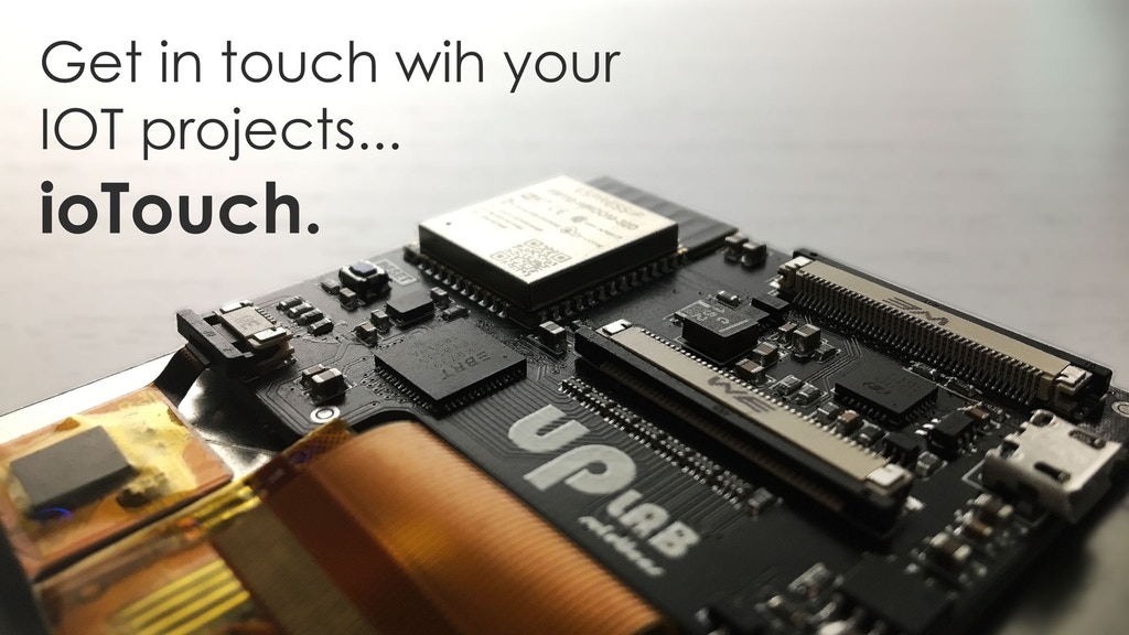
IoTouch is an ESP-32 based board with touchscreen capabilities. Its got an external embedded GPU interfaced with a 24 RGB TFT glass capacitive display. It is specially built for IoT applications due to its Bluetooth and WiFi features. If you need a wireless device that has a good and intuitive HMI, IoTouch was made for you.
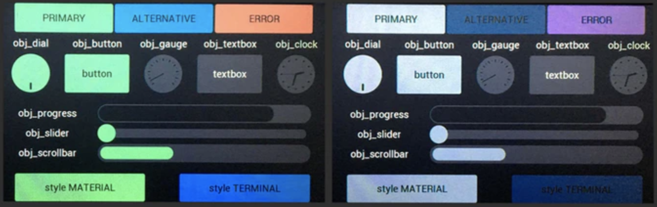
It’s pages and event-based framework allows you to make pages and transition between them smoothly. It uses a grid-layout and margins to assist in placing your objects on the screen without complex position or pixel calculations. Text buttons, sliders, progress bars, dial gauges, clocks, and other complex objects can be created with just one or two lines of code all with autonomous and graphical touch behavior.
Your application’s appearance or style (foreground, background, fonts e.t.c) can be declared using a clearly defined programming interface and applied globally without any change to your codebase.
IoTouch’s display consists of a capacitive touch screen with an oversized glass frame for an easy installation. It’s mountable with 3M 200MP adhesive and available in 3 different sizes and resolutions.
Some specification and features of the display include:
ESP32-WROOM with dual-core Xtensa® 32-bit LX6 MCU, 16MB flash
WIFi 802.11 b/g/n (802.11n up to 150 Mbps) 2.4 GHz ~ 2.5 GHz
Bluetooth v4.2 BR/EDR and BLE specification
FT813 EVE2 video engine co-processor with 1MB dedicate Graphic-RAM, 24bit RGB interface, capacitive touch engine, audio engine, and PWM backlight output.
A USB connector with UART transceiver for autonomous boot and very useful for monitor purposes.
Smart power management with an internal switch to power from 5V (USB /external on FFC) or a Battery with an enable pin.
Integrated dimmable LED driver to control the display backlight.
FFC connector to expose all ESP32 usable pin (except ones used by internal flash), USB, enable pin and FT813 audio output.
All in 47 x 57mm dimension enables you to use it from 3.5″ to 5.0″ displays.
According to Rocco Taurasi (the project creator), the project can be said to be 85% complete as the prototyping and testing of the hardware and firmware has been done with only some marginal bug-fix and Arduino/PlatformIO integration left on the firmware. Rocco also mentioned most parts of the project will be open-sourced after the development process.
A Kickstarter campaign has been launched for the project with diverse offerings and a total goal of 80,000€. Order fulfillments are planned for July 2020.
More information on the project and the Kickstarter campaign can be found on the Product’s page.
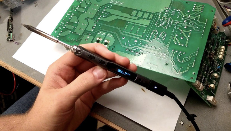
Okay, you’ve probably seen 20 different TS-100 hacks, for example, this, this and this but this improvement by Jan Henrik is on another level. For a soldering iron, the TS-100 seems to work quite well and its popularity, having only debuted 3 years ago, speaks volumes of this. It is relatively inexpensive, comes with temperature control, light-weight and portable, but a somewhat noticeable shortcoming is its inability to deliver as much power as most regular irons in the market, and while another version with higher power delivery, the TS-80 exists, it comes at a way higher price.
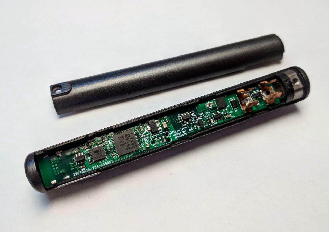
To improve this, Jan Henrik, developed an entirely new drop-in replacement PCB that converts the TS-100 into a USB-C PD powered soldering iron, making it absolutely awesome for soldering on the go, since you could power the iron from a normal USB-C PD power bank and also attain higher power since the USB-C PD is capped at 100W, which is 5 times the regular product!
Jan calls this upgrade the “Otter Iron” as he notes in a tweet, where he shared details of the project along with the cost slash features which puts his PCB + the TS-100 case + the TS-100 tip + some other parts combined, at a price cheaper than the original TS-100.
According to Jan, a bulk of the tasks around the project has been done, with the firmware all sorted, along with the GUI and temperature regulator. His demonstrations of the Iron handling a desoldering task with ease shows the functionalities are good, and its replicability has been confirmed by a few individuals who reported successfully building their own version of the Otter-Iron.
Demo
The project as most of Jan’s projects is properly documented on his Github page with some of the few remaining tasks highlighted. Some of the tasks include:
Current measurement
Better Fonts/UI for Display
PD-Profile cycling
Adding a barrel jack
Adding a grounding solution
The Project is already receiving contribution from several hobbyists like Timon who has already recreated the fuse holder for the TS-100, which was the only part missing from Jan’s PCB.
One caution so far is an earthing problem with USB-C’s when used with an ungrounded laptop adaptor. So it’s much safer to use a three-pronged charger or separate hooking to ground.
Regardless, this is great work from Jan Henrik. You can follow his progress and get the project files on the project’s Github page.
The beauty of capable computing is that aside from being cheap enough, it should also be good enough.
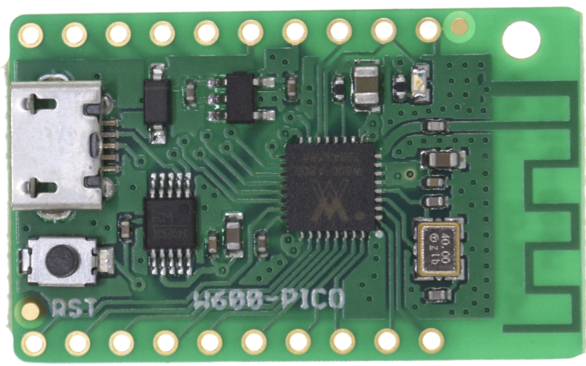
While we have seen some great WiFi IoT boards like Wemos D1 mini and Lolin32, there has not been anything like the newly launched W600-PICO board from Wemos. The new W600-PICO board, based on Winner MicroW600 Arm Cortex-M3 WiSoC, is the cheapest board ever from Wemos to come preloaded with a MicroPython firmware for just $2.10 + shipping.
Unlike the previous W600-based boards which have stayed as designed and probably been used as a WiFi-to-serial board only, the new W600-PICO seems to be a rather more interesting one, perhaps first viable competitor, for the nearly ubiquitous ESP8266-based boards due to its feature set and lower cost. The board which runs MicroPython out of the box and is built around an Arm Core might be preferred to the already existing Espressif-based boards, asides features, it also has a price point to match them with.
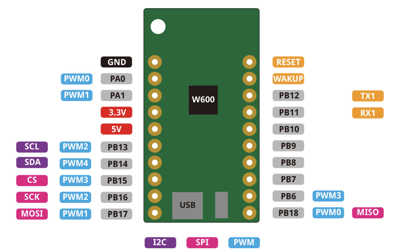
W600 Pinout
The W600-PICO board breaks out with two 10 pin headers: 9 x PWM, 15 x GPIO, 1 x UART, 1 x12C, 1 x SPI , Wake Up, Reset, + 5V , +3.3v and GND pins. Its other features include:
Wireless connectivity – 2.4GHz 802.11 b/g/n WiFi 4 up to 150 Mbps
SoC – Winner Micro W600 Arm Cortex-M3 MCU running @ 80MHz with 1 MB flash
Misc – Reset Button
USB – 1 x Micro USB port for power and programming which is connected using a CH340 USB to TTL chip
3.3V I/O voltage
Real Time Clock and hardware cryptography support
Power supply – 5V through the micro USB port.
Dimensions – 33 x 20.3 mm and
Weight – 3 grams
Coming preloaded with MicroPython, the toolchain problem people experience with previous W600-based boards will no longer exist. Users who purchased the board already seem to be satisfied with it as they affirm it is all good and that the Micropython works immediately.
To provide a means of learning about the board, Wemos has set up a Wiki page where more details about the mini WiFi board can be found, alongside instructions on how to re-flash the board and update the firmware. There are also codes that show how to get started with networking, RTC, I / Os and timers.
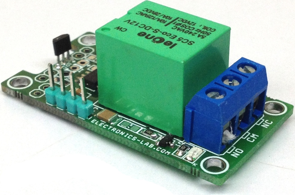
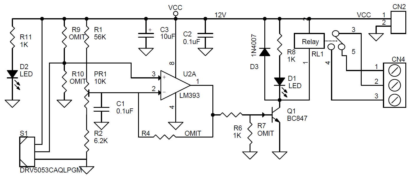
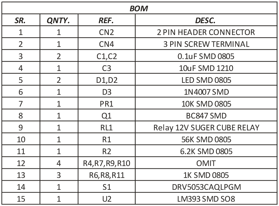
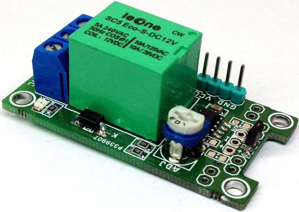
This is a hall sensor proximity sensor that can detect magnetic targets approaching the sensor, without physical contact with the target. This sensor also can be used to detect the distance range 0-4cm (0-40mm). The target distance can be adjusted using the onboard trimmer potentiometer. The project is built around DRV5053 magnetic field sensor and LM393 comparator. Relay provides normally open and normally closed operations and relay can drive AC and DC load, AC 230V/5Amps and DC 30V/5Amps. LED D1 indicates sensor operation, LED D2 is a power LED.
Proximity Distance Sensor using DRV5053 Hall effect Sensor – [Link]
Selecting the right communication protocol is an important part of any IoT project as not being able to communicate with the server/device cloud quickly takes away the “I” in IoT and could lead to the ultimate failure of the project. Several communication protocols exist, from WiFi and Zigbee to 2G, LTE, and even satellite communications, but each of them is usually plagued by one limitation or the other which makes them unsuitable for certain IoT use cases, with the major culprits usually being a tradeoff between range, power, and bandwidth. Semtech, however, demonstrating an understanding the future of IoT, saw a potential game-changer when they acquired France based Cycleo in 2012. Cycleo had developed a patented wireless communication technology called LoRa, which combined ultra-low power consumption with an effective long-range. Semtech leveraged on the power of the community via a consortium and transformed the technology into one of the key drivers of the current wave of digital transformation being instituted by IoT.
Introduction to LoRa – Send data between two Arduino using LoRa – [Link]
This is a hall sensor proximity sensor that can detect magnetic targets approaching the sensor, without physical contact with the target. This sensor also can be used to detect the distance range 0-4cm (0-40mm). The target distance can be adjusted using the onboard trimmer potentiometer. The project is built around DRV5053 magnetic field sensor and LM393 comparator. Relay provides normally open and normally closed operations and relay can drive AC and DC load, AC 230V/5Amps and DC 30V/5Amps. LED D1 indicates sensor operation, LED D2 is a power LED.
Selecting the right communication protocol is an important part of any IoT project as not being able to communicate with the server/device cloud quickly takes away the “I” in IoT and could lead to the ultimate failure of the project. Several communication protocols exist, from WiFi and Zigbee to 2G, LTE, and even satellite communications, but each of them is usually plagued by one limitation or the other which makes them unsuitable for certain IoT use cases, with the major culprits usually being a tradeoff between range, power, and bandwidth. Semtech, however, demonstrating an understanding the future of IoT, saw a potential game-changer when they acquired France based Cycleo in 2012. Cycleo had developed a patented wireless communication technology called LoRa, which combined ultra-low power consumption with an effective long-range. Semtech leveraged on the power of the community via a consortium and transformed the technology into one of the key drivers of the current wave of digital transformation being instituted by IoT.
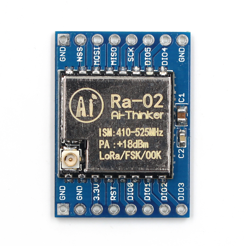
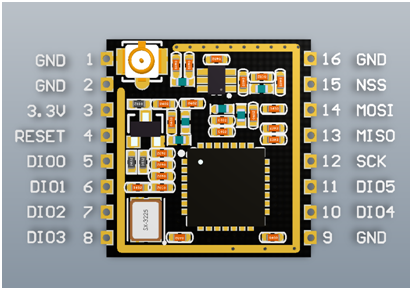
Ra-02 LoRa Module
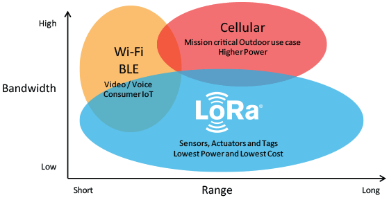
Using LoRa technology, devices can typically communicate over a range of 13- 20Km with the ability to go as far as 80KM in certain Line-of-sight setups, and as far as several 100s of KM from outer space as demonstrated by FOSSAT and Lacuna. This range achieved at a very low power which makes LoRa more suitable than other communication protocols, for remote, battery-powered IoT devices that are expected to run for months (or years) on a single battery charge.
LoRa compared with other networks
LoRa can be deployed in two major ways:
As a Peer to Peer Communication protocol
As a Low Power Wide Area Network
Peer to Peer communication allows two devices with LoRa radios to talk to each other in a manner similar to how two Bluetooth devices communicate, with the major difference being the fact that the range increases massively and less power is consumed.
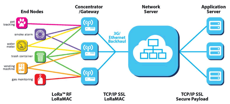
For deployment as a wide area network, LoRa works hand in hand with Protocols like LoRaWAN which its usually confused with. LoRaWAN is a high capacity, Long Range, open, Low Power Wide Area Network (LPWAN) standard, based on LoRa technology and designed for LoRa Powered IoT Solutions by the LoRa Alliance. The standard takes full advantage of all the features of the LoRa technology to deliver services including reliable message delivery, end to end security, location and multicast capabilities to users while ensuring the interoperability of the various LoRaWAN networks world-wide. This is the standard on which platforms like the things network are built.
LoRaWAN Network Architecture
While LoRa started with some level of uncertainty, it has grown into the communication means of choice for almost all types of IoT applications, even those who do not benefit from its low power consumption features due to their plugged-in nature. Several advancements like the outer-space based “Gateway” solution being deployed by FOSSAT and Lacuna is making it clear that it will have more impact on IoT than it currently does.
All of these features and advancements make LoRa an important topic for electronics enthusiasts and over the next two tutorials, we are going to build projects to demonstrate how LoRa can be used as the means of communication in your IoT projects. The first tutorial, which we will look today, will focus on using LoRa in a peer-to-peer communication mode, while the second tutorial will focus on LoRa as a Wide Area Network.
As a demonstration of LoRa being used for pair to pair communication, today’s project will feature two devices, one configured as a transmitter and the other, as a receiver. The transmitter will obtain temperature and humidity sensor from the environment using a DHT11 sensor connected to an Arduino Nano, and forward the data to the receiver via a Ra-02 LoRa module. For the receiver, we will use an ESP8266 Nodemcu development board with another Ra-02 LoRa Module. The temperature and humidity data sent by the transmitter will be received via the Ra-02 module and displayed on the Arduino IDE’s Serial Monitor.
Ra-02 LoRa Module Pinout
At the end of the tutorial, you would know how to send data between two devices using L0Ra and also how to interface an Arduino and ESP8266 based boards with a LoRa module.
Ready? Let’s go.
Required Components
The following components are required to build this project:
All of these components can be bought from the links attached. In place of the Arduino Nano, you can choose to use any other Arduino compatible development board. Just take note on how the change in board type affects other parts of the tutorial. The ESP8266 NodeMCU is also being used because we have a lot of them in stock. Feel free to use any other board. For the Ra-02 LoRa module, take note of the specified frequency when purchasing it to ensure it is legal to use that frequency in your country.
Schematics
As mentioned earlier, there are two sides to today’s project; the transmitter and the receiver, this means we will also have two schematics.
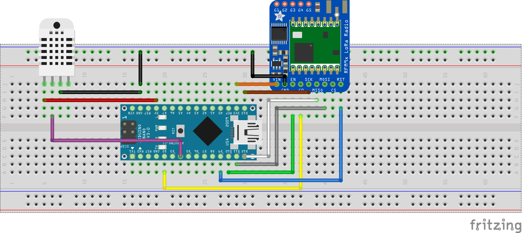
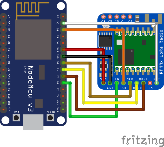
Transmitter Schematics
The transmitter comprises of the DHT11 and the Ra-02 LoRa module connected to the Arduino Nano. The output pin of the DHT11 is connected to a digital pin on the Nano while the Ra-02 is connected to SPI pins of the Nano. Connect the components as shown in the schematics below;
Schematics for Transmitter
To make the connection easy to follow, a pin-pin description is provided below;
Go over the receiver connections also to be sure everything is as it should be.
With both schematics implemented either on a breadboard or on a protoboard, we are now ready to write the code for the project.
Code
As mentioned during the introduction, the goal for today’s project is to send data between two devices (One configured as a transmitter and the other as a receiver) using LoRa. Thus, just like we did with the schematics, we will also split the code into two: Transmitter Code and Receiver Code.
Transmitter Code
The idea behind the code for the transmitter is simple. We obtain the environment’s temperature and humidity data using the DHT11 temperature and humidity sensor and broadcast the data over LoRa to our receiver with an Identity key which ensures the data is only delivered to our receiver.
To reduce the amount of work required to develop the code for our transmitter, we will use a couple of libraries including; the well built LoRa library by Sandeep Mistry along with the DHT library from Adafruit. The LoRa Library comes with a number of functions that make it easy to send and receive data with the LoRa module, while the DHT library makes it easy to interact and extract readings from the DHT11 sensor. Both libraries can be installed via the Arduino Library Manager or downloaded and installed via the links attached to them.
The code for the transmitter is based on the LoRa Sender example located in the LoRa Library, with slight modifications like the addition of a sync word which ensures only the designated receiver with the key receives the message.
To do a quick breakdown of the code, we start by including the libraries that will be used.
Next, we declare the pins of the Arduino to which the DHT is connected, specify the type of DHT we are using, and create an instance of the DHT library using both parameters.
#define DHTPIN D4 // what digital pin we're connected to
#define DHTTYPE DHT11 // select dht type as DHT 11 or DHT22
DHT dht(DHTPIN, DHTTYPE);
Next, we create a variable called “counter” which will be used to track the number of messages that have been sent to track if it was all delivered or some were lost.
int counter = 0;
With that done, we move to the void setup() function. We start the function by initializing serial communication, so we can use the Serial Monitor for debugging purposes.
void setup() {
Serial.begin(9600);
while (!Serial);
Serial.println("LoRa Sender");
Next, we initialize the DHT as well as the LoRa module specifying the frequency as 868MHz since that is the ISM frequency band supported by my LoRa radio and allowed in my country. If the initialization of the LoRa module fails, the code is suspended in a perpetual while loop, but if successful, we wrap up the void setup() function by setting a unique communication key (Syncword) and also set the power of the Lora radio to the maximum.
dht.begin(); //initialise DHT11
if (!LoRa.begin(868E6)) {
Serial.println("Starting LoRa failed!");
while (1);
}
LoRa.setSyncWord(0xF3);
LoRa.setTxPower(20);
}
Ensure the frequency you enter corresponds to that of your LoRa module and also be sure it is lawful to use that particular frequency for a project like this.
Up next, is the void loop() function. We start the function by obtaining temperature and humidity data from the environment using the DHT11 and storing them in variable T and H respectively. If the reading fails, we display a fail message and return.
void loop()
{
float h = dht.readHumidity();
float t = dht.readTemperature();
if (isnan(h) || isnan(t)) {
Serial.println(F("Failed to read from DHT sensor!"));
return;
}
Next, we use the LoRa.beginPacket() function to indicate the beginning of a packet, print the temperature and humidity data as part of the packet, along with the counter variable so we can keep track of the messages. then use the LoRa.endPacket() function to indicate the end of the packet and send broadcast it to the receiver.
Increment the counter and delay for 5000ms to give the module some time before the next data is sent. This goes on and on in the loop() continuously streaming temperature and humidity data from the environment to the LoRa Receiver.
counter++;
delay(5000);
}
The complete code for the LoRa transmitter is provided below and also attached under the download section.
#include <SPI.h>
#include <LoRa.h>
#include <DHT.h>
#define DHTPIN D4                                                           // what digital pin we're connected to
#define DHTTYPE DHT11                                                       // select dht type as DHT 11 or DHT22
DHT dht(DHTPIN, DHTTYPE);
int counter = 0;
void setup() {
  Serial.begin(9600);
  while (!Serial);

  Serial.println("LoRa Sender");
  dht.begin();     //initialise DHT11

  if (!LoRa.begin(868E6)) {
    Serial.println("Starting LoRa failed!");
    while (1);
  }
  LoRa.setSyncWord(0xF3);
  LoRa.setTxPower(20);
}
void loop()
{
  float h = dht.readHumidity();
  float t = dht.readTemperature();
  if (isnan(h) || isnan(t)) {
    Serial.println(F("Failed to read from DHT sensor!"));
    return;
  }
Serial.print("Sending packet: ");
Serial.println(counter);
// send packet
LoRa.beginPacket();
LoRa.print("Data:");
LoRa.print(counter);
LoRa.print("> ");
LoRa.print("Temperature: ");
LoRa.print(t);
LoRa.print(" ");
LoRa.print("humidity");
LoRa.print(h);
LoRa.endPacket();
 counter++;

  delay(5000);
}
Receiver Code
For the receiver, our goal is simply to capture the packet being sent by the transmitter and display it on the serial monitor. To reduce the code complexity, we will use the same LoRa library we used in the transmitter sketch. To do a quick run-through of the code, we start, as always, by including the libraries that will be used.
#include <SPI.h>
#include <LoRa.h>
Next, we define the pins of the Nodemcu to which the NSS, RST and DIO0 pins of the LoRa module are connected. You will notice we didn’t do this for the transmitter sketch? this is because we used the predefined Library’s predefined pins which are usable on the Arduino Nano but not so on the ESP.
//define the pins used by the transceiver module
#define ss D8
#define rst D1
#define dio0 D2
Next, we move to the void setup() function. We start by initializing the serial communication so we can use the Serial Monitor to view incoming data from the receiver.
void setup() {
  //initialize Serial Monitor
  Serial.begin(9600);
  while (!Serial);
  Serial.println("LoRa Receiver");
Next, setup the LoRa module by using the setPins() command to inform the library of the pin configuration to be used.
Next, we initialize LoRa communication with the begin() command. just like we did for the transmitter, ensure that the frequency you use as the argument for the begin() function should be that of your radio and lawful to use it in your country.
//replace the LoRa.begin(---E-) argument with your location's frequency
//433E6 for Asia
//866E6 for Europe/Africa
//915E6 for North America
if(!LoRa.begin(868E6)) {
Serial.println(".");
while (1);
}
To wrap up the void setup() function, we set the sync word to match that of the transmitter and we print a message on the serial monitor to indicate everything that setup is complete.
// Change sync word (0xF3) to match the receiver
// The sync word assures you don't get LoRa messages from other LoRa transceivers
// ranges from 0-0xFF
LoRa.setSyncWord(0xF3);
Serial.println("LoRa Initializing Complete!");
}
Next, we write the loop() function. We start the function by creating a variable to hold the received data and the size of the packet received which will be zero/false if no packet is received.
void loop()
{
String LoRaData;
int packetSize = LoRa.parsePacket();
Next, we use an “if” statement to check if a packet has been received, if yes, the data is read using the LoRa.readString() function and stored in the variable we created earlier.
if (packetSize)
{
// received a packet
Serial.print("Received packet '");
// read packet
while (LoRa.available())
{
LoRaData = LoRa.readString();
The read data is then displayed on the serial monitor along with the RSSI which is an indication of the signal strength and may be useful for debugging your transmission power.
Serial.print(LoRaData);
}
// print RSSI of packet
Serial.print("' with RSSI ");
Serial.println(LoRa.packetRssi());
}
}
The complete code for the transmitter is provided below and also attached under the download section.
#include <SPI.h>
#include <LoRa.h>
//define the pins used by the transceiver module
#define ss D8
#define rst D1
#define dio0 D2
void setup() {
//initialize Serial Monitor
Serial.begin(9600);
while (!Serial);
Serial.println("LoRa Receiver");
//setup LoRa transceiver module
LoRa.setPins(ss, rst, dio0);
//replace the LoRa.begin(---E-) argument with your location's frequency
  //433E6 for Asia
  //866E6 for Europe/Africa
  //915E6 for North America
  if(!LoRa.begin(868E6)) {
    Serial.println(".");
    while (1);
  }
// Change sync word (0xF3) to match the receiver
// The sync word assures you don't get LoRa messages from other LoRa transceivers
// ranges from 0-0xFF
LoRa.setSyncWord(0xF3);
Serial.println("LoRa Initializing OK!");
}
void loop()
{

  String LoRaData;
  int packetSize = LoRa.parsePacket();
if (packetSize)
{
  // received a packet
  Serial.print("Received packet '");

  // read packet
  while (LoRa.available())
  {
    LoRaData = LoRa.readString();
     Serial.print(LoRaData);
    }

    // print RSSI of packet
    Serial.print("' with RSSI ");
    Serial.println(LoRa.packetRssi());

   }
}
Demo
Connect the Arduino Nano to your computer and upload the transmitter sketch to it. Ensure to select the right board type and comport before uploading. After that, connect the Nodemcu too and upload the receiver sketch to it. Ensure to also switch the board type and select the right com port.
After uploading the sketches, you can decide to leave both devices connected to your computer or disconnect the transmitter device and power it using a power bank or battery leaving just the receiver. With the receiver still connected to your computer, open the serial monitor. You should see the temperature and humidity data from the transmitter being displayed on the Serial Monitor.
That’s it!
While today’s tutorial was a demonstration of peer-peer LoRa communication, the main joy of IoT is when you can get the data to server/device cloud and perform analysis that could lead to the extraction of value-adding insights as such, we will create a second part to this tutorial which will show how to get the data being received to the cloud.
Analog Devices’ controllers enable full functional safety if one of the batteries fail by forcing the other battery to take over
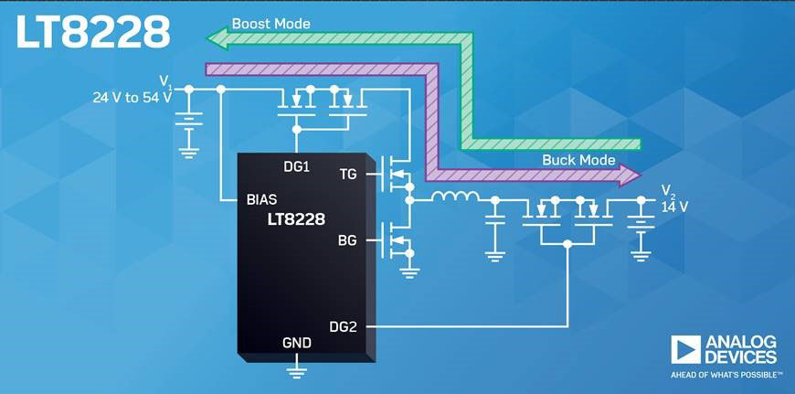
Analog Devices’ LT8228 100 V bidirectional buck or boost DC/DC controllers provide sustainable power in hybrid and electric vehicle (EV) critical non-drive train subsystems by controlling 48 V and 12 V batteries with bidirectional capabilities allowing for power source redundancy. These controllers also enable full functional safety if one of the batteries fails by forcing the other battery to take over allowing the vehicle to function properly, avoiding potential catastrophic results.
Features
Automatically determines the direction of power flow or the direction can be externally controlled
Provides a step-down output voltage when in buck mode or a step-up output voltage when in boost mode
Input and output voltage can be set as high as 100 V
Two error amplifiers, one for boost mode and the other for buck mode, with separate compensation pins
38-lead TSSOP package
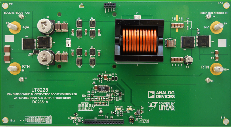
The LT8228 automatically determines the direction of power flow, or the direction can be externally controlled. Input and output protection MOSFETs protect against negative voltages, control inrush currents, and provide isolation between terminals under fault conditions such as shorts in the switching MOSFETs. In step-down mode, protection MOSFETs prevent reverse current. In step-up mode, the same MOSFETs regulate the output inrush current and use an adjustable timer circuit breaker to protect themselves.
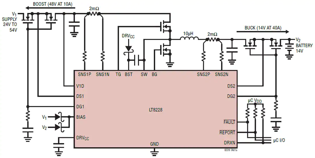
Simplified Schematic
The LT8228 implements bidirectional input and output current limiting as well as independent current monitoring. Masterless, fault-tolerant current-sharing allows LT8228 chips to work in parallel and to be added or subtracted while maintaining current sharing accuracy. Internal and external fault diagnostics and reporting are available via separate pins (FAULT and REPORT). Each LT8228 regulates to the average output current, thus eliminating the need for a master controller. When an individual LT8228 is disabled or in a fault condition, it stops contributing to the average bus, making the current sharing scheme fault-tolerant. The LT8228 sits in a 38-lead TSSOP package.
The LT8228 controller provides a step-down output voltage when in buck mode or a step-up output voltage when in boost mode. The input and output voltage can be set as high as 100 V. In applications such as battery backup systems, the bidirectional feature allows the battery to be charged from either a higher or lower voltage supply. When the supply is unavailable, the battery boosts or bucks power back to the supply.
To optimize transient response, the LT8228 has two error amplifiers, one for boost mode, the other for buck mode with separate compensation pins. The controller operates in discontinuous conduction mode when reverse inductor current is detected for light load conditions.
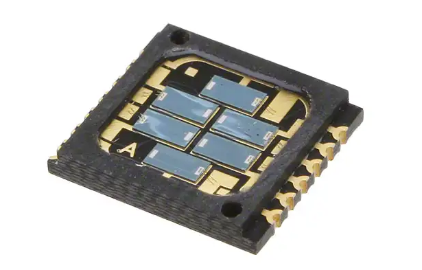
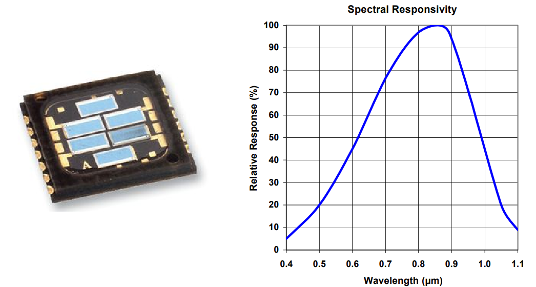
TT Electronics/Optek’s photodiode array features a high-temperature SMD chip carrier and low leakage current.
TT Electronics/Optek Technology’s OPR2100 device is a six-element photodiode that is designed to meet the needs of motor encoder applications. Designed specifically for industrial encoder applications, the OPR2100 features a high-temperature SMD chip carrier, a wide operating temperature range, and a low leakage current that can withstand extreme operating conditions. These devices have an opaque chip carrier that encloses six individual chips, which are mounted on isolated cathode contacts to allow external connection in any desired configuration. The opaque polyimide package shields the photodiodes from stray light and can withstand multiple exposures to the most demanding soldering conditions, while the gold-plated wraparound solder pads provide exceptional storage and wetting characteristics.