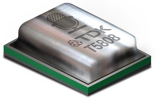
TDK Corporation introduces the world’s first MIPI Standard SoundWire® microphone for mobile, IoT and other consumer devices. This multimode microphone pushes the boundaries of digital microphone acoustic performance while providing advanced feature sets with very low power.
Highlights
T5808 is a 66 dB SNR/135 dB AOP digital microphone in a 3.5 × 2.65 × 0.98 mm package
Supports up to seven individually configurable microphones on a single audio bus
SoundWire 1.1 compliant based on Mobile Industry Processor Interface (MIPI) Alliance open standards
The T5808 SoundWire microphone features 66 dBA SNR and 135 dB SPL AOP at 650 µA in high quality mode (HQM), and decreases power consumption to 215 µA in low power mode (LPM). The T5808 microphone also features concurrent mode (CCM), enabling simultaneous audio streams from HQM and LPM that can seamlessly transition back and forth without audio glitches.
Key features
5 × 2.65 × 0.98 mm surface-mount package
Low power: 215 µA in Low-Power Mode
Extended frequency response from 40 Hz to >20 kHz
Sleep Mode: 10 µA
High power supply rejection (PSR): −91 dB FS
Fourth-order Σ-Δ modulator
Digital pulse density modulation (PDM) output
Compatible with Sn/Pb and Pb-free solder processes
RoHS/WEEE compliant
The SoundWire Standards Committee, who created the MIPI standard for SoundWire, includes technology leaders in application processors, audio DSPs and codecs, and other ICs. SoundWire is a standard audio bus that supports multiple audio devices including microphones, speakers, codecs and class D amplifiers. SoundWire revolutionizes how audio devices and ICs communicate by integrating audio and control data for up to 11 devices (e.g. 7 mics, 4 speakers) on a single bus.
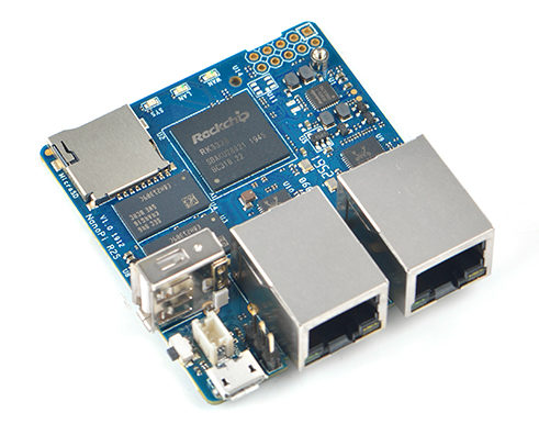
In a bid to achieve full rate dual Gigabit, the FriendlyElec’s team is currently working on its latest open-source IoT application artifact which is an upgraded version of the NanoPi R1S SBC & Gateway, called the NanoPi R2S.
In contrast to the NanoPi R1S which came with 512MB RAM, an Allwinner H3 / H5 processor and a USB 2.0 to Ethernet Controller to mention a few, the new NanoPI R2S is based on the Rockchip RK3328 processor and is expected to come with more system memory including a 1GB DDR4 RAM, along with support for the 4G LTE via Huawei 8372H-155 USB dongle and two Gigabit Ethernet ports (with one deployed for WAN and the other for LAN) each capable of attaining close to 1Gbps.
While most of the features feel like an upgrade, the NanoPi R2S will not be spotting an On-board wiFi due to unclear reasons and it certainly makes things feel like a downgrade on that end. However, instead of the On-board WiFi, friendlyELEC recommends the use of the RTL8821CU USB dongles which will be supported out-of-the-box by the default firmware.
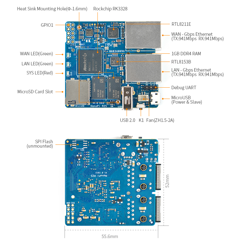
NanoPi R2S Layout
Asides dropping the WiFi and possible memory increases, most of the other features of the new board seem quite similar to the earlier one, although there is a 10-pin I / O in the R2S which cannot be found in the NanoPi R1S board.
Some of the highlight features and specifications of the new R2S include:
1 x Ethernet port using the GMAC from the chip, 1 x Ethernet port relying on a USB 3.0 to Ethernet controller
1 micro USB port (power + slave)
1 USB Type-A host port
Debug Serial Port: 3.3V TTL level and 3Pin 2.54mm pitch pin header
5V DC / 2A power supply via Micro USB por
tTemperature range of 0℃ to 80℃
Supports Ubuntu – Core, U-boot, OpenWrt as software/operating systems
completely open-source for secondary development of personal NAS and enterprise IoT
While the NanoPi R2S board is not yet available with no release date specified, it is certain the board will come at a price more expensive than the NanoPi R1S due to the increased memory and the USB 3.0 to Ethernet controller.
More about the board can be found on its wiki page.
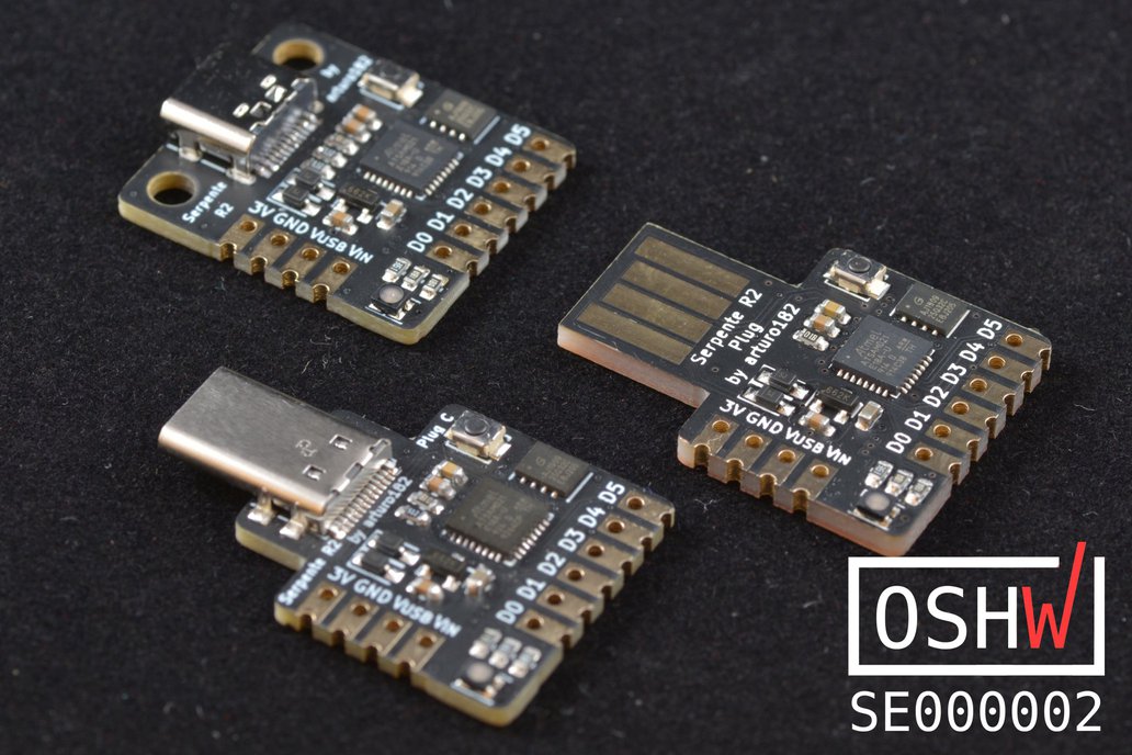
CircuitPython’s user base is growing even though a lot of people believe Micropython is a better route. It enjoys the rigorous backing 0f one of the major drivers of the Maker community (Aka Adafruit) and recently has been the “embedded Python” stack of choice for several open-source development boards. One such board is the Serpentine boards created by the popular Arturo182.
According to the board’s description on Tindie, the Serpentine boards are “a low-cost development boards designed to be used with Adafruit’s CircuitPython”. The boards are based on Microchip SAMD21 Arm Cortex-M0+ microcontroller and they bear a striking resemblance to the Digisparks boards which the description on Tindie mentioned as the inspiration for the serpentine, “both in form-factor as well as use-cases”. The Serpentine comes with a 256KB of flash, 32KB of RAM and a 4MB flash which is used for storing CircuitPython code and program files. The board operates on a 3.3V power and Logic level but it comes with a 250mA LDO regulator which ensures it can be powered off a USB port.
Highlight features of the board include:
ATSAMD21E18A 32-bit Cortex-M0+ running at 48MHz
256KB flash and 32KB RAM
4MB Flash for storing files and CircuitPython code
6 highly customizable GPIOs
250mA LDO
3.3V logic and power
Powered either from USB or external source
User-controlled RGB LED
Mounting holes on the Serpente female Type-C board
Castellated edges so the boards can be used as modules easily
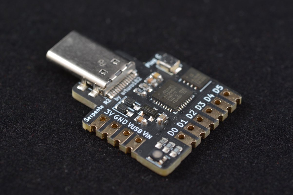
One of the major swings in board designs in 2019 was the migration from MicroUSB ports to USB TypeC ports. It became a hugely popular thing with existing boards creating board revisions with USB Type C ports, and new boards adding it to the options. Serpentine was also created with this in mind as it comes in three versions with the only difference being the USB Connectors. The three versions include the standard Serpente board which comes with a female USB Type-C connector, the Serpente Plug C which comes with a male USB Type-C connector, and the Serpente Plug which uses the board itself as a Type-A USB plug.
The Serpentine boards are available on Tindie for $15 and have so far been bought by 183 people with all 5-stars review.
More information on the board’s features, application and ordering perks can be found in its Tindie Page.
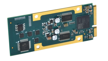
Acromag adds another military-grade measurement and control module to its AcroPack series of ruggedized mini PCIe I/O modules. The new AP730 multi-function I/O module performs analog input, analog output, discrete I/O and counter/timer functions. A variety of carrier cards can host up to four modules and are available in PCIe, VPX, XMC, CompactPCI-Serial, and mini-ITX embedded computing platforms. These boards are designed for commercial off-the-shelf (COTS) applications in defense, aerospace, and industrial systems to provide a high-density mix of I/O signal interfaces in compact computing environments. With the AP730’s single-module combination of analog and digital I/O functions, system integrators can use remaining carrier mezzanine slots for serial, Ethernet, avionics, and CAN interfaces, or FPGA signal processing with other AcroPack modules.
Each AP730 module features a high-density mix of 28 I/O channels and 32-bit counter/timers in a 30 x 70mm card. Eight differential analog inputs (0-10V, ±10V ranges) feed a 16-bit A/D converter capable of sampling at nearly 800KHz. Four analog output channels have individual 16-bit D/A converters with a 7.5µS settling time. Programmable I/O ranges, sequencing, interrupts, memory allocation, and other controls are supported, as well as external triggering. The bidirectional digital I/O is configured as two 8-channel groups with TTL-compatible thresholds and programmable change-of-state or level interrupts. Counter/timers perform quadrature, frequency, and period measurement functions plus pulse width modulation and waveform generation operations. DMA transfer support efficiently moves data between module memory and the PCIe bus to unburden the system CPU and increase performance.
“Increasing demand for more efficient size, weight, and power (SWaP) computing is driving the need for high-density, multi-function I/O modules like the AP730,” stated Robert Greenfield, Acromag’s Business Development Manager. “The compact yet rugged AcroPack mezzanine is ideal for interfacing a mix of signals in the tightest footprint on PCIe servers, VPX chassis or small form factor computers.”
AcroPack mezzanine modules improve on the mini PCI Express architecture by adding a down-facing 100-pin connector that securely routes the I/O through a carrier card without any loose internal cabling. Carrier cards for rack-mount, field-deployable, industrial chassis, desktop, and small mezzanine computing platforms let you combine up to four I/O function modules on a single computer board. More than 25 models are available for data acquisition, signal processing, test & measurement, command/control, and network communication applications. Software tools support embedded applications running on Linux®, Windows®, or VxWorks® operating systems.
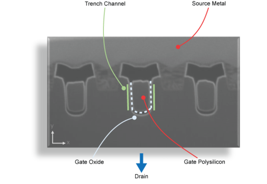
The MOSFET gate-source threshold voltage (VGS-th) and maximum gate-source voltage(VGS-max) are key parameters that are critical to the reliable operation of MOSFETs. The threshold voltage represents the voltage at which the MOSFET starts to turn on, whilst the maximum gate-source voltage is the maximum gate-source voltage that the MOSFET can withstand safely. VGS-max ratings vary between suppliers and between MOSFETs, which can make it difficult to choose appropriate MOSFETs for the application. This application note aims to provide the designer with enough knowledge to appreciate these differences and to select an appropriate MOSFET. We also present a new methodology demonstrating where higher VGS-max rating voltages may be applied for Nexperia’sautomotive grade MOSFETs.
Designing in MOSFETs for safe and reliable gate-drive operation – [PDF]
Ken Shirriff published an interesting article on his blog. He writes:
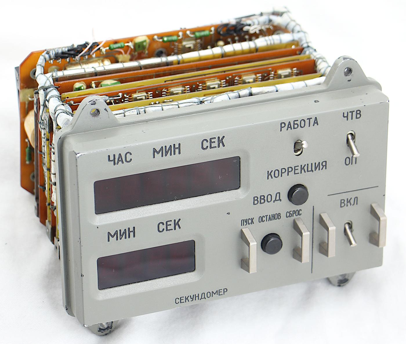
We recently obtained a clock that flew on a Soyuz space mission.1 The clock, manufactured in 1984, contains over 100 integrated circuits on ten circuit boards. Why is the clock so complicated? In this blog post, I examine the clock’s circuitry and explain why so many chips were needed. The clock also provides a glimpse into the little-known world of Soviet aerospace electronics and how it compares to American technology.
Inside the digital clock from a Soyuz spacecraft – [Link]
There are several situations where using an RTC could adversely affect your project by increasing cost, size, time accuracy or IO requirements. To prevent this, especially in ESP/WiFi-based or other clock-reliant projects, makers usually turn to obtain time information from NTP servers. I recently came across a project by BitsandBlobs which used standalone NTP Servers and I felt it might be one of the best ways to introduce to this concept. So for today’s tutorial, we will build an NTP Based Network Time Clock based on “BitsandBlobs” build.
NTP (Network Time Protocol) is an internet protocol used for synchronizing clocks on computer networks within a few milliseconds of universal coordinated time (UTC). Using this protocol, devices can request and receive UTC data from an NTP server which usually receives precise time from an atomic clock.
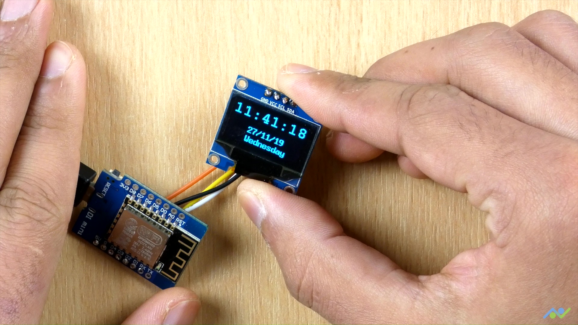
The WiFi capabilities of the ESP8266 based Wemos D1 mini will be used in obtaining time information from a public NTP server and it will be displayed in a user-friendly manner on an OLED display.
At the end of this project, you would know not only how to obtain time information from NTP servers, but also how to use the WemosD1 for your WiFi projects.
Network Clock using ESP8266 and OLED display – [Link]
There are several situations where using an RTC could adversely affect your project by increasing cost, size, time accuracy or IO requirements. To prevent this, especially in ESP/WiFi-based or other clock-reliant projects, makers usually turn to obtain time information from NTP servers. I recently came across a project by BitsandBlobs which used standalone NTP Servers and I felt it might be one of the best ways to introduce to this concept. So for today’s tutorial, we will build an NTP Based Network Time Clock based on “BitsandBlobs” build.
NTP (Network Time Protocol) is an internet protocol used for synchronizing clocks on computer networks within a few milliseconds of universal coordinated time (UTC). Using this protocol, devices can request and receive UTC data from an NTP server which usually receives precise time from an atomic clock.
The WiFi capabilities of the ESP8266 based Wemos D1 mini will be used in obtaining time information from a public NTP server and it will be displayed in a user-friendly manner on an OLED display.
At the end of this project, you would know not only how to obtain time information from NTP servers, but also how to use the WemosD1 for your WiFi projects.
Required Components
The following components are required to build this project:
The components can be purchased from the attached links. While an interesting enclosure was built for this project, for those who don’t have access to a 3D printer and don’t want to solder the components, you can go for the option of implementing the project on a breadboard.
Schematics
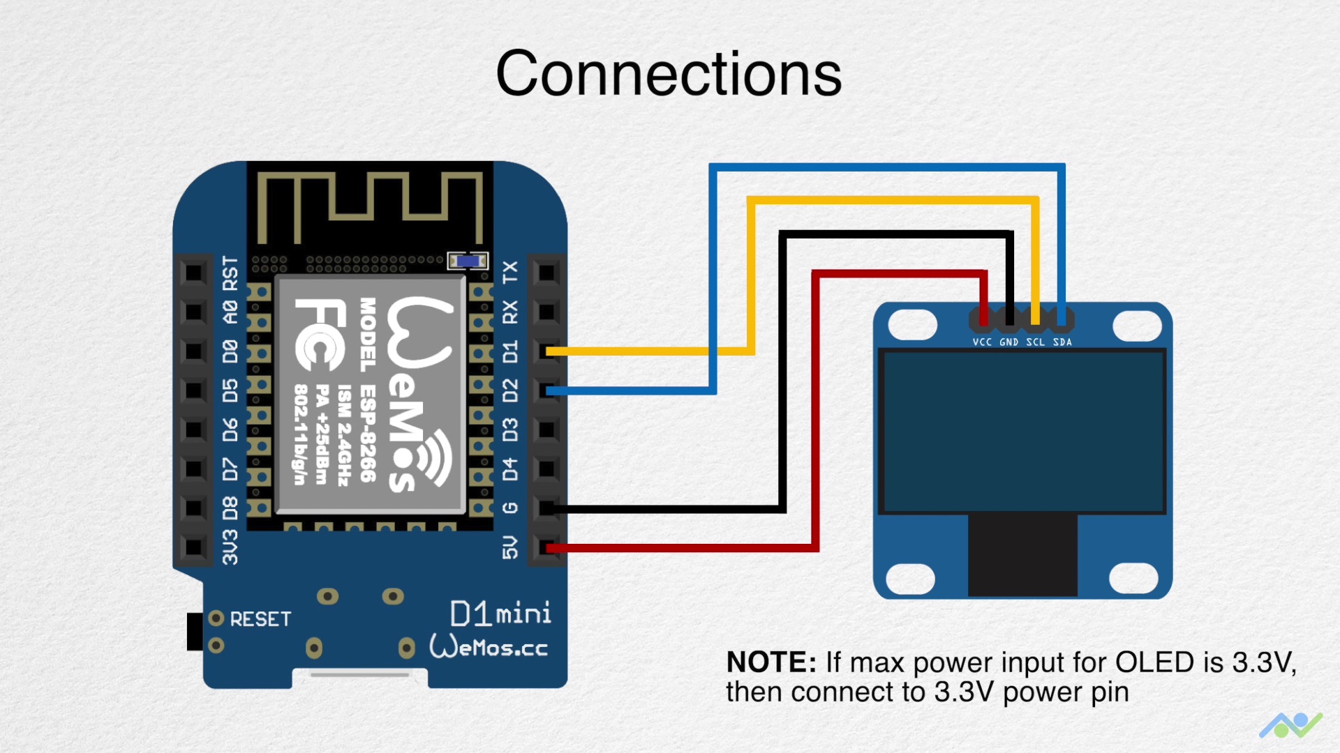
Thanks to the use of just two components, the schematics for today’s project is super straightforward. The OLED display being used communicates with the host microcontroller via I2C as such all we need do is connect the display to the I2C pins of the Wemos D1 mini as shown in the schematics below:
Schematics (Credits: BitsandBlobs)
To make the connections easier to follow, a pin-pin map is provided below:
Wemos D1 – OLED
D1 - SCL
D2 - SDA
5v - VCC
GND - GND
It is important to note the maximum input voltage of your OLED display and be sure it is 5V tolerant. You should connect the VCC pin of the OLED to the Wemos D1’s 3.3v pin if 5V is too high for the display.
With the schematics complete, we can now proceed to the code for the project.
Code
The Arduino IDE is used for the code developing of this project, as such, if this is the first time are using an ESP8266 based board with the IDE, you will need to install the ESP8266 support for it. Follow this tutorial we wrote a while back on “Programming an ESP8266 Board with the Arduino IDE” to get it done.
The algorithm behind the code for today’s project is quite straightforward. We start by connecting the Wemos D1 to the internet via a WiFi Access point and access an NTP server to obtain the network time. We convert network time to our local time equivalent and display the local time on the OLED display.
To make writing the code easier, we will use some libraries including; the ESP8266WIFI library, the Time library, and the U8g2 library. The ESP8266WIFI library is used for everything related to connecting the Wemos to the internet through a WiFi access point, while the Time Library has function implementations that enable us easily extract time from NTP servers, and the U8g2 library allows us to interact with the OLED and display text on it in fancy fonts. The ESP8266WiFi and Time library comes pre-installed with the ESP8266 Arduino IDE support while the U8g2 library will need to be installed via the Arduino Library Manager or by downloading from the link attached above.
With the libraries installed, we are now ready to go over the code. As usual, I will do a quick run through it and try to explain some of the concepts in it that might be difficult to follow.
We start as usual by including all the libraries that we will use.
Next, we provide the credentials (SSID and Password) of the WiFi access point through which the Wemos will access the internet and also specify the address of the NTP server we will connect to along with the timezone string which is used to correct the clock from the NTP server and to match that of our timezone. Since time zones are different, and the clock will not be correct if you don’t augment it with the time zone string, you might need to visit Remote Monitoring System’s website to get the correct time zone string (TZ_INFO) for your particular location.
const char* ssid = "Access point's SSID";
const char* password = "Access point's PASSWORD";
const char* NTP_SERVER = "ch.pool.ntp.org";
const char* TZ_INFO = "GMT+0BST-1,M3.5.0/01:00:00,M10.5.0/02:00:00"; // enter your time zone (https://remotemonitoringsystems.ca/time-zone-abbreviations.php)
Next, we declare a few important variables that will be used to store data during the program run and create an instance of the U8g2 library with the pins of the Wemos D1 to which the OLED is connected, as arguments.
tm timeinfo;
time_t now;
long unsigned lastNTPtime;
unsigned long lastEntryTime;
U8X8_SSD1306_128X64_NONAME_SW_I2C u8x8(/* clock=*/ SCL, /* data=*/ SDA, /* reset=*/ U8X8_PIN_NONE); // OLEDs without Reset of the Display
Next is the void setup() function. We start the function by initializing the OLED display and Serial communication with a baud rate of115200.
void setup()
{
u8x8.begin();
Serial.begin(115200);
Serial.println("\n\nNTP Time Test\n");
Next, we connect the Wemos to the WiFI access point using the WiFi.begin() function with the credentials of the access point as arguments. The program is stalled in a perpetual loop till the Wemos has connected successfully to the access point.
WiFi.begin(ssid, password);
Serial.print("Connecting to network");
int counter = 0;
while (WiFi.status() != WL_CONNECTED)
{
delay(200);
if (++counter > 100)
ESP.restart();
Serial.print( "." );
}
Serial.println("\nWiFi connected\n\n");
Next, we use the configtime() function to initialize a connection with the NTP server and use the setenv() function to set the time zone. Timezone codes for different regions can be also be obtained from Nayarsystems github page.
configTime(0, 0, NTP_SERVER);
// See https://github.com/nayarsystems/posix_tz_db/blob/master/zones.csv for Timezone codes for your region
setenv("TZ", TZ_INFO, 1);
With that done, we then make attempts to sync the NodeMCU with the NTP server using the getNTPtime() function. If the sync is not successful, the ESP is restarted, but if successful, the current time from the NTP server is saved as the NTP time and millis() is kickstarted so the time can be tracked and updated locally.
if (getNTPtime(10))
{
// wait up to 10sec to sync
}
else
{
Serial.println("Time not set");
ESP.restart();
}
showTime(&timeinfo);
lastNTPtime = time(&now);
lastEntryTime = millis();
}
Next, we move to the void loop() function.
The loop() function is quite straight forward. We simply get the time from the time using the getNTPtime() function and display it on the OLED with the showTime(&timeinfo) function. A delay of 1000ms is added to the code to ensure the text is displayed smoothly.
The two key functions driving behind the code for the project are the getNTPtime() and the showTime() functions.
The getNTPtime uses the millis() function to keep track of the last time received from the NTP server and update the current time based on it. The time and date information are obtained from the data received from the NTP server and the “timeinfo” variable is updated with that data.
bool getNTPtime(int sec)
{
{
uint32_t start = millis();
do
{
time(&now);
localtime_r(&now, &timeinfo);
delay(10);
} while (((millis() - start) <= (1000 * sec)) && (timeinfo.tm_year < (2016 - 1900)));
if (timeinfo.tm_year <= (2016 - 1900))
return false; // the NTP call was not successful
Serial.print("Time Now: ");
Serial.println(now);
}
return true;
}
The showtime() function, on the other hand, splits up the timeinfo variable and displays the time information including the date, day of the week, and clock, on the OLED display, as well as the serial monitor.
The last function in the sketch is the getDOW() function which is used to convert the numeric day of the week value from the time struct, into a String(the name value).
char * getDOW(uint8_t tm_wday)
{
switch(tm_wday)
{
case 1:
return "Monday";
break;
case 2:
return "Tuesday";
break;
case 3:
return "Wednesday";
break;
case 4:
return "Thursday";
break;
case 5:
return "Friday";
break;
case 6:
return "Saturday";
break;
case 7:
return "Sunday";
break;
default:
return "Error";
break;
}
}
The complete code for the project is provided below and also attached in the zip file under the download section.
#include <ESP8266WiFi.h>
#include <time.h>
#include <U8x8lib.h>
const char* ssid = "Access point's SSID";
const char* password = "Access point's PASSWORD";

const char* NTP_SERVER = "ch.pool.ntp.org";
const char* TZ_INFO    = "GMT+0BST-1,M3.5.0/01:00:00,M10.5.0/02:00:00";  // enter your time zone (https://remotemonitoringsystems.ca/time-zone-abbreviations.php)
tm timeinfo;
time_t now;
long unsigned lastNTPtime;
unsigned long lastEntryTime;

U8X8_SSD1306_128X64_NONAME_SW_I2C u8x8(/* clock=*/ SCL, /* data=*/ SDA, /* reset=*/ U8X8_PIN_NONE);   // OLEDs without Reset of the Display
void setup()
{
  u8x8.begin();

  Serial.begin(115200);
  Serial.println("\n\nNTP Time Test\n");
WiFi.begin(ssid, password);

  Serial.print("Connecting to network");
  int counter = 0;
  while (WiFi.status() != WL_CONNECTED)
  {
    delay(200);
    if (++counter > 100)
      ESP.restart();
    Serial.print( "." );
  }
  Serial.println("\nWiFi connected\n\n");
configTime(0, 0, NTP_SERVER);
 // See https://github.com/nayarsystems/posix_tz_db/blob/master/zones.csv for Timezone codes for your region
 setenv("TZ", TZ_INFO, 1);
if (getNTPtime(10))
  {
    // wait up to 10sec to sync
  }
  else
  {
    Serial.println("Time not set");
    ESP.restart();
  }
  showTime(&timeinfo);
  lastNTPtime = time(&now);
  lastEntryTime = millis();
}
void loop()
{
  getNTPtime(10);
  showTime(&timeinfo);
  delay(1000);
}
bool getNTPtime(int sec)
{
  {
    uint32_t start = millis();
    do
    {
      time(&now);
      localtime_r(&now, &timeinfo);
      delay(10);
    } while (((millis() - start) <= (1000 * sec)) && (timeinfo.tm_year < (2016 - 1900)));

    if (timeinfo.tm_year <= (2016 - 1900))
        return false;  // the NTP call was not successful

    Serial.print("Time Now: ");
    Serial.println(now);
  }
  return true;
}
void showTime(tm *localTime)
{
  //print to serial terminal
  Serial.print(localTime->tm_mday);
  Serial.print('/');
  Serial.print(localTime->tm_mon + 1);
  Serial.print('/');
  Serial.print(localTime->tm_year - 100);
  Serial.print('-');
  Serial.print(localTime->tm_hour);
  Serial.print(':');
  Serial.print(localTime->tm_min);
  Serial.print(':');
  Serial.print(localTime->tm_sec);
  Serial.print(" Day of Week ");
  Serial.println(localTime->tm_wday);
  Serial.println();

  //display on OLED
  char time_output[30];

  u8x8.setFont(u8x8_font_courB18_2x3_f);
  u8x8.setCursor(0,0);
  sprintf(time_output, "%02d:%02d:%02d", localTime->tm_hour, localTime->tm_min, localTime->tm_sec);
  u8x8.print(time_output);

  u8x8.setFont(u8x8_font_8x13B_1x2_f);
  u8x8.setCursor(4,4);
  sprintf(time_output, "%02d/%02d/%02d", localTime->tm_mday, localTime->tm_mon + 1, localTime->tm_year - 100);
  u8x8.print(time_output);

  u8x8.setCursor(4,6);
  u8x8.print(getDOW(localTime->tm_wday));
}
char * getDOW(uint8_t tm_wday)
{
  switch(tm_wday)
  {
    case 1:
      return "Monday";
      break;

    case 2:
      return "Tuesday";
      break;

    case 3:
      return "Wednesday";
      break;

    case 4:
      return "Thursday";
      break;

    case 5:
      return "Friday";
      break;

    case 6:
      return "Saturday";
      break;

    case 7:
      return "Sunday";
      break;

    default:
      return "Error";
      break;
  }
}
Demo
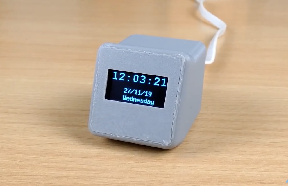
Go over the connections again and ensure you have the ESP8266’s Arduino IDE board support package installed along with the U8g2 library. Once confirmed, connect the Wemos D1 to your computer and select it in the Arduino IDE along with the port to which it is connected. Hit the upload button and wait for the completion of the upload process. When Completed, you should see the time and date information is displayed on the OLED as shown in the image below.
The clock is working (Credits: BitsandBlobs)
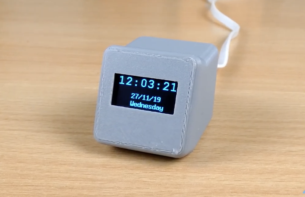
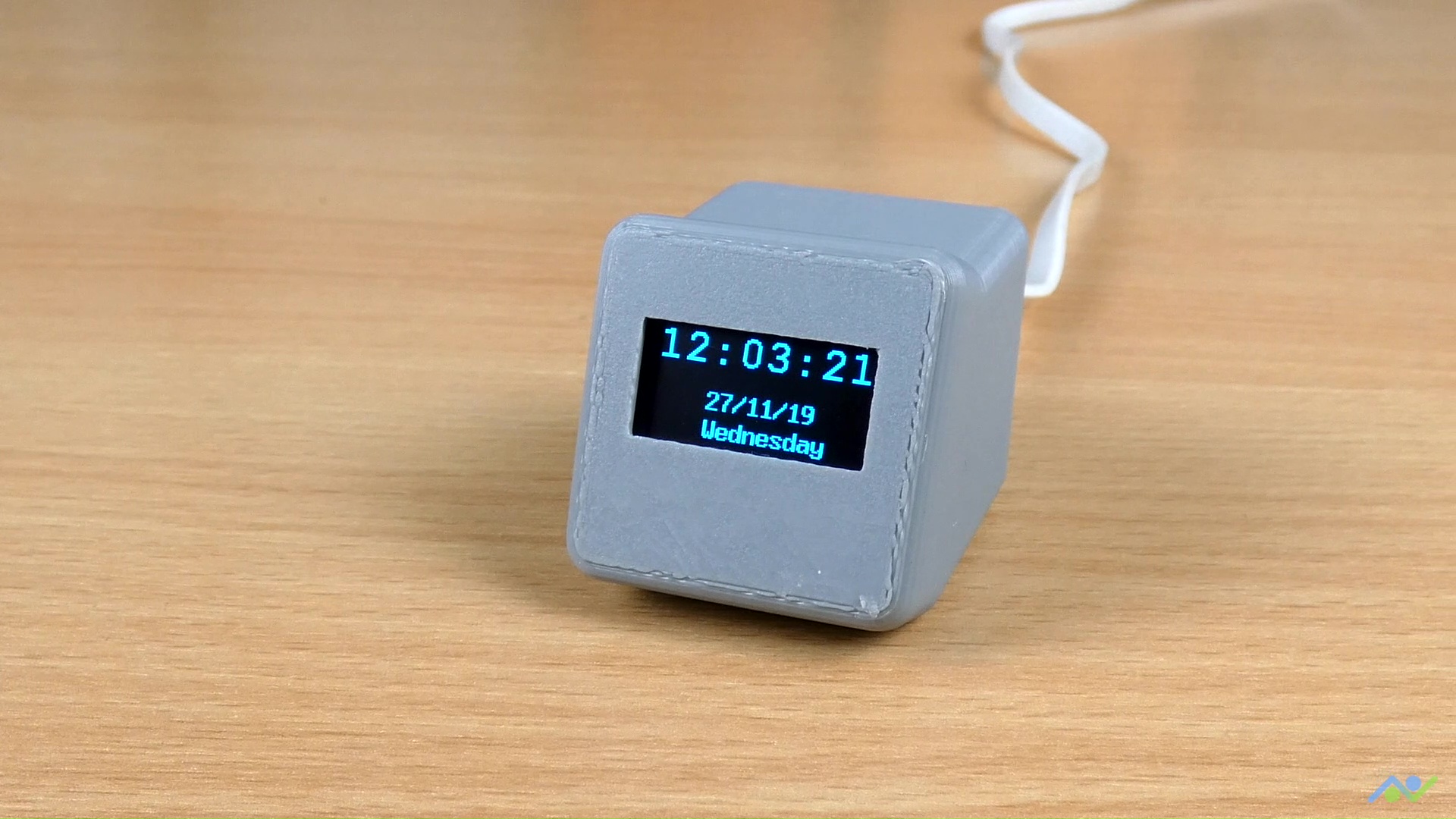
Going Further
To take things further, one of the quick things you can do is hook up the device into the 3D printed enclosure designed by “BitsandBlobs”. The design and assembly instructions are available on Thingiverse, so all you need to do is to download and print it. After putting it in the 3D printed enclosure, the clock looks like the image below.
Demo with Enclosure (Credit: BitsandBlobs)
That’s it for this tutorial, thanks for reading. Do let me know via the comment section if you built one of these and also let me know if you have any challenges replicating them.
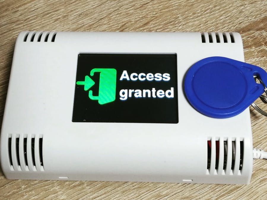
RFID based projects are one of the most popular Arduino projects out there and we have also built a couple of them here too, but I recently came across an RFID access control project by hwhardsoft that was built using the ArduiTouch MKR enclosures. The ready-made nature of the enclosures and their existence for different kinds of boards caught my attention and I felt it might be of interest to most readers here too. So for today’s project, we will build an RFID based Access Control system using the ArduiTouch MKR enclosure, an Arduino MKR WiFi 1010 and an InnovateKing-EU RFID reader.
The ArduiTouch series of enclosures come with a display already fitted on a PCB specifically designed for a specific family of maker board. The best way to describe them will be “evaluation boards with screens and enclosures for maker boards”. The ArduiTouch MKR enclosure to be used today, was designed for the Arduino MKR family of boards and it comes with; an 120 x 80 x 33 mm enclosure for top wall mounting, a 2.4-inch resistive touch TFT, an integrated voltage regulator, an integrated piezo beeper, breadboard area for easy mounting of components, and a slot for an MKR shield.
All of the above features make it easy to create a very nice looking RFID reader, with TFT output for wall/door mounting with an Arduino MKR of your choice. The Arduino MKR of choice selected for this tutorial is the Arduino MKR WiFi 1010, and the RFID module selected is the InnovateKing-EU RFID Reader.
At the end of today’s tutorial, you would know not only how to build a fancy RFID reader but also the intricacies of working with an ArduiTouch MKR Enclosure and using the InnovateKing-EU RFID Reader.
Arduino RFID Reader using the ArduiTouch MKR Enclosure – [Link]
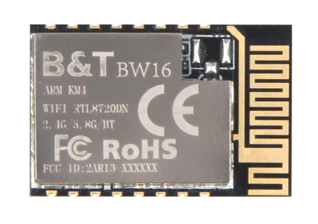
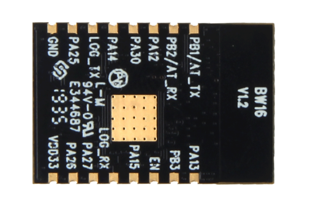
Realtek8720DN is a WiFi and Bluetooth module that has dual bands for WiFi communication. It is worth saying that this little module can support WiFi 5G and Bluetooth Low Energy 5.0 as well. This WiFi and Bluetooth module is a highly integrated WiFi and Bluetooth module with the main chip RTL8720DM, it can be regarded as an SoC for the WiFi and Bluetooth application with typical SBCs.
Except for the main chip, the Realtek8720DN module consists of a high-performance MCU named KM4, a low power MCU named KM0, WLAN (802.11 a/b/g/n) MAC, a 1T1R capable WLAN baseband, RF, Bluetooth, and peripherals. An inner antenna and many interfaces are available in this little WiFi and Bluetooth module.
Key Features
WiFi and Bluetooth module.
Support both WiFi 2.4G and WiFi 5G with protocol 802.11 a/b/g/n 1×1 from 20/40 MHz up to MCS7.
Support WiFi low power mode.
Support Bluetooth (BLE) 5.0.
Peripheral Interfaces
1 common ADC interface
2 log UART with standard baud rate support
1 I2C interfaces are shared with the PWM interfaces
1 SPI interfaces are shared with the PWM interfaces
4 PWM interfaces
All of the above interfaces can be used as GPIO
Compare with ESP series, this WiFi and Bluetooth module has more functions like 5G WiFi and Bluetooth 5.0. As a matter of fact, this little module can be widely used for more applications than the ESP series.