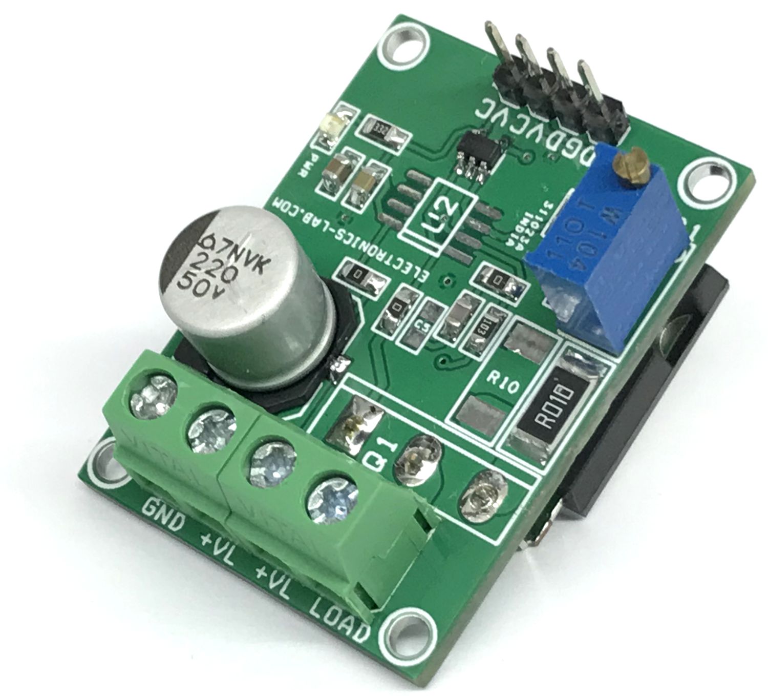
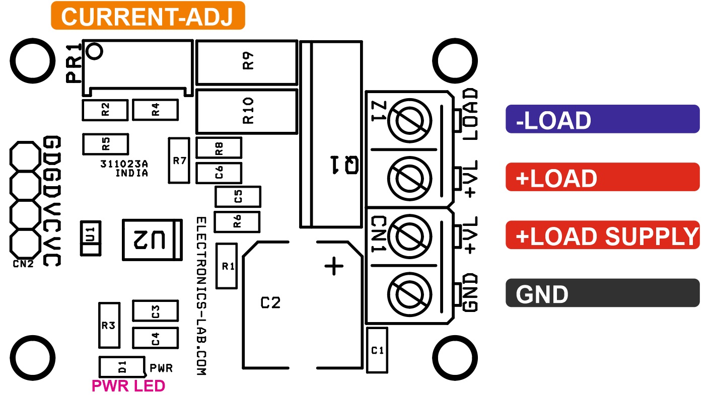
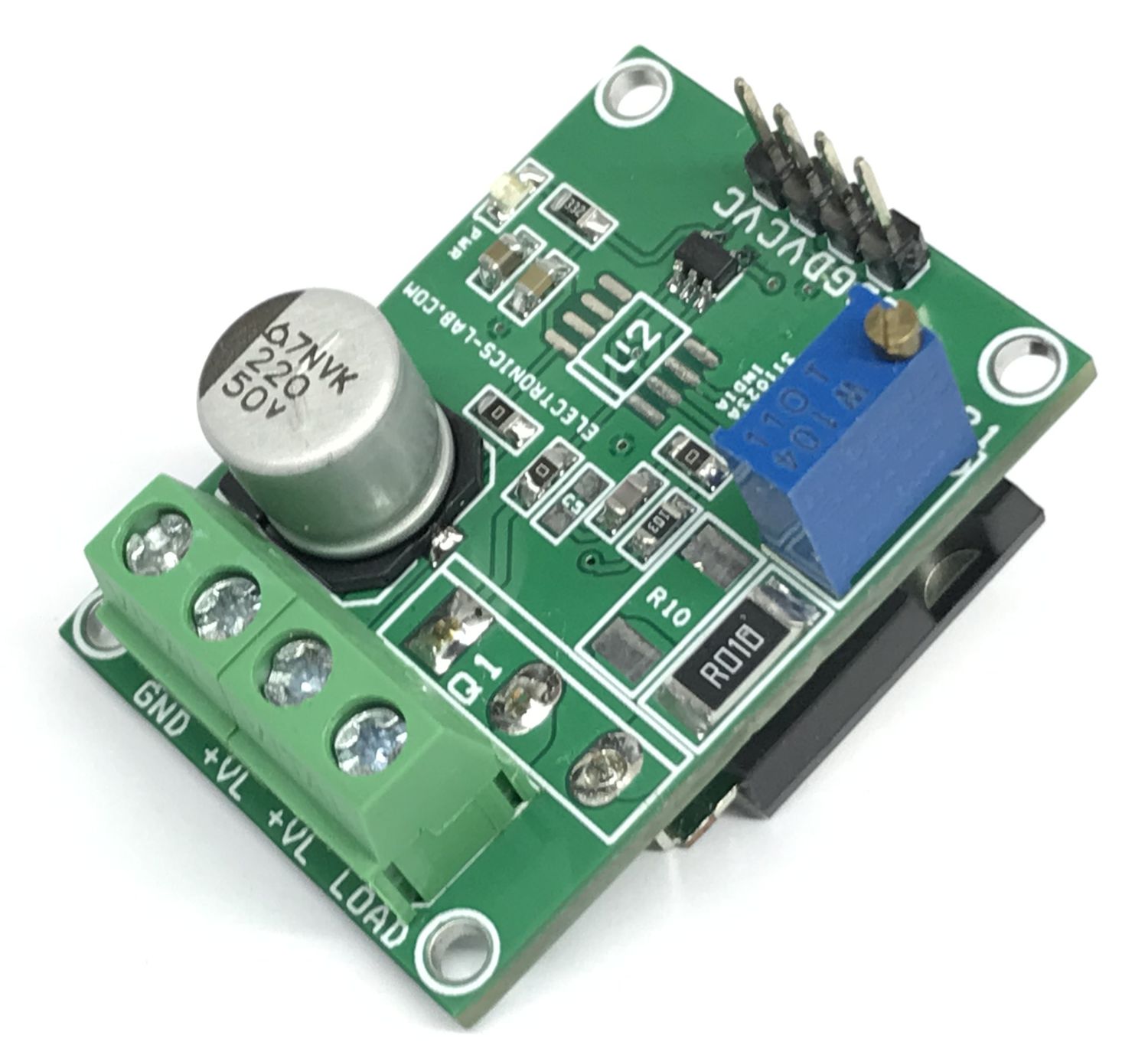
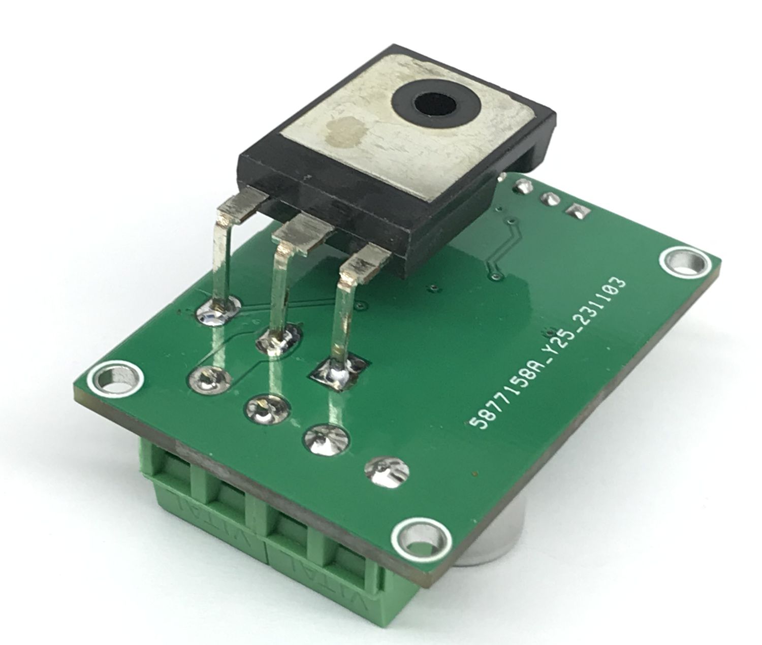
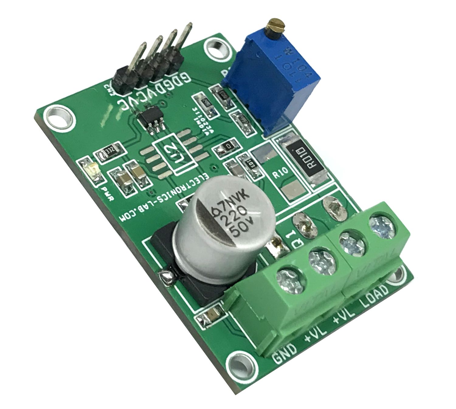
This voltage-to-current (V-I) converter delivers a well-regulated current to a load. The circuit accepts an adjustable input voltage from Trimmer potentiometer PR1 and converts it to an output current from 0A to 1A. The current is regulated by feeding the voltage across a low-side, current-sense resistor R9 back to the OPAMP. The output Darlington pair allows for higher current gain. Feedback components R8 and C6 provide frequency compensation to ensure the stability of the circuit during transients. They also help reduce noise. R8 provides a DC feedback path directly at the current setting resistor, R9, and C1 provide a high-frequency feedback path that bypasses the NPN pair.
Note: The project can support higher current and voltage ranges by changing the sense resistor, BJT transistor, and Input voltage. It is important to use an appropriate heatsink for Q1 to take care of overheating.
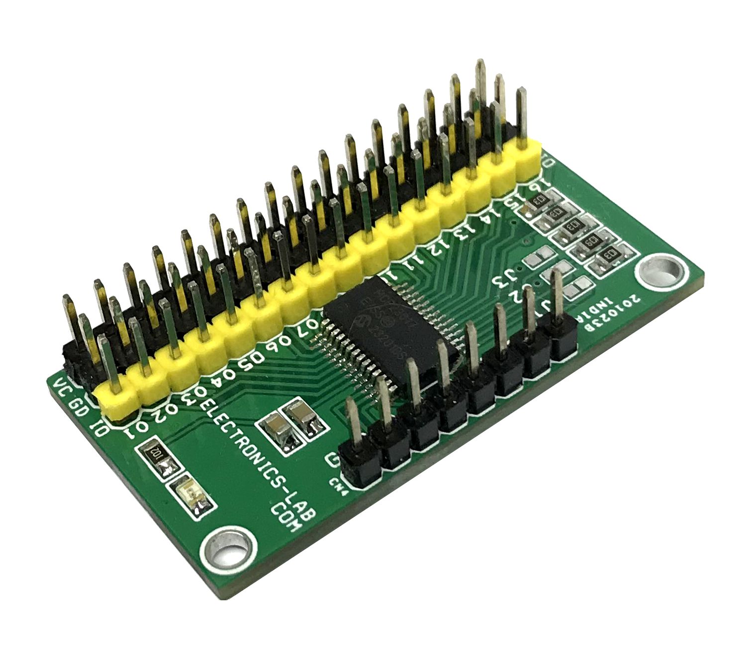
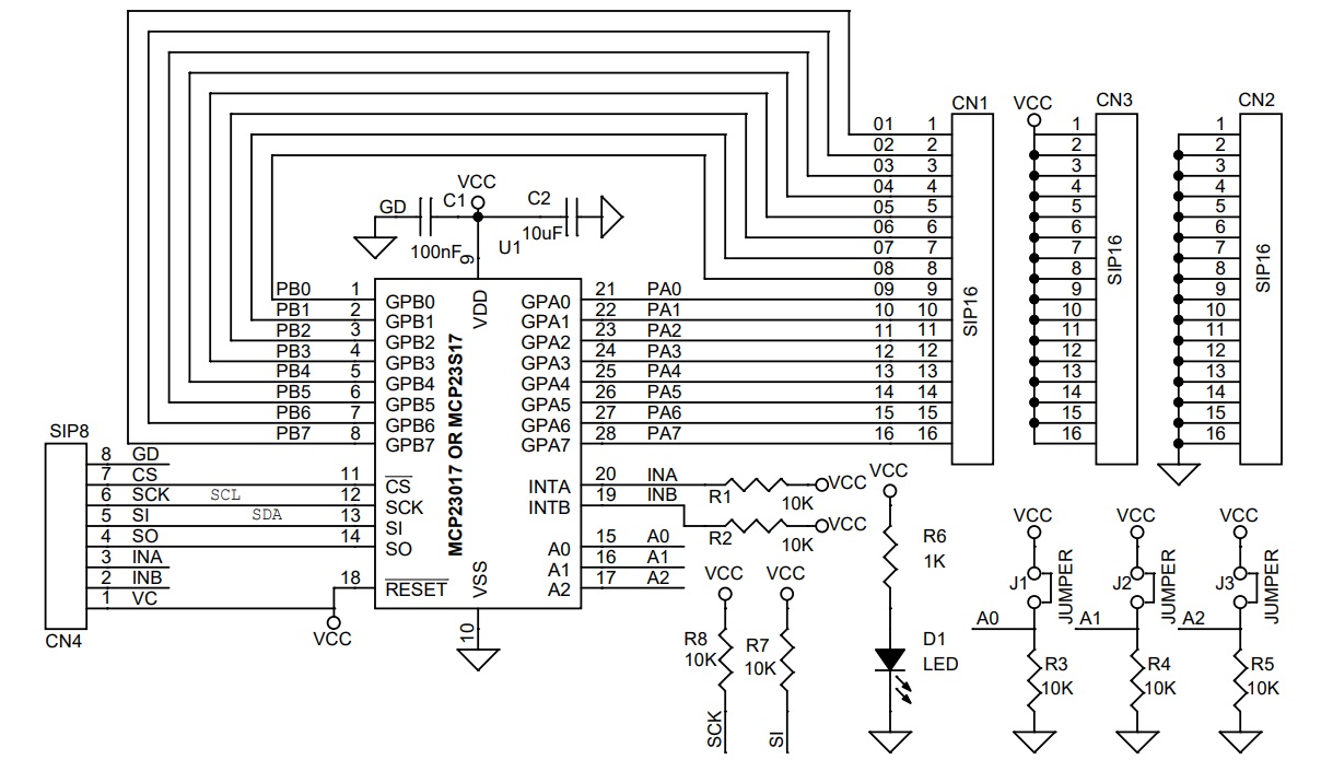
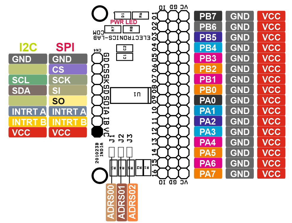
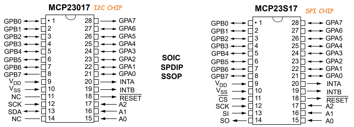
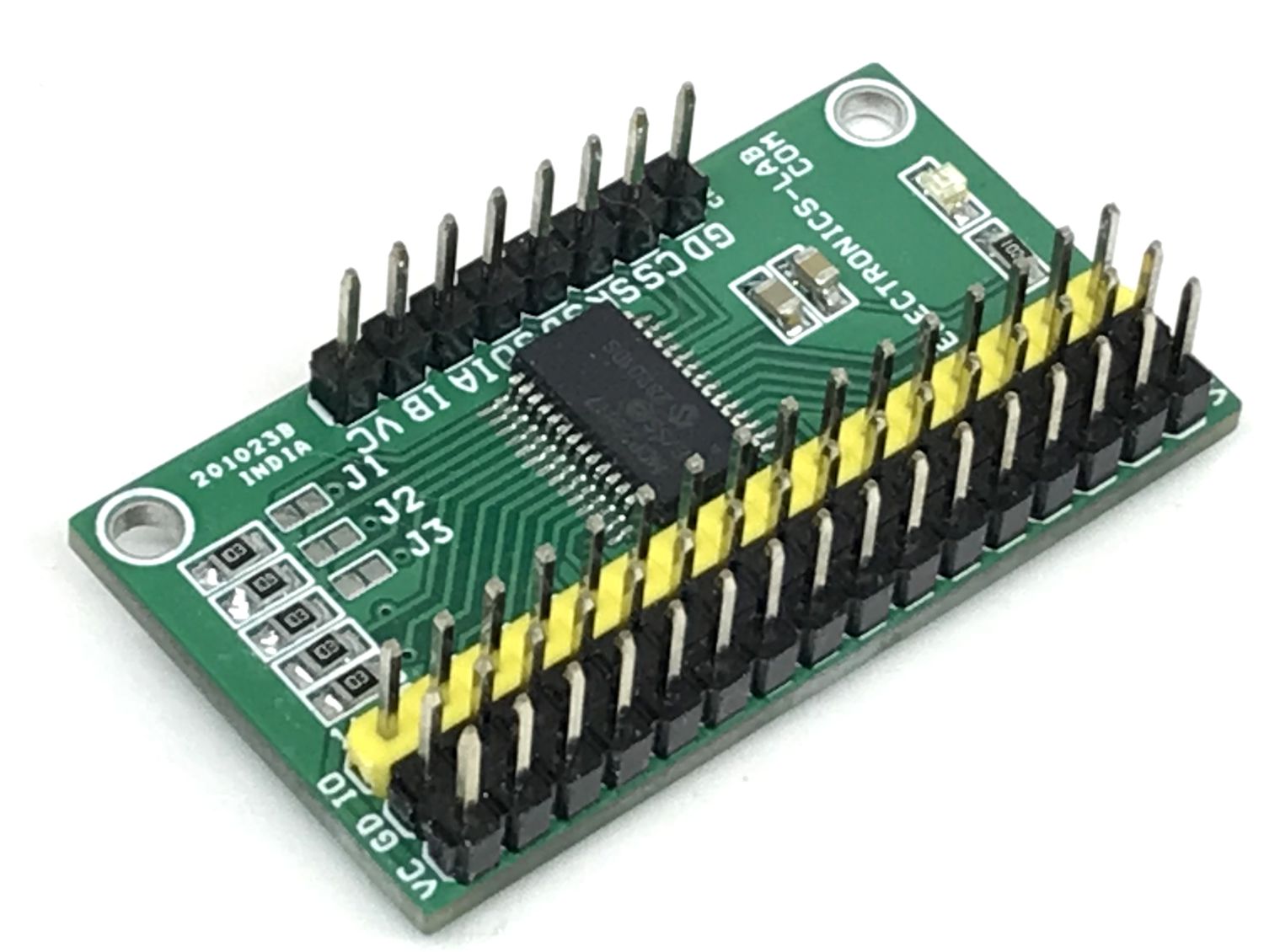
This project provides 16-bit, general-purpose parallel I/O expansion for I2C or SPI bus applications. The MCP23017 chip supports the I2C interface and the MCP23S17 chip is used for the SPI interface. The board can be populated with either SPI or I2C chip. Follow the connection diagrams for interface details.
Note: Use MCP23017 chip for I2C Interface and MCP23S17 for SPI interface. Refer to the connection diagram for I/O. Don’t install R7 and R8 if the SPI chip is used.
Three Hardware Address Pins to Allow Up to Eight Devices on the Bus
Configurable Interrupt Output Pins: Configurable as active-high, active-low or open-drain
INTA and INTB Can Be Configured to Operate Independently or Together
Configurable Interrupt Source: Interrupt-on-change from configured register defaults or pin changes
Header Connector for I2C/SPI Interface
Header Connector provided for 16 I/0 Lines, VCC and GND for easy interface
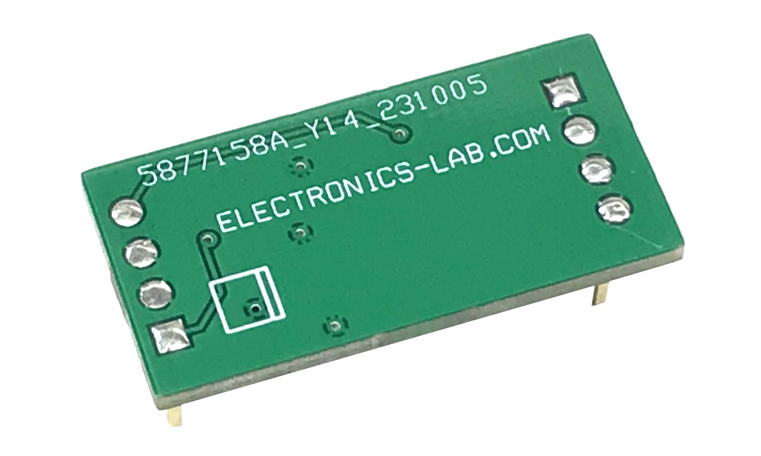
PCB Dimensions 43.97 x 24.29 mm
5mm Mounting Holes
I2C VS SPI Pins
NC/CS: Input NC (MCP23017)/Chip Select (MCP23S17)
SCK: Input Serial clock input
SDA/SI: Input/Output Serial data I/O (MCP23017)/Serial data input (MCP23S17)
NC/SO Output: NC (MCP23017)/Serial data out (MCP23S17)
INTB: Output Interrupt output for PORTB. Can be configured as active-high, active-low or open-drain.
INTA: Output Interrupt output for PORTA. Can be configured as active-high, active-low or open-drain.
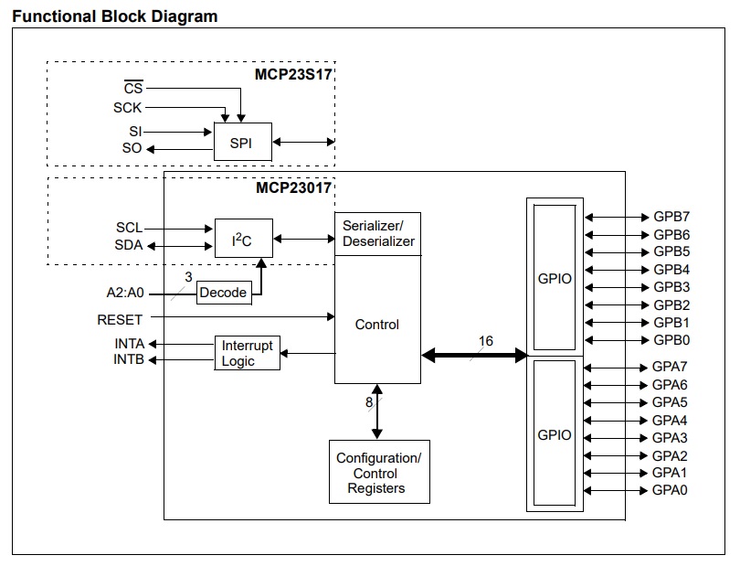
MCP23X17 consists of multiple 8-bit configuration registers for input, output and polarity selection. The system host can enable the I/Os as either inputs or outputs by writing the I/O configuration bits (IODIRA/B). The data for each input or output is kept in the corresponding input or output register. The polarity of the Input Port register can be inverted with the Polarity Inversion register. All registers can be read by the system host. The 16-bit I/O port functionally consists of two 8-bit ports (PORTA and PORTB). MCP23X17 can be configured to operate in the 8-bit or 16-bit modes via IOCON.BANK. There are two interrupt pins, INTA and INTB, that can be associated with their respective ports, or can be logically OR ’ed together so that both pins will activate if either port causes an interrupt. The interrupt output can be configured to activate under two conditions (mutually exclusive):
When any input state differs from its corresponding Input Port register state. This is used to indicate to the system host that an input state has changed.
When an input state differs from a preconfigured register value (DEFVAL register).
The Interrupt Capture register captures port values at the time of the interrupt, thereby saving the condition that caused the interrupt. The Power-on Reset (POR) sets the registers to their default values and initializes the device state machine. The hardware address pins are used to determine the device address.
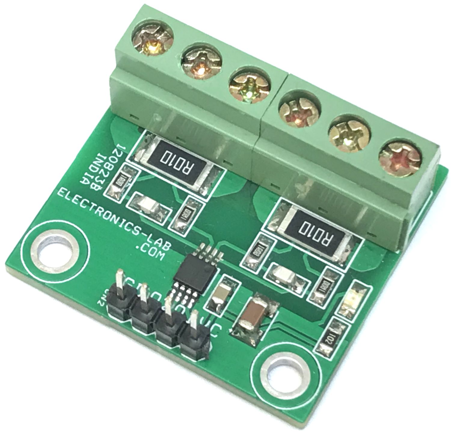
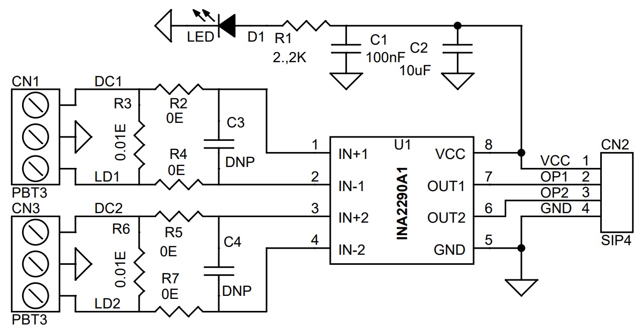
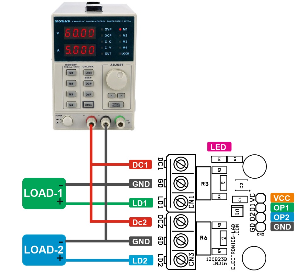
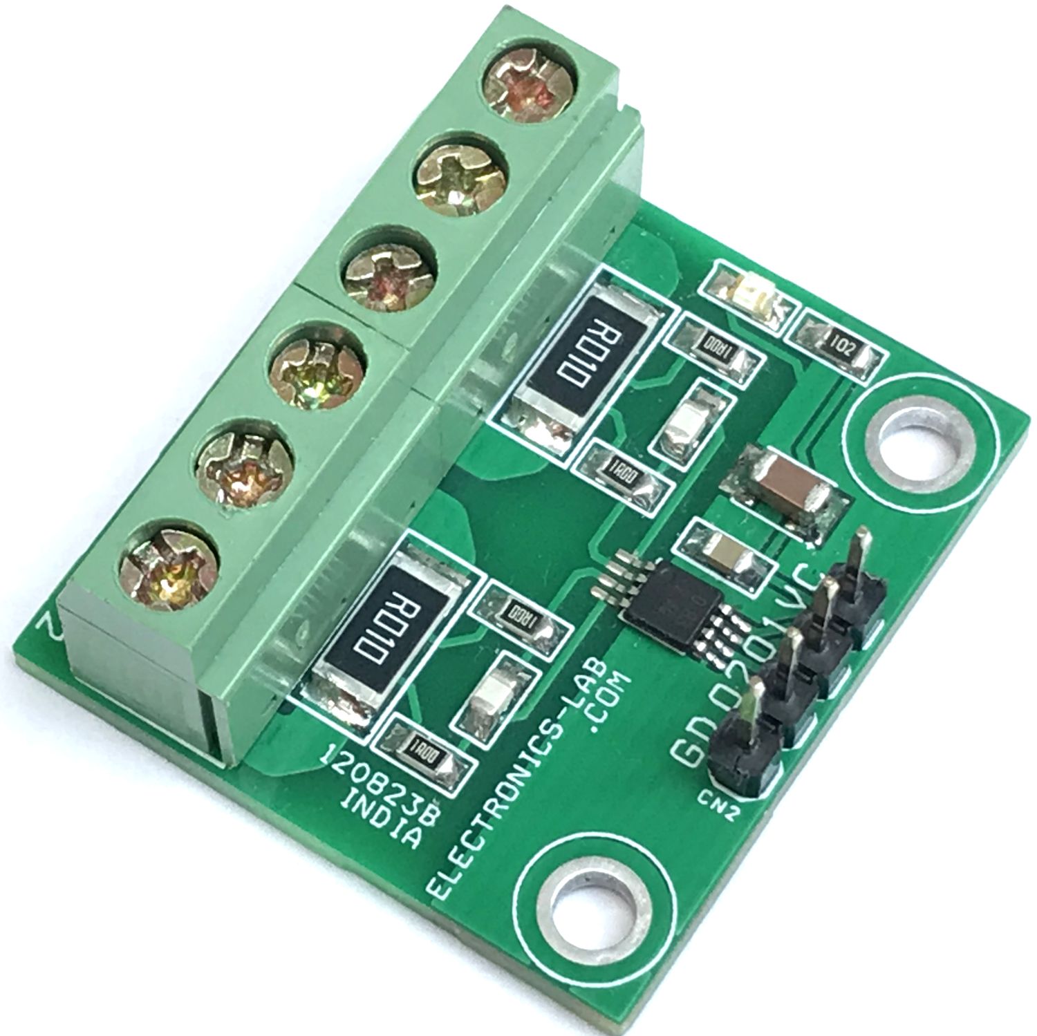
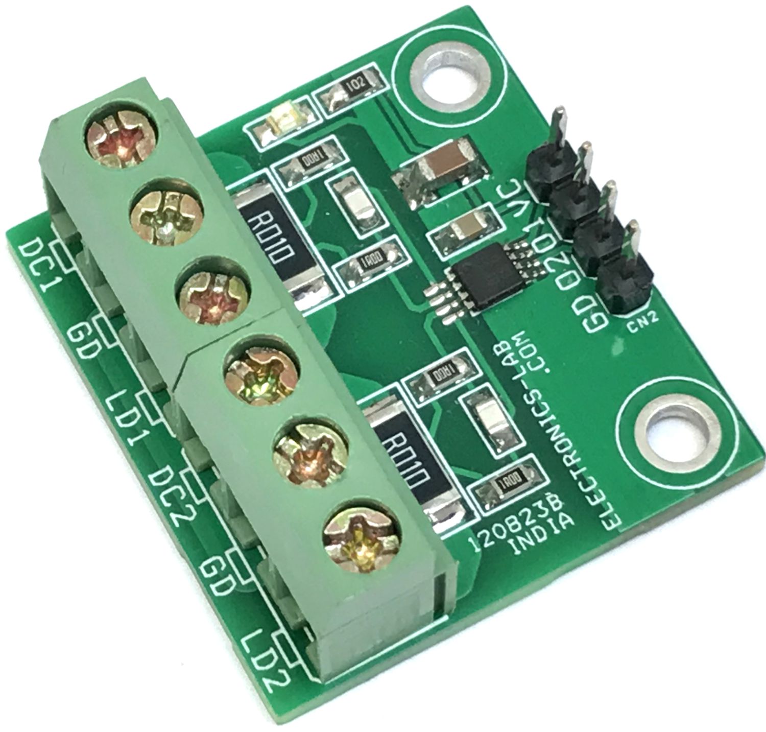
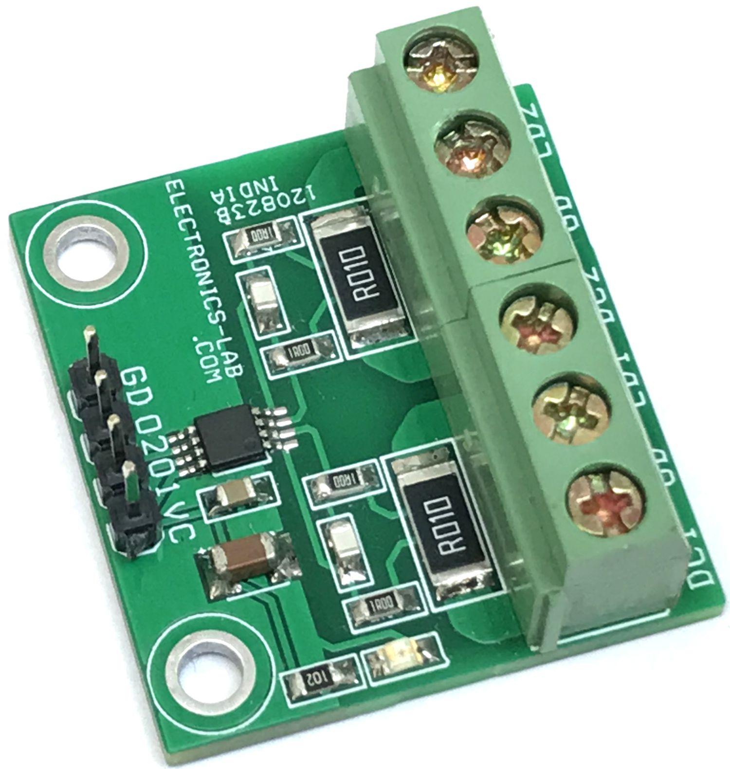
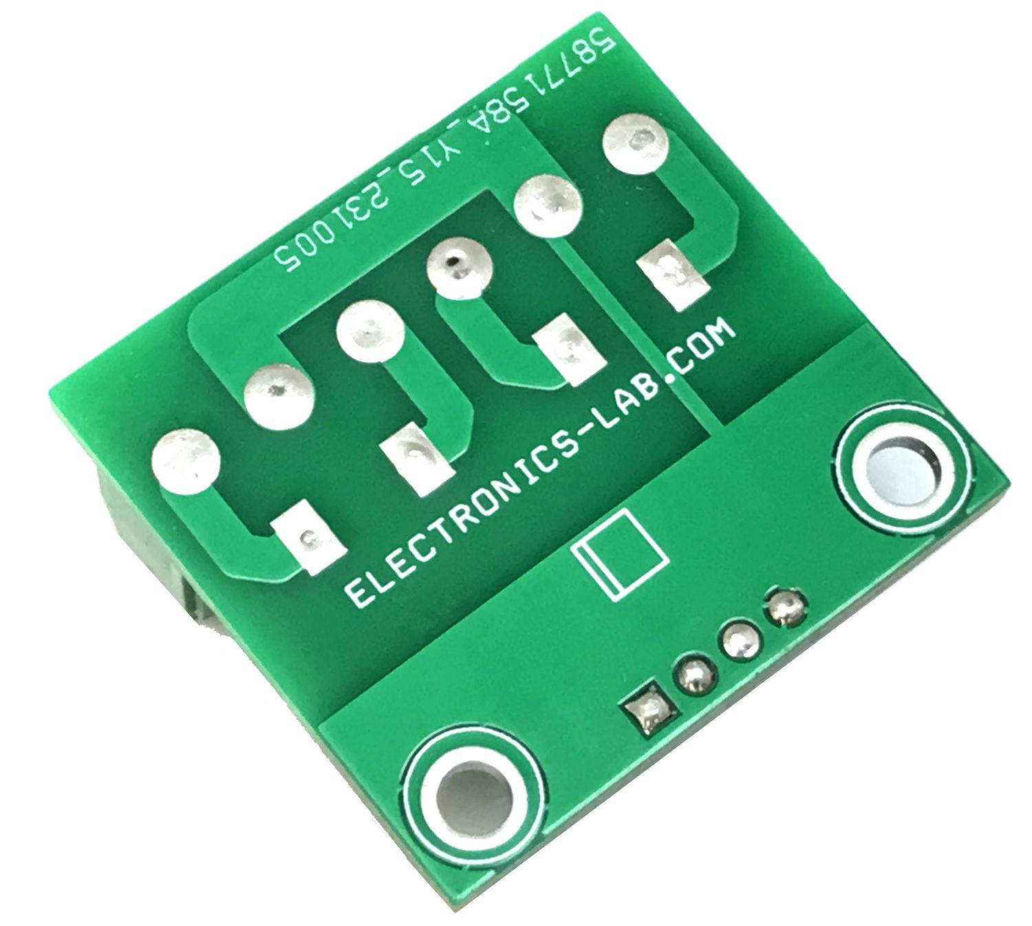
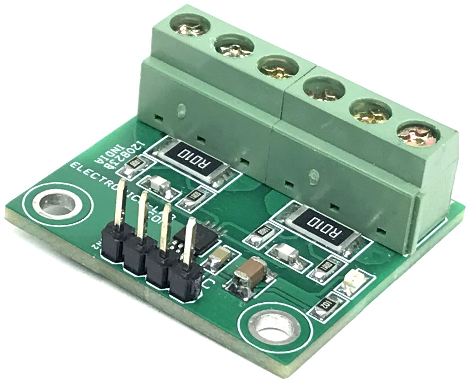
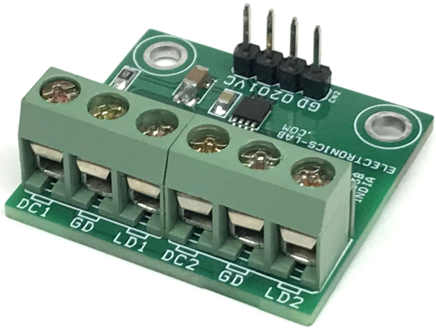
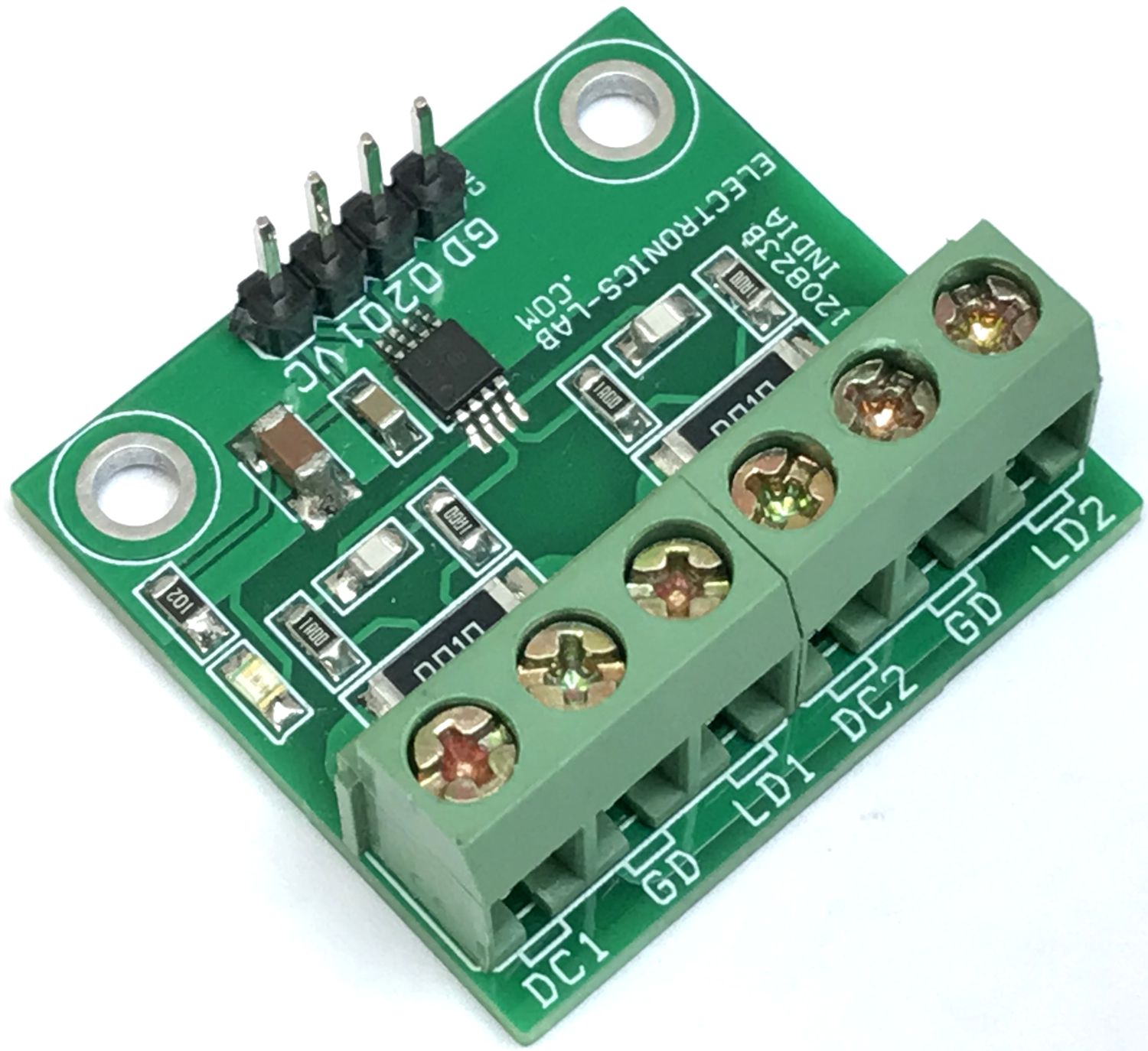
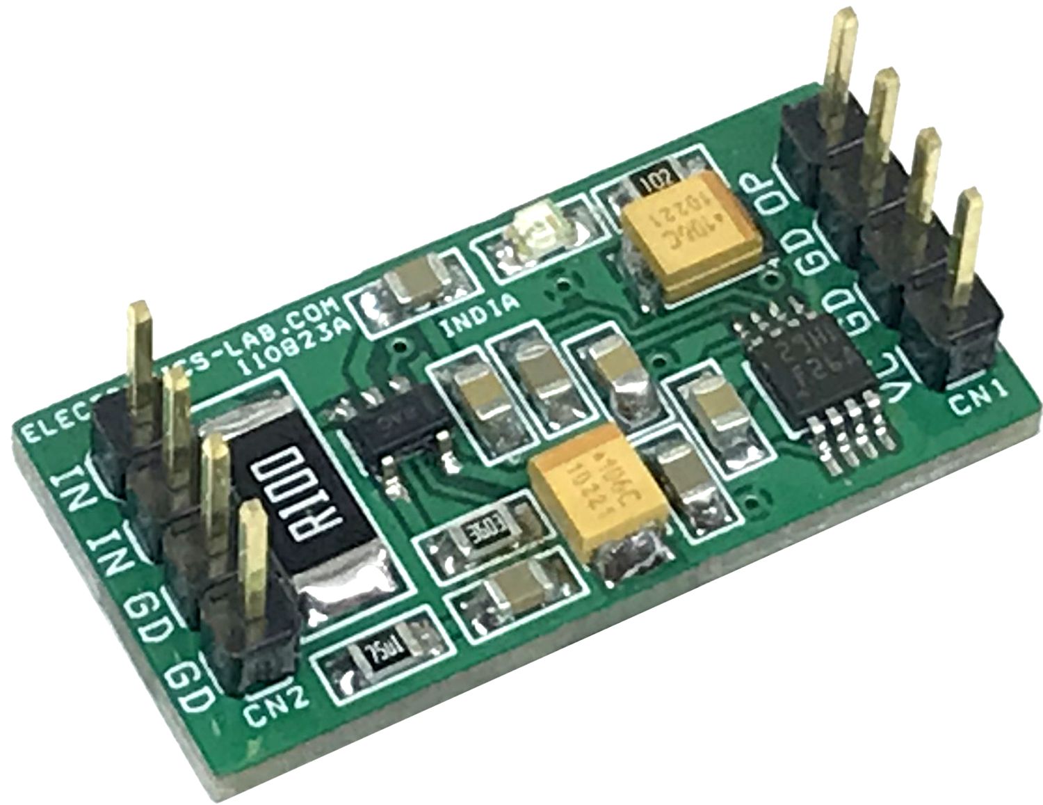
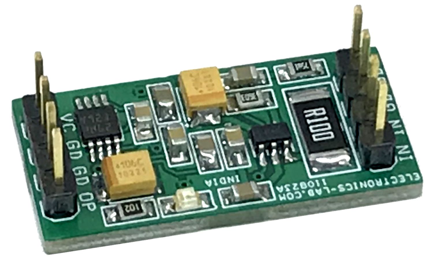
The project described here is a two-channel ultra-precise, current-sense amplifier that can measure voltage drops across shunt resistors over a wide common-mode range from 2.7 V to 120 V. The INA2290A1 chip is the heart of the project. The ultra-precise current measurement accuracy is achieved thanks to the combination of an ultra-low offset voltage of ±12 µV (maximum), a small gain error of ±0.1% (maximum), and a high DC CMRR of 160 dB (typical). The circuit is not only designed for DC measurement but also for high-speed applications (such as fast overcurrent protection, for example) with a high bandwidth of 1.1 MHz (at a gain of 20 V/V) and an 85dB AC CMRR (at 50 kHz). The project achieves ultra-precise current measurement by sensing the voltage drop across resistors R3 and R6.
The circuit operates from a single 2.7V to 20V supply with the single channel device only drawing 370µA + LED supply current per channel (typical). The devices are available with five gain options: 20 V/V, 50 V/V, 100 V/V, 200 V/V, and 500 V/V. The low offset of the zero-drift architecture enables current sensing with low ohmic shunts as specified over the extended operating temperature range (−40°C to +125°C). Screw terminals are provided to connect the load, header connector is provided to power the circuit, and analog voltage output.
Gain: the board is populated with an OPA2290A1 chip that has a gain of 20V/V, the user may choose the following chips with higher gain. Project provides 0.2V/A , 2V @ 10Amp Load.
Input Filter: Input filtering components R2, R4, R5, R7, C3, and C4 are optional. Please refer to the datasheet of the chip for guidelines on input filter components. All resistors are SMD size 0805, capacitor ceramic SMD size 0805.
INA2290A1 devices: 20 V/V
INA2290A2 devices: 50 V/V
INA2290A3 devices: 100 V/V
INA2290A4 devices: 200 V/V
INA2290A5 devices: 500 V/V
Features
Power Supply 2.7V to 20V DC
Output 0.2V/A (2V @ 10Amps)
Wide common-mode voltage: Operational voltage: 2.7 V to 120 V
Survival voltage: −20 V to +122 V
Excellent CMRR: 160-dB DC. 85-dB AC at 50 kHz
Gain 20V/V
Accuracy: Gain error: ±0.1% (maximum), Gain drift: ±5 ppm/°C (maximum),
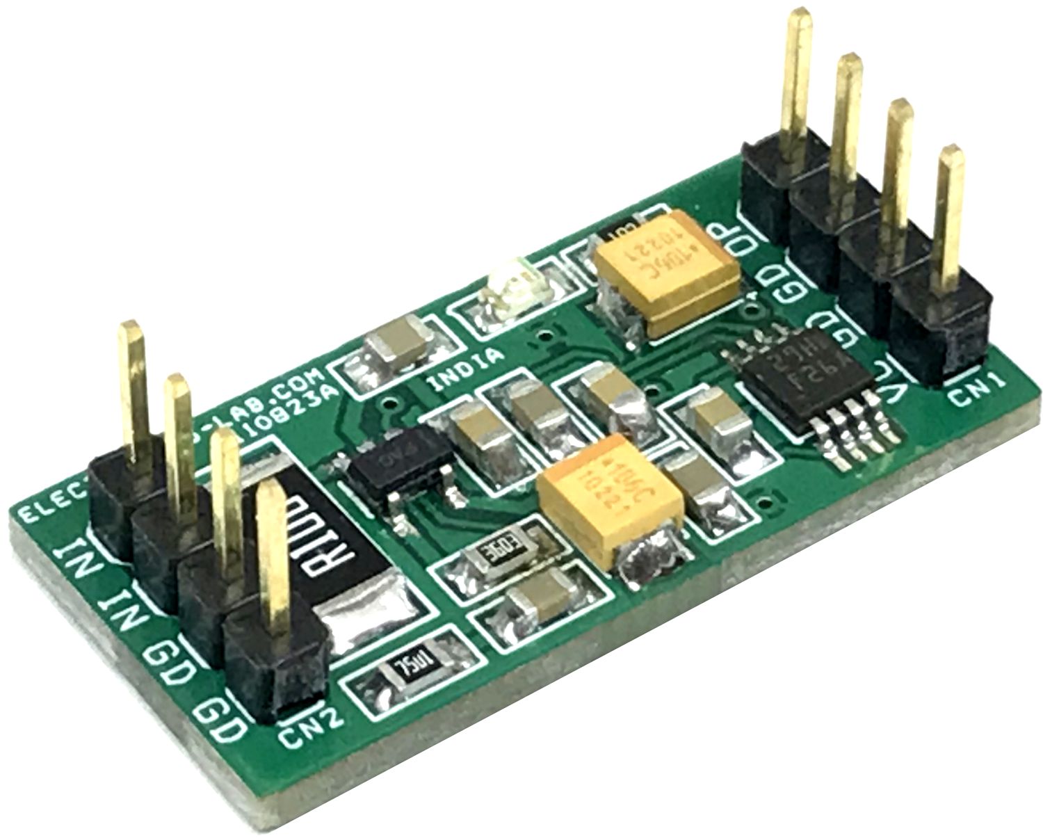
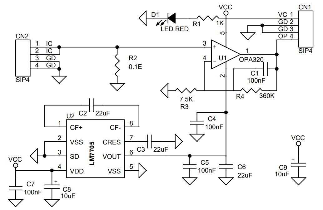
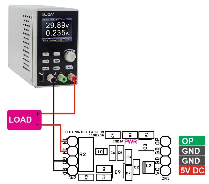
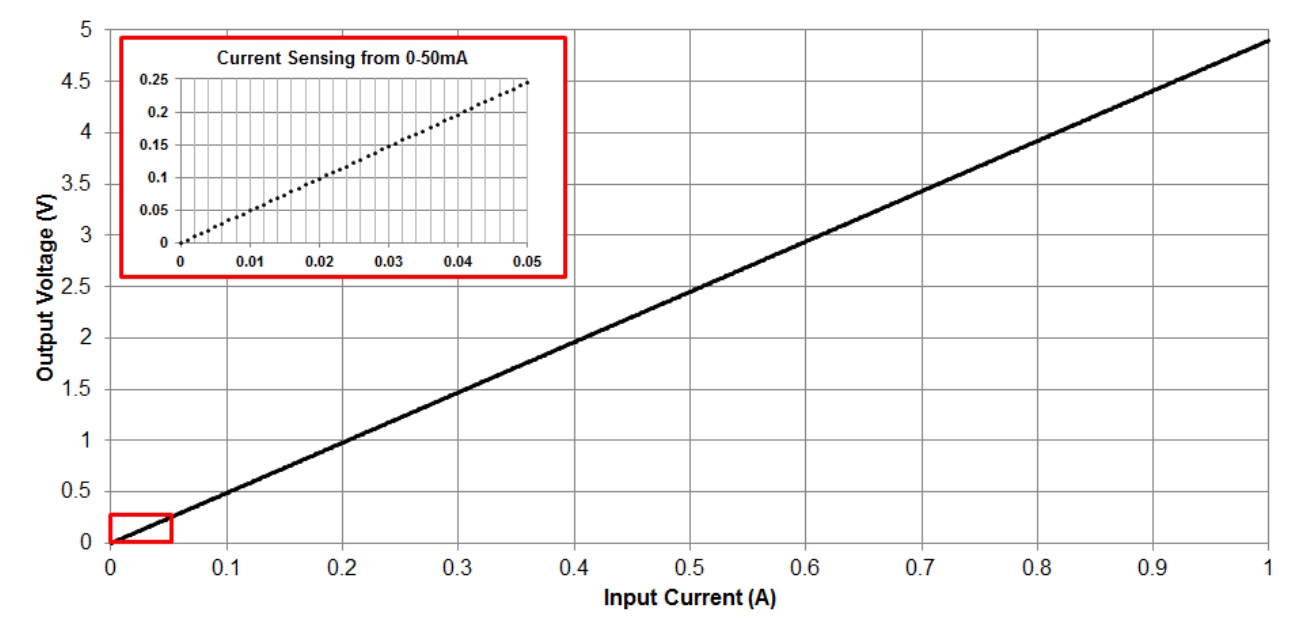
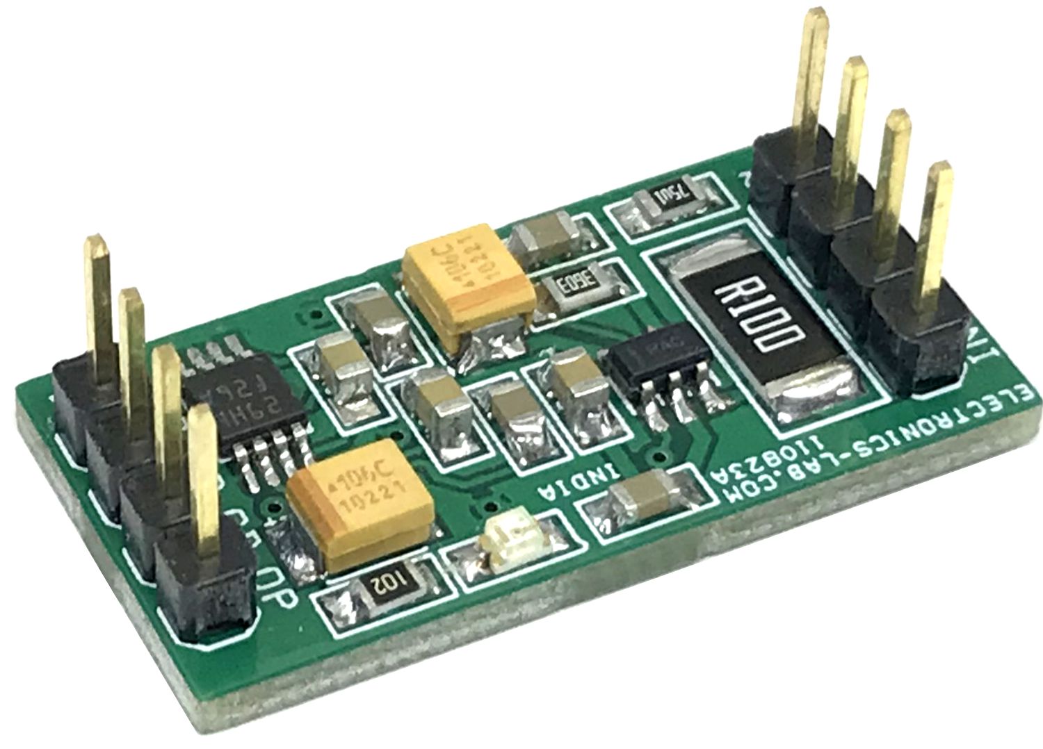
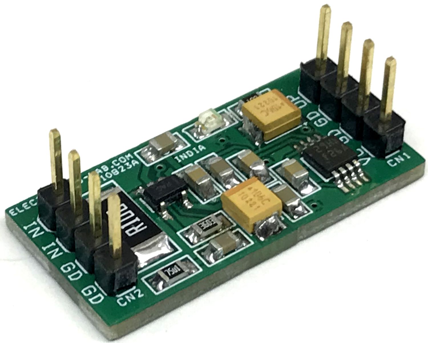
This single-supply, low-side, current sensing solution accurately detects load current between 0 and1A. The current sensor measures 0 to 1A across the shunt resistor, providing 0 to 4.9V output. The OPA320 features wide bandwidth and low offset voltage making it an excellent amplifier for this design. With a single 5V supply, the LM7705 negative bias generator extends the linear output range of the amplifier below 0V. This enables the op-amp to produce a linear output for a zero-input current condition. The wide sensing range of the design allows for precise measurement of small load currents (i.e., low-power or shutdown modes) and higher currents up to 1A. The LM7705 functions as an inverting charge pump and regulates its output to -0.23V when powered by a single supply. By biasing the negative supply (VS-) of the op-amp to -0.23V, the linear output range of the device is extended below 0V. A linear output at 0V allows a calibrated measurement of zero-input current.
For anyone with a knack for DIY projects, precision maintenance, or professional inspections, a thermal camera has become an invaluable addition to their tool collection. Looking back just a few years, they were very expensive and could only be found in military equipment. Lately, they’ve become a lot cheaper, and the InfiRay Xinfrared T2S Plus Thermal Camera is a great example of this change – combining advanced features with affordability.
Android or iOS APP
This Thermal camera is tiny, and it needs to be connected to your phone to function along with the Android or iOS app. When paired with the companion app, it lets you take thermal images or videos of any object day or night. Additionally, you can accurately measure the temperature of multiple points and take the camera outside in the dark to see everything very clearly, just like a night vision camera.
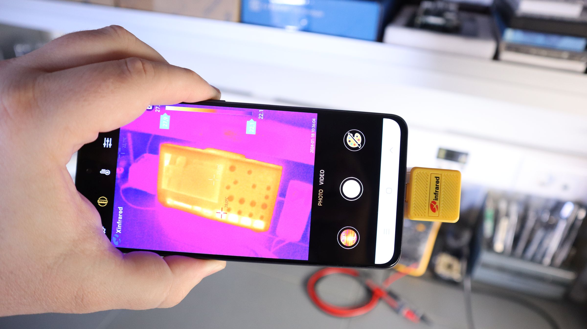
Designed to Inspect PCBs
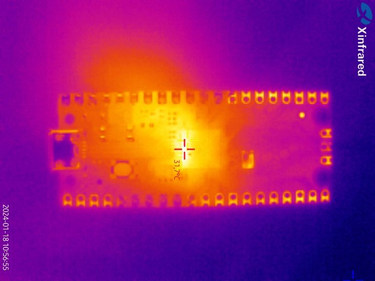
One of the main applications of these cameras is to inspect a heating component in a PCB or to find problems in wiring. It can also help you fix insulation in your home. They’re great for spotting anything that gives off heat or has a temperature difference.
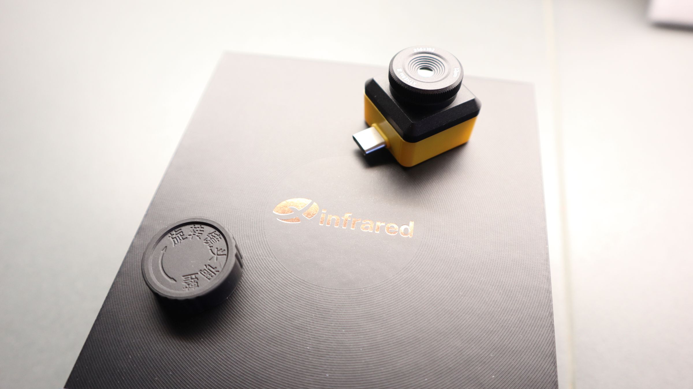
Design and Features
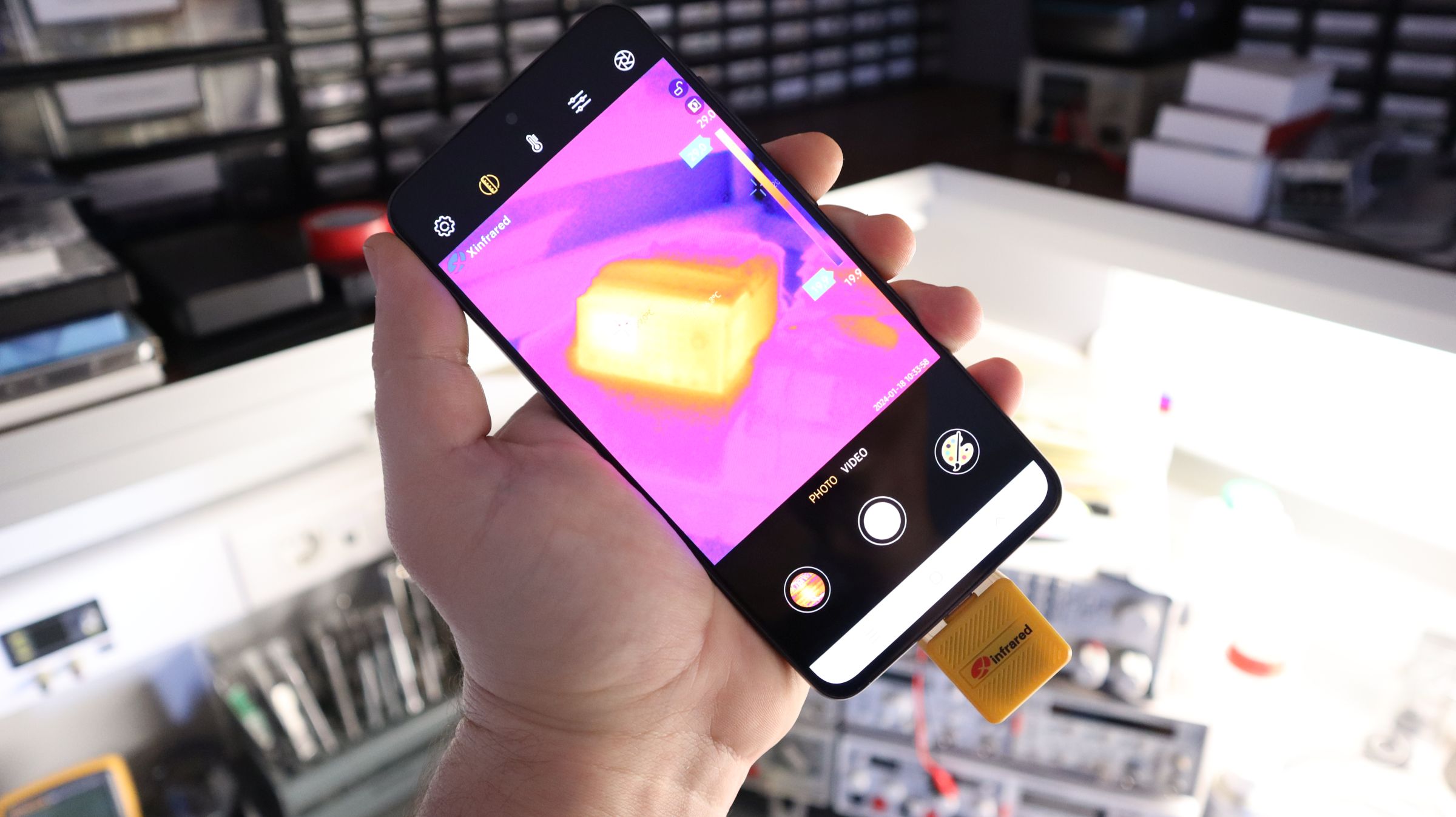
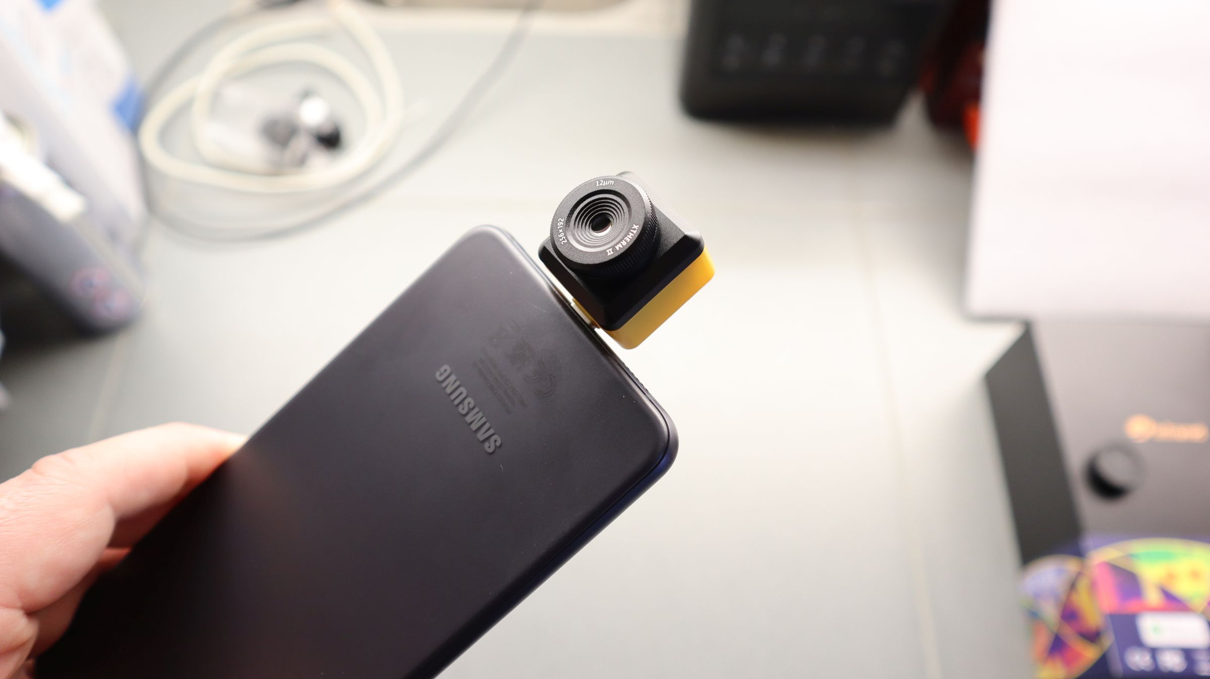
The InfiRay Xinfrared T2S Plus is a tiny thermal camera with a dimension of 26 x 26 x 24.2mm. It comes in two different variants: the One with USB-C is made for Android, and the one with the Lightning port is for IOS. To use it, you need to download the Xtherm Infrared app from the Play Store or App Store. Once the app is downloaded, you need to plug in the camera to your phone, and the app will open automatically. The camera has only one focusing lens, and all other controls are done via the Xtherm Infrared App. In the application, you can take both photos and videos, and it can also detect the temperature of a surface very accurately.
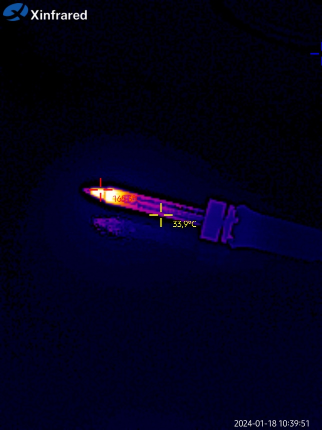
The InfiRay Xinfrared T2S Plus thermal camera lets you measure temperatures in three ways: at a specific spot, along a line, or over an area. To do this, you draw on the screen where you want to measure. The app then tells you the highest, lowest, and average temperatures for that spot, line, or area. Moreover, there’s a cool “picture in picture” mode that combines what your regular camera sees with the thermal imagery on the phone’s display. This is useful if the thermal view is hard to understand. To enable this feature, the app uses the primary camera of your phone and merges the image from the thermal camera, so the zoom level might not match up perfectly. You can also change how the thermal image looks with different pallet mode Schems, like one that makes hot things look white, giving it an X-ray-like appearance and the default is the Iron rainbow. This camera features a 25Hz refresh rate, which is faster than many other thermal cameras, thus giving you very smooth and clear images and videos.
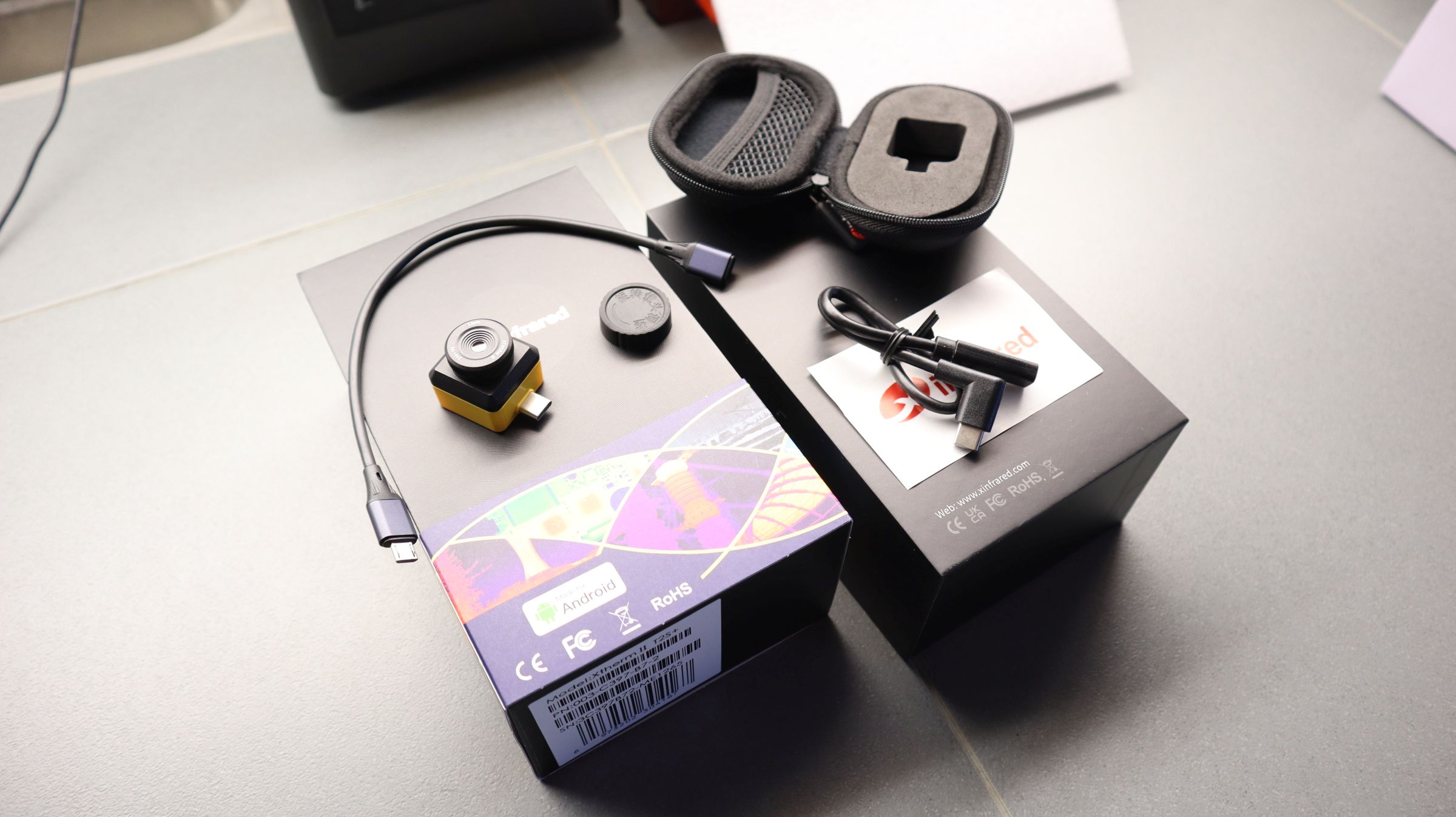
What’s in the box?
InfiRay Xinfrared T2S+ thermal camera
A Reggued Protective Case
T2S Plus Manual
USB Extension Cable
Two Stickers
Additional Accessories
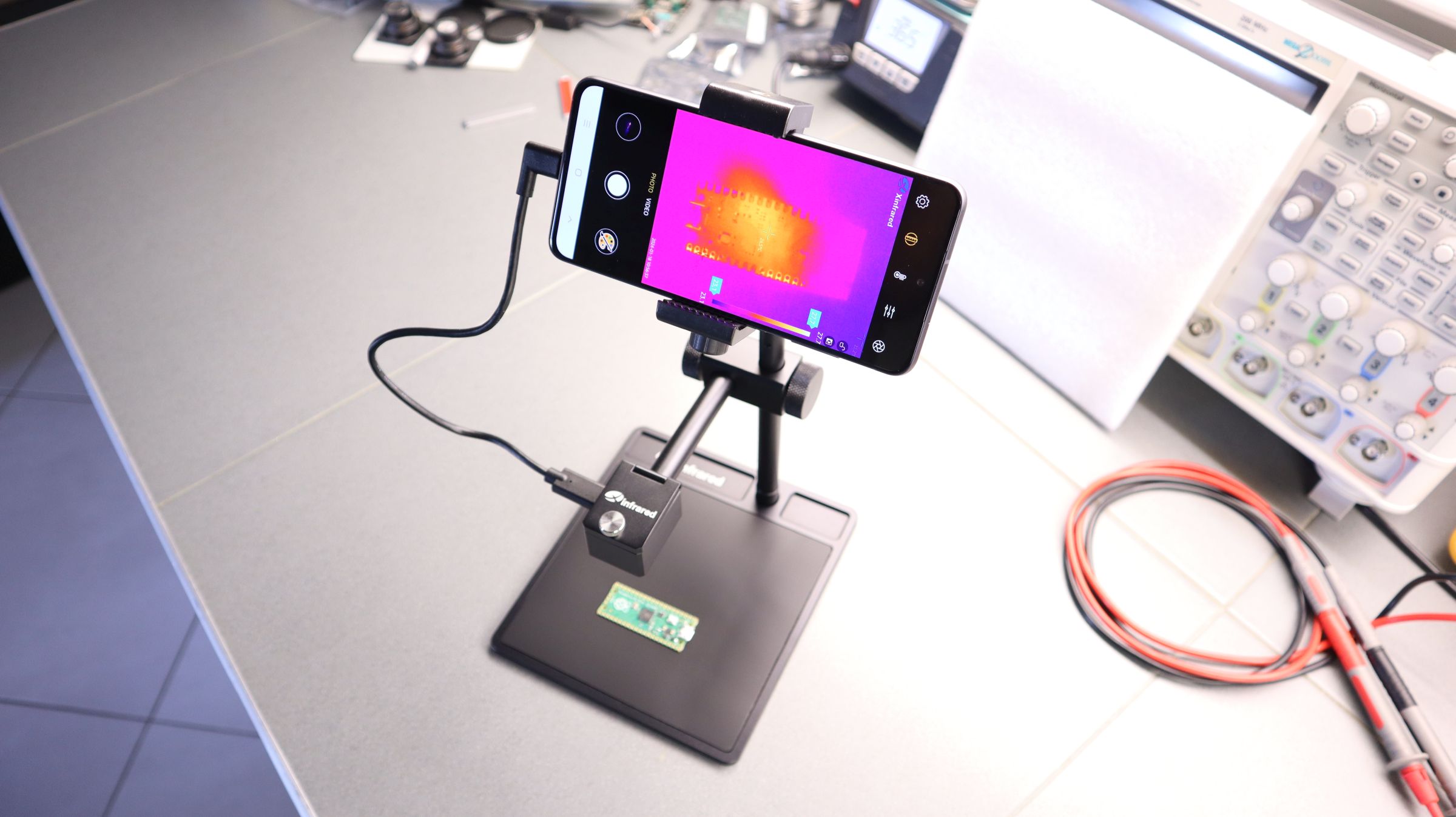
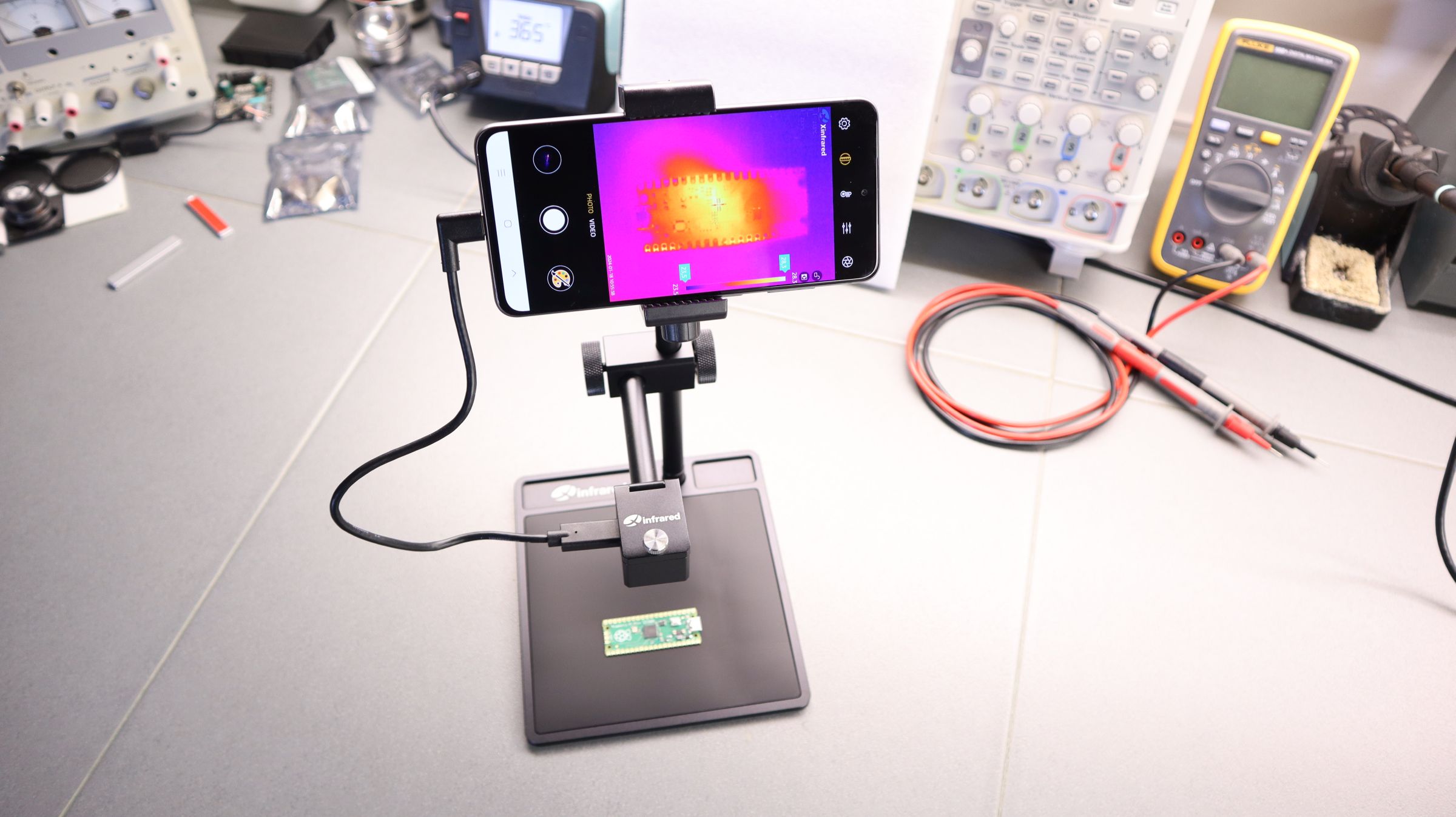
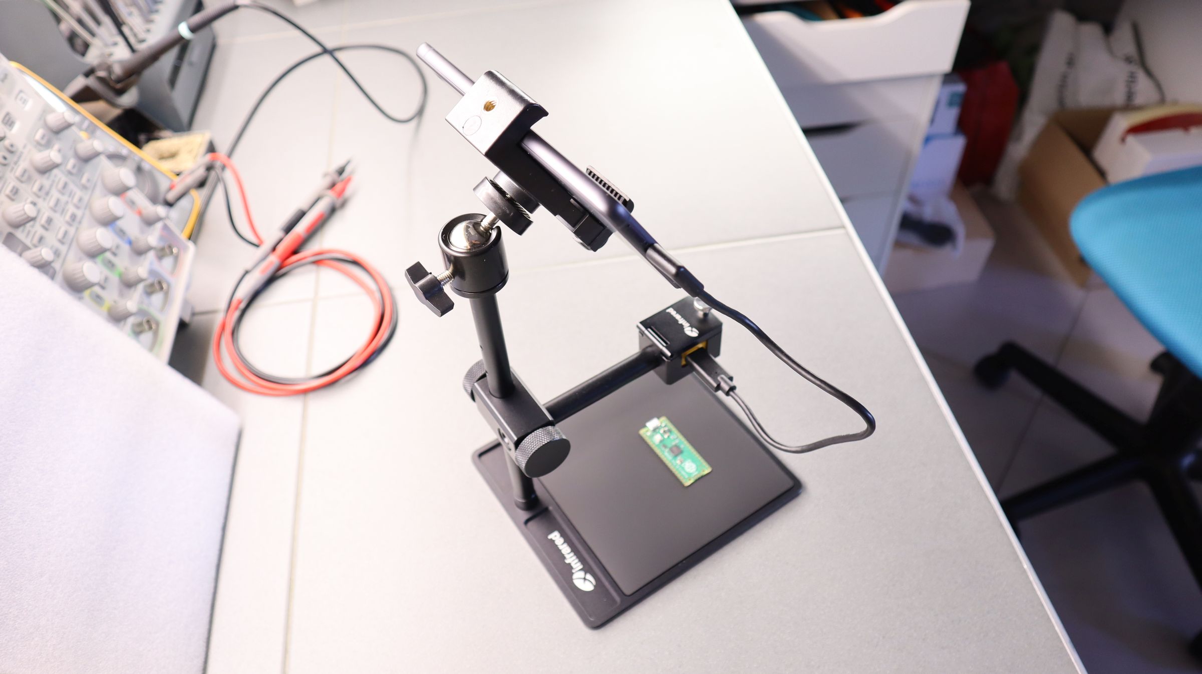
This product also comes with additional accessories (which can be separately purchased) like a camerahold, a metallic phone + camera mount, and an additional handle to mount the phone and camera holder together. With the help of the phone + camera mount, you can also attach the camera to your tripod. With the help of the camera measurement holder, you can easily convert it to a PCB inspection instrument, as you see in the photo below.
Video
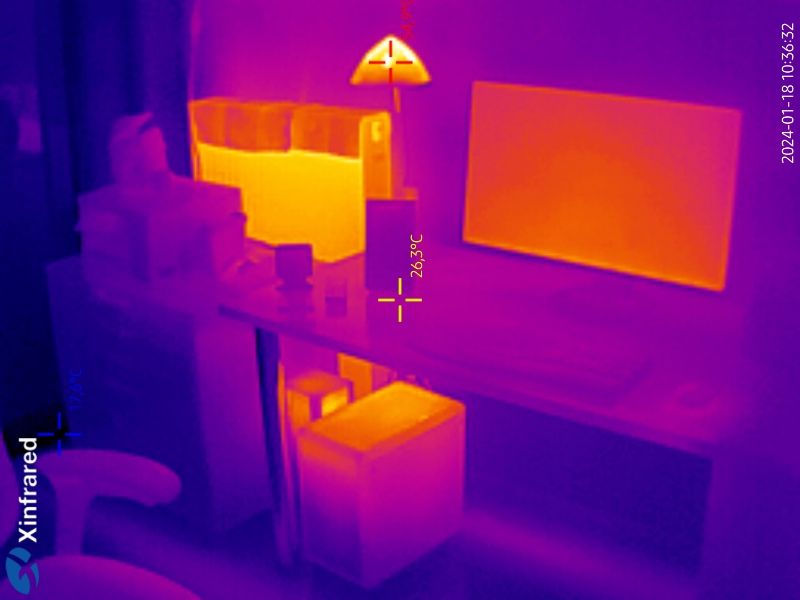
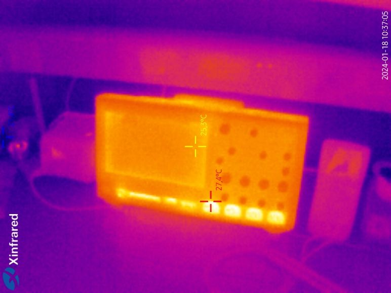
Performance of the Device
To check the performance of the device, we took some photos in our laboratory, and here are the results. As you can see the resolution of the camera is very crisp and using the focusing ring you can take long-distance photos or close-ups of small objects.
InfiRay Xinfrared T2S Plus Thermal Camera Specifications
Product Model: T2S Plus
Lens Type: Macro Lens
Lens Size: 8mm
Resolution: 256×192
Pixel Pitch: 12μm
Field of View (FOV): 44.9° x 33.4°
Image Frame Rate: 25Hz
Noise Equivalent Temperature Difference (NETD): ≤60mK@25°C, F#1.0
Minimum Resolvable Temperature Difference (MRTD): ≤500mK@25°C, F#1.0
Operating Temperature Range: -20°C to +50°C
Temperature Measurement Range: -20°C to +450°C
Measurement Accuracy: ±2°C or ±2% (whichever is greater)
Secondary Development: SDK (Software Development Kit) available
Measurement Statistics: Displays max/min/central point temperatures; provides temperature statistics and analysis for point/line/area
Video Storage: Capable of storing photos and videos
App Update: Online updates available (App Name: Xtherm)
PCB Inspection
As we said earlier the InfiRay Xinfrared T2S Plus can be used as a PCB inspection camera with the help of the aluminum stand that can be separately purchased. This stand holds the camera steady during measurements and can also hold your smartphone or the camera can be connected to your PC and along with the available free software make up a complete thermal inspection unit. Thanks to the manual focus lens you can adapt the camera to work at short distances and thus enable you to inspect single components for heating during a short circuit.
Final Thoughts
The InfiRay XInfrared T2S+ thermal camera is a handy tool for measuring temperature. It’s especially useful for professionals such as electrical engineers and home inspectors, as well as for anyone looking to check for heat leaks at home or to locate pipes and ductwork behind walls. Additionally, it’s compact and priced affordably.
You can buy the Xinfrared T2S Plus at a cool price of $349 from the following stores:
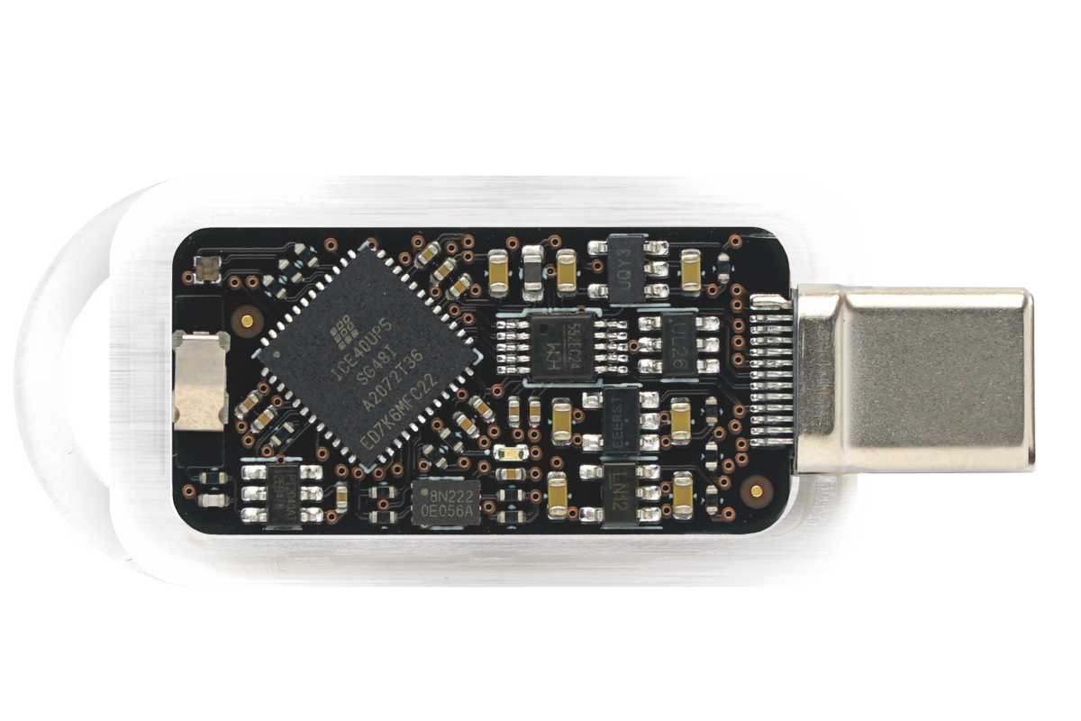
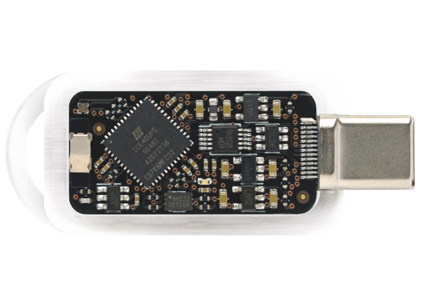
Tillitis Tkey, an open-source RISC-V security key housed in a USB-C case, presents a unique approach to USB security tokens. Compact and straightforward, the TKey employs a 32-bit RISC-V core, specifically the PicoRV32, within a Lattice iCE40 UP5K FPGA.
Distinguished by its departure from conventional hardware security modules, the TKey does not incorporate persistent onboard storage, differentiating itself from alternatives like Yubikey Neo. Upon connection to a host device, applications must be loaded onto the key, leveraging measured boot to generate unique identifiers for each application. This method enhances security, as private keys are not stored on the device. The hardware and software of the TKey are entirely open-source, emphasizing transparency and trustability. Tillitis, a Swedish security firm emerging from the Mullvad VPN company in 2022, derives its name from the Swedish word “tillit,” signifying trust or confidence. The TKey is available in two versions: locked, designed for general users with a fixed configuration, and unlocked, allowing full customization through the Tillitis TK-1 Programmer, based on a Raspberry Pi Pico, catering to advanced users.
TKey comes equipped with a 32-bit RISC-V PicoRV32 core operating at 18 MHz and is integrated into an FPGA, specifically the Lattice iCE40 UP5K. With a TKey device application allocated 128 KiB of RAM, firmware utilizes 2 KiB RAM, and an additional 6 KiB is dedicated to ROM. The device features an execution monitor, and RAM protection, and supports two hardware privilege modes: Firmware mode and application mode. Using a USB-C connector, TKey also incorporates miscellaneous elements such as a touch sensor, power indicator, and status indicator. Operating under a 5V input voltage, the device’s maximum current consumption is 100mA, and it maintains an operational temperature range of 0°C to 40°C.
Various pre-built TKey applications are accessible for download on the company’s website, providing users with convenient options. For those interested in creating their device and client applications, the comprehensive TKey Developer Handbook offers valuable insights. The Tillitis TKey operates on a completely open-source basis, with all software, firmware, Verilog source code, schematics, and PCB design files available in the GitHub repository for transparency and customization.
The TKey RISC-V security key is available in two versions, catering to both end-users and advanced users. Both versions, priced at 880 Swedish krona (approximately $90), can be purchased directly from the Tillitis shop. Additionally, for users seeking enhanced configurability, the programmer is offered separately for 500 Swedish krona, or around $50.
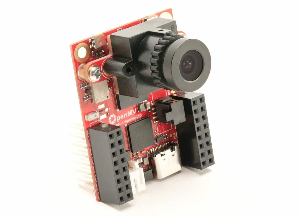
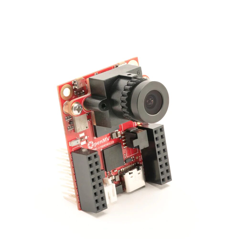
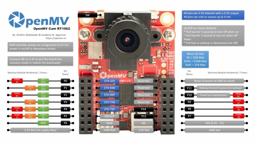
The OpenMVCAM RT1062 is a new camera from OpenMV that uses the powerful NXP RT1060 processor. You can write programs for it using MicroPython, a beginner-friendly version of Python. It has a fast USB-C connection, making it easy to connect to other devices. It also comes with an accelerometer, a sensor that can detect movement or tilting, which can be useful for keeping pictures steady. Another feature is the LiPo connector, allowing it to be powered by a rechargeable battery for portability. Overall, it’s a handy camera for simple programming and capturing motion.
Similar to its earlier version, this camera module has a removable camera system and is built around the OV5640 image sensor, offering improved resolution and versatility. However, the previous Omnivision OV7725 sensor used in the OpenMV Cam H7 outperforms in terms of frame rate and low-light performance.
OpenMV provides a Generic Python Interface Library for USB and WiFi communications, and an Arduino Interface Library for I2C, SPI, CAN, and UART communications. These libraries enable users to connect their OpenMV Cam to other systems easily. To program the board, you have the option of using MicroPython 3 with OpenMV IDE. Alternatively, if you prefer programming in C, you can also use it for programming the device.
OpenMV CAM RT1062 camera Pinout Diagram
The OpenMV Cam RT1062 comes equipped with several notable features:
Processor and Memory:
Powered by an ARM Cortex M7 RT1062 processor clocked at 600 MHz, featuring a 32-bit Cortex-M7 CPU with Double Precision FPU.
1 MB SRAM for efficient memory processing.
External 16-bit, 32MB SDRAM with a bandwidth of 320MB/s.
16 MB QuardSPI flash with a fast 66MB/s read speed.
I/O and Power:
3.3V tolerant I/O pins for versatile connectivity.
High-speed USB-C interface (480Mbps) supporting Virtual COM Port and USB Flash Drive functionality.
Micro SD Card socket with a read-write speed of 25MB/s, featuring EMI Filtering and TVS protection.
Multiple communication buses, including SPI, I2C, CAN, and Asynchronous Serial Bus.
12-bit ADC with 3.3V tolerance.
Three I/O pins dedicated to servo control.
Additional I/O pin for frame sync/triggering.
Low power wakeup I/O pin.
Power button ON/OFF pin.
14 I/O pins with interrupts.
Indicator RGB LED for Charging, USB Power, and VIN Power.
1.5A current limit with EMI Filtering and TVS protection.
Connectivity Options:
Onboard WiFi (a/b/g/n) and Bluetooth (v5.1) with chip antenna and U.FL antenna option.
10/100 Mb/s Ethernet with PoE support via an external shield.
Real-Time Clock (RTC) with low-power mode (under 30uA draw).
LiPo battery connector (3.7V) with USB charging (100 mA Fast Charge) and TVS Protection.
ARM 10-pin JTAG Header compatible with SEGGER J-Link.
External 5V VIN with reverse supply and EMI Protection.
User-controllable RGB LED.
Cryptographic Authentication and Secure Element support with SE050C1HQ1.
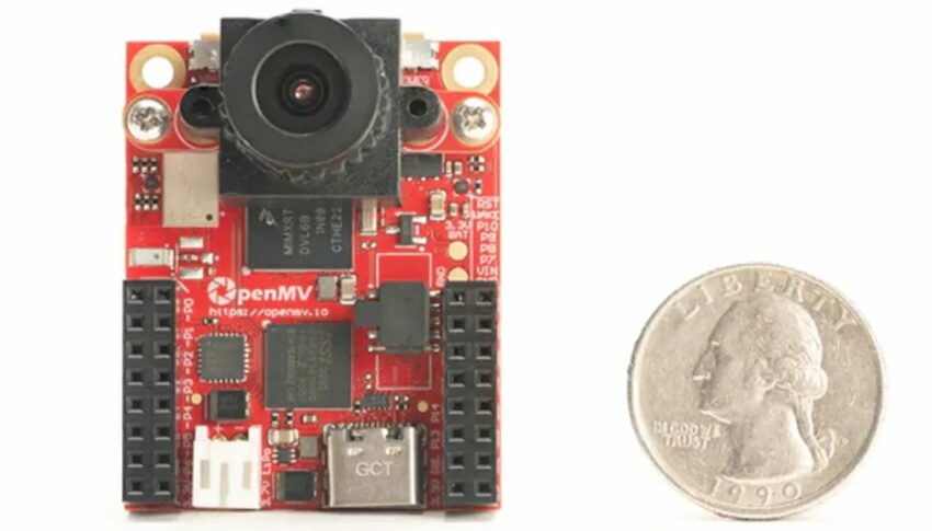
Physical Dimensions and Weight:
Weight: 20g.
Length: 45mm.
Width: 36mm.
Height: 29mm.
Temperature Range:
Storage: -25°C to 85°C.
Operating: 0°C to 70°C.
The company offers a wealth of technical resources, including schematic board references, software application notes, and various technical documents. The product page highlights diverse applications supported by the OpenMV CAM, such as Color Tracking, Marker Tracking, Face Detection, Eye Tracking, Person Detection, Linear Barcode Decoding, AprilTag Tracking, Line and Circle Detection, image capture, video recording, and more.
Priced at $130, the OpenMV Cam RT1062 is currently accessible on the OpenMV website. The initial batch comprises 2,500 units, and shipping has recently commenced, marking the availability of this advanced camera module for interested users.
Arduino and Silicon Labs are working together to support Matter, a standard for smart home devices. They are creating a new core (software foundation) and library following Matter standards. This effort is designed to make it easier for everyone to be part of the Matter ecosystem.
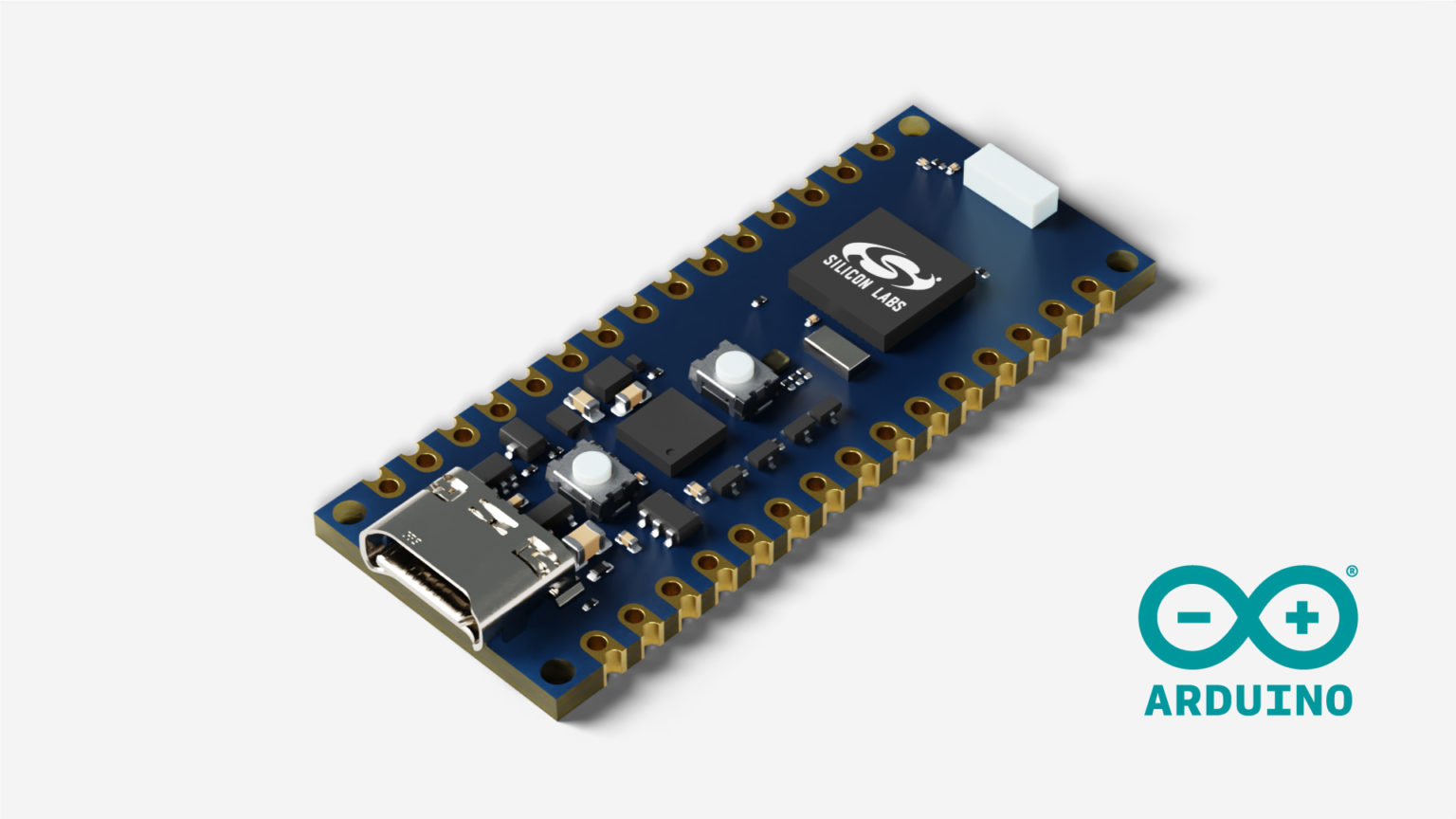
Additionally, they plan to release a new version of the Arduino Nano with built-in support for Matter. This means that developers and hobbyists can easily use the Arduino Nano to create smart home applications that align with the Matter standards. In simpler terms, they’re making it more accessible for people to join and contribute to the world of smart home technology using Arduino devices.
“Our partnership with Arduino brings simplicity and ease of use to wireless development for Silicon Labs developers as well as Arduino’s 40 million users to take their project from concept to production,” claims SiLabs’ Rob Shane of the collaboration between the two companies. “By integrating Matter with Arduino’s ecosystem, we’re opening a universe of possibilities for developers.”
Arduino has partnered with Silicon Labs to make the new Matter standard more accessible in the world of Internet of Things (IoT). They plan to achieve this by introducing a Matter-compliant library for Arduino, making it easier for developers to work with the new standard. Additionally, they have offered a sneak peek at an upcoming Arduino Matter board, suggesting that new hardware is in the works to support Matter connectivity and interoperability. This collaboration aims to broaden the adoption of Matter in IoT applications, providing developers with the tools and resources they need for seamless integration.
SiLabs’ Rob Shane emphasizes that this partnership simplifies wireless development for Silicon Labs developers and opens up new possibilities for Arduino’s vast user base of 40 million. By integrating Matter with Arduino’s ecosystem, the collaboration aims to streamline the process of taking projects from concept to production.
“We are thrilled with the continued adoption of Matter to support IoT applications. The Matter implementation in Arduino has been a massive undertaking and it will make Matter even more accessible for engineers, creators, and innovators across the globe,” says SparkFun chief executive officer Glenn Samala of the launch. “This is another major step forward in interoperability and improving our daily interactions with the devices we have come to rely upon.”
The SparkFun board is not going to be the only option for long. Arduino has hinted at the release of a new Arduino Nano board, utilizing SiLabs’ MGM240SD22VNA microcontroller, which Arduino describes as providing “unparalleled ease of use and capabilities.” The launch is scheduled for March of this year, although the price has not been confirmed yet.
Arduino collaborates with Silicon Labs to provide official support for the Matter standard and hints at the release of a new Arduino Nano
According to the Arduino team, this upcoming board is expected to offer an exceptional opportunity for educators, students, hobbyists, and professionals to engage in IoT projects more easily and with more powerful tools. They anticipate significant implications for smart home applications, industrial IoT, and educational projects.
The SiLabs Arduino core is already available on GitHub. It is compatible with the SparkFun Thing Plus Matter board and SiLabs’ xG27 Dev Kit, xG24 Explorer Kit, and BGM220 Explorer Kit development boards. The Matter library is integrated into the core, but as of now, it only supports the SparkFun Thing Plus Matter and SiLabs xG24 Explorer Kit boards.
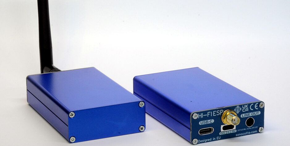
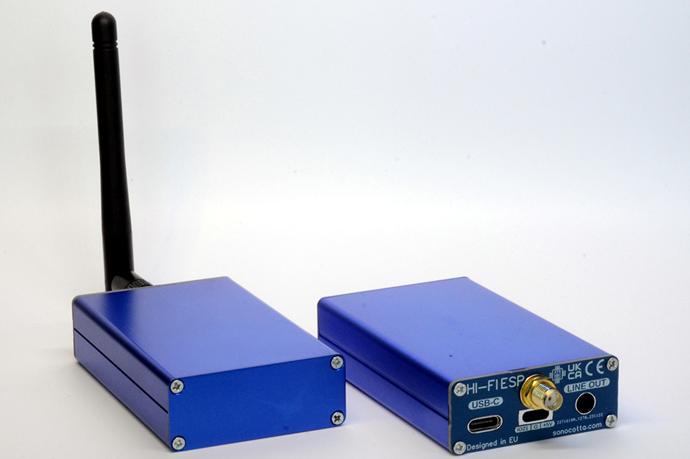
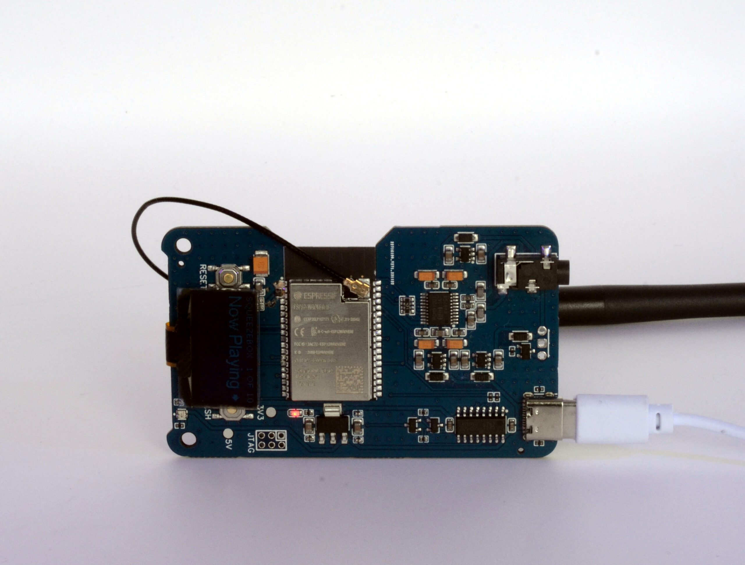
The Esparagus HiFi MediaLink is a device designed to upgrade legacy stereo systems into an internet streaming device. The device hosts an ESP32 module and a DAC to stream music from services like Spotify, controlled via a smartphone or computer.
This tiny and unique streaming device is designed by a Polish designer goes by the name of Sonocotta. In his post, he goes on and say,
I did few audio projects in the past, some using ESP32, some using larger Orange Pi and Raspberry Pi devices. Each has its pros and cons, and each iteration I’m trying to focus on the details that were working best for me, while actually using them.
The device features an ESP32-WROVER module with dual-core 240MHz LX6 processors and 4MB PSRAM for audio buffering, coupled with a Texas Instruments PCM5100A DAC for 2.1 VRMS audio output via a 3.5mm jack.
The Esparagus module connects to speakers or hi-fi audio system, through a 3.5mm jack, and it is powered by a USB Type-C port. Additionally, it includes an external antenna connector for robust metal box housing.
In his post, he goes on and explain the device’s unique name, “Esparagus,” which was suggested by ChatGPT when creator Malyshenko asked for a fruit or vegetable name sounding similar to ESP32, the core component of the device.
Key Features of the Esparagus HiFi MediaLink
Device: Esparagus HiFi MediaLink, for upgrading legacy stereo systems.
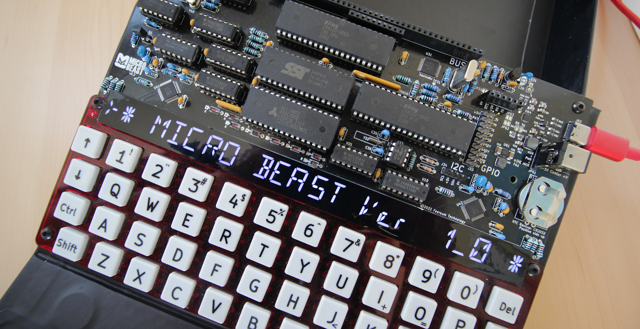
MicroBeast is an eight-bit, Z80-based DIY computer kit built using readily available components. The device features a built-in keyboard, a unique 24-character display, USB-C for power, and various I/O options. Additionally, it integrates the CP/M operating system, which allows users to experience building and operating a retro-style computer using currently available components.
As an embedded engineer we all have worked with 8-bit computers, like Arduino, PIC, and many other controllers and processors. but most of those processors are overkill and include a lot of features that we often don’t use, but that is not the case for Andy Toone’s eight-bit MicroBeast Computer Kit.
The Z80 chipset is a famous microprocessor developed by Zilog in the late 1970s. It was a well-known CPU used in early computers, gadgets, and embedded computers. It was more advanced than similar chips of its time and played a big role in the early days of personal computers.
The Z80 CPU operates at 8 MHz and has 512 KB of RAM and 512 KB of Flash ROM. This ROM contains the CP/M operating system and a built-in monitor utility for managing low-level tasks. For I/O, it features a Z80 Parallel I/O (PIO) chip with two 8-bit ports, 12 GPIO pins, and a software-driven I2C interface, which is primarily used for the display and a real-time clock.
The MicroBeast includes a 16550 UART for serial communication, connecting to both an FTDI-style header and a USB-C interface via a CP2102N converter. Additionally, it features an RC2014-compatible expansion header, allowing expansion cards to directly access the Z80 CPU’s bus.
MicroBeast can be powered via USB-C or an auxiliary barrel jack. Additionally, there’s a work-in-progress emulator, BeastEm, which mirrors the MicroBeast’s core functionality, helping users evaluate the computer kit.
Features and Specifications of MicroBeast 8-Bit Computer Kit
Power: USB-C for power and data; auxiliary barrel jack also available.
Operating System: Running CP/M 2.2.
I/O Options:
GPIO Header with 12 I/O pins.
FTDI port.
Speaker output.
I2C Header for controlling I2C devices.
RC2014 compatible expansion bus.
Connectivity: USB-C for power and serial communication; built-in serial to USB adapter.
Assembly: Comes with all components; PCB with surface mount parts pre-assembled; includes schematics and assembly guide. Requires basic soldering equipment and skills.
Additional Features:
Battery-backed real-time clock.
Laser-cut keyboard frame.
Kit is designed for expansion, customization, and hacking with full access to the CPU bus.
The MicroBeast kit can be pre-ordered on feertech.com, offered on a first-come, first-served basis with an estimated lead time of two weeks. It is priced at $240, with regional equivalents being £190 and €220.