Displays have over time, emerged as one of the best ways to drive user interactions on any device. They make it easy to collect inputs and present information (outputs) to users in a graphical, easy to understand format. This usefulness has led to improvements in their quality, with improved resolution and low power features, but almost little has changed when it comes to the complexity of creating beautiful user interfaces for them. This is why the team at STONETech created the STVC035WT-01 intelligent Smart display which we will explore for today’s tutorial.
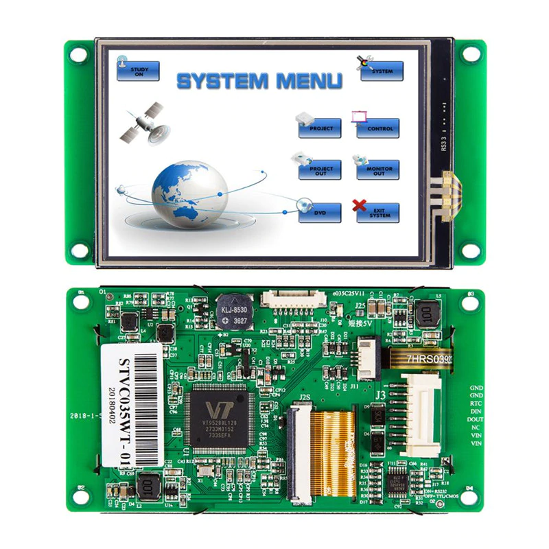
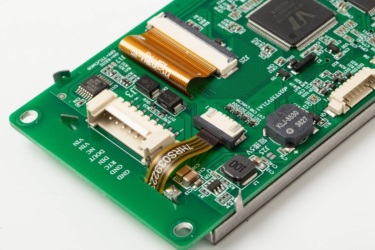
The STONETech STVC036WT display is a 16-bit, 3.5″ display with a 320×480 (RGB) resolution, has a 49.0 x 73.4mm viewing area, and pixel spacing of 0.1905mm×0.0635mm (H×V). The display is a Class A industry Panel with an Industry level 4 wire resistance based touch screen, all layered on an integrated CPU, driver, and flash memory with several communication interfaces to enable it to connect to data sources like microcontrollers. For communication with a microcontroller, the display supports serial communication protocols like UART/TTL, RS232, and RS485, ensuring it can communicate with any kind of microcontroller or industrial computers. The UART/TTL pin on the Display supports both 3.3v/5v logic level which adds another layer of ease to the use of the display as users need not worry about the need for logic level shifters when building using a microcontroller that operates on either of the voltage level mentioned.
How to use STONEtech STVC035WT-01 intelligent TFT LCD module with Arduino – [Link]
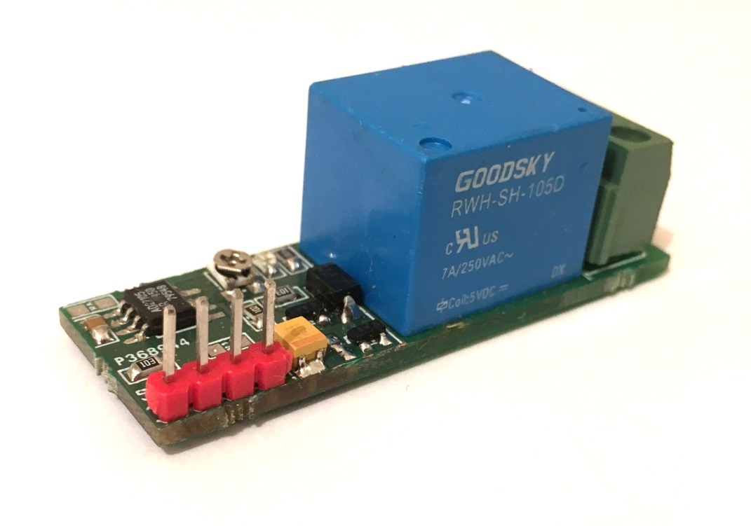
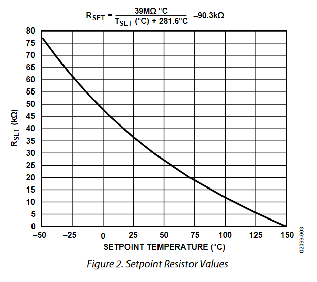
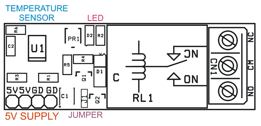
This project simply switches the system OFF or ON whenever the temperature rises at the desired set point. The desired setpoint can be set using a fixed resistor R6 or PR1 trimmer potentiometer. Use any of at a time R6 or PR1. You can calculate the setpoint resistor R6 using the following equation.
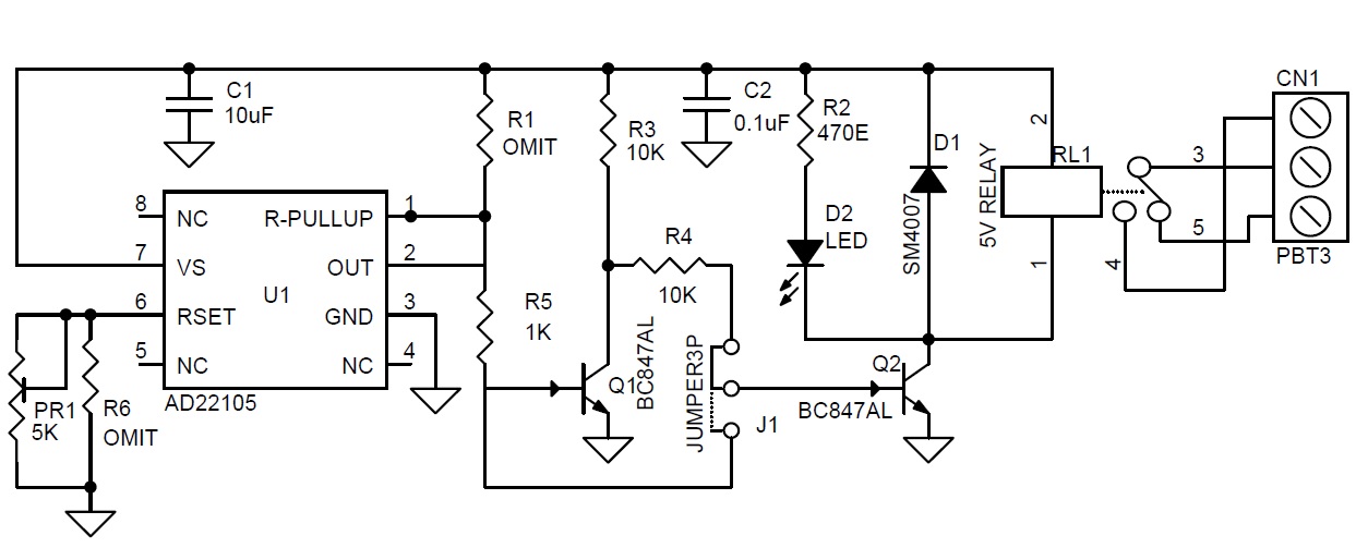
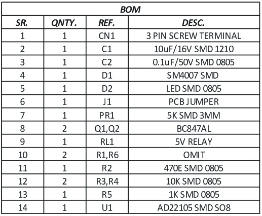
A relay is provided to switch ON or OFF the load. The relay can switch 7Amps/250V AC load. D2 LED indicates the relay operation. J1 provided to choose normally closed or open options for the relay. This project is built using AD22105 IC from Analog devices. The AD22105 is a single-supply semiconductor thermostat switch that uses circuit architecture to realize the combined functions of a temperature sensor, set point comparator, and output stage all in one IC. By using one external resistor or trimmer pot, the AD22105 can be programmed to switch at any temperature selected by the system designer in the −40°C to +150°C range. The internal comparator is designed to switch accurately as the ambient temperature rises past the set point temperature. When the ambient temperature falls, the comparator relaxes its output at a somewhat lower temperature than that at which the comparator originally switched. The difference between the switch and un-switched temperatures, known as the hysteresis, is nominally 4°C.
Programmable Thermostatic Switch using AD22105 – [Link]
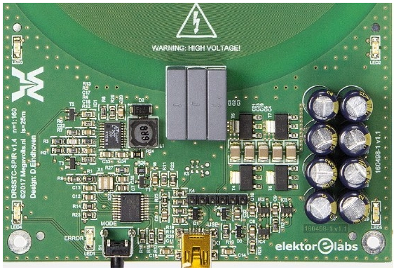
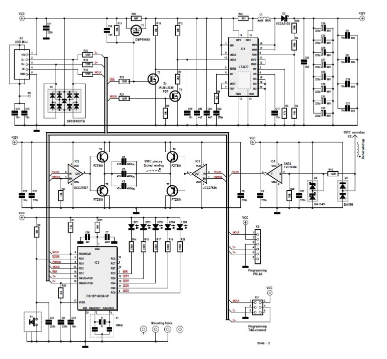
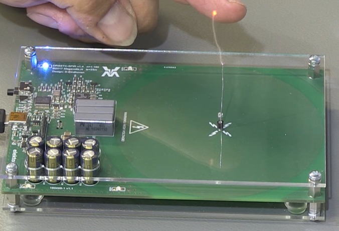
Original publication: Elektor magazine 6/2017, page 58. Author: Daniel Eindhoven.
Free download expires Friday 27 December 2019.
1. Introduction
It seems to be an unwritten rule in Hollywood: there must be an assortment of devices that crackle and spark in the lab of a mad scientist. It doesn’t matter that all those noises and flashes have no apparent purpose, as long as the effects look spectacular!
Displays have over time, emerged as one of the best ways to drive user interactions on any device. They make it easy to collect inputs and present information (outputs) to users in a graphical, easy to understand format. This usefulness has led to improvements in their quality, with improved resolution and low power features, but almost little has changed when it comes to the complexity of creating beautiful user interfaces for them. This is why the team at STONE Tech created the STVC035WT-01 intelligent Smart display which we will explore for today’s tutorial.
The STONE STVC035WT-01 display is a 16-bit, 3.5″ display with a 320×480 (RGB) resolution, has a 49.0 x 73.4mm viewing area, and pixel spacing of 0.1905mm×0.0635mm (H×V). The display is a Class A industry Panel with an Industry level 4 wire resistance based touch screen, all layered on an integrated CPU, driver, and flash memory with several communication interfaces to enable it to connect to data sources like microcontrollers. For communication with a microcontroller, the display supports serial communication protocols like UART/TTL, RS232, and RS485, ensuring it can communicate with any kind of microcontroller or industrial computers. The UART/TTL pin on the Display supports both 3.3v/5v logic level which adds another layer of ease to the use of the display as users need not worry about the need for logic level shifters when building using a microcontroller that operates on either of the voltage level mentioned.
A summary of the features and specification of the display are shown below:
Cortex m4 CPU
UART interface (RS232/RS485/TTL) ;
256-byte register;
128 kb variable memory;
128 MB flash memory, expandable to 1 GB;
GUI design software;
A customized command set;
8-channel curve trend chart memory;
extremely fast variable display response speed;
A single-page supports up to 128 display variables;
Integrated real-time clock RTC,
Touch buzzer sound function;
Support software 90 degrees, 180 degrees, 270 degrees screen rotation, adjust the appropriate visual Angle;
One of the major benefits of using this display is its compatibility with the STONE TOOL GUI Designer which allows the development of User Interfaces in a fast and easy manner.
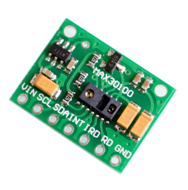
To demonstrate the capabilities of the display, we will build a heart rate monitor using an Arduino Uno with the MAX30100 pulse oximetry and heart rate sensor. The Arduino will serve as the brain of the project and perform the simple task of obtaining the heart rate and blood oxygen data from the MAX30100, displaying it on the screen.
At the end of this tutorial, you would know how to interface Arduino boards with the STONETech displays, and also how to interface sensors like the MAX30100 with the Arduino.
Required Components
The following components are required to build this project;
Arduino Uno
STVC035WT-01 (or any other STONE Tech display)
MAX30100 Pulse Optometry sensor
MAX3232
Bread Board
Jumper Wire
Power Bank/Battery with a 9v Jack
MAX30100 Sensor
Creating the GUI
There are 2 major steps associated with the development of devices using any of the STONEtech displays:
Creating the GUI using the STONE GUI Design Tool and exporting the GUI to the display.
Connecting the display to the microcontroller and writing the code to integrate the microcontroller with the display.
Our development process for today’s project will follow this outline. We will first create the GUI for the project after which we will proceed to write the firmware to interface the microcontroller with the display.
1. Creating the GUI using the STONE TOOL GUI Designer
There are two major ways of creating a GUI. One is to create the GUI using only the elements (buttons, text boxes, etc) that are available within the GUI Design tool, while the second is to create a mockup image using image editing tools like Photoshop/Paint.NET, import the image into the GUI Desing tool software and place the GUI design elements on the image. For this tutorial, we will go with the second option as it allows more flexibility and gives room for the development of truly beautiful GUIs.
As mentioned during the introduction, today’s tutorial will focus on creating a heart rate and Oxygen-level monitoring system using the display and to get things started, we create the GUI image (shown below) using Photoshop.
The design is quite simple, we illustrate label elements to hold the date, the project title, and the values from the microcontroller. The values from the microcontroller include; the status of the connection between the microcontroller and the display, the heart rate, and the oxygen levels.
With the GUI Image done, we then proceed to import it into the STONE TECH GUI tool. This obviously mean we need to install the STONE TOOL first, so head over to the STONE Tool GUI Designer page and download it. The STONE TOOL software requires no installation and it can be directly opened and run by decompression on your computer.
It should be noted that while compatibility with other OS is currently being considered, the current version of the software only supports Windows 8and 10 operating systems.
Follow the steps below to create the GUI.
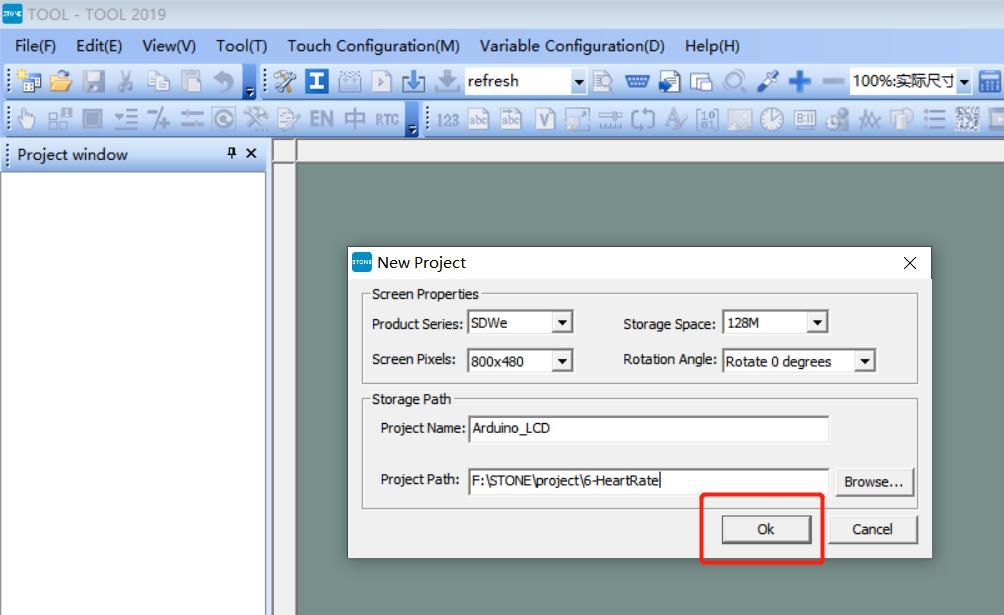
1. With the software downloaded on your computer, launch it and go to File>New Project. This will launch the “New Project dialog box ” where you will be expected to fill in the details of your display, set the storage path, and the name of your project. Since we will use the STVC035WT-01 display which has a resolution of 320*480 and a default flash space size of 128Mbyte (expandable to 1024MByte), I have entered its details as shown in the image below. If you are using any of the other StoneTech displays, you will need to enter the details of that display instead.
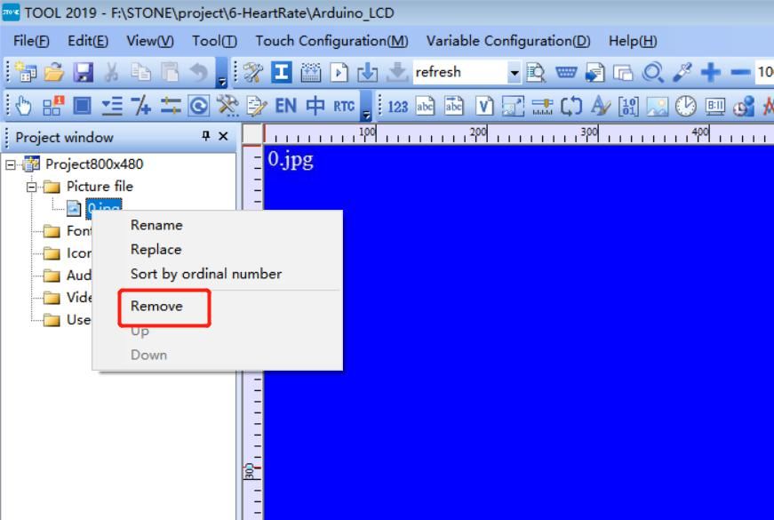
2. Next, on the left side of your screen, you will see the project tree (under the project window) with its assets. Expand the Picture file, and delete the 0.jpg image inside it by right-clicking on it, and selecting “Remove”. For every new project, the 0.jpg file is always created as the default background for your UI, since we will use our background (the one we designed with photoshop), we can delete it.
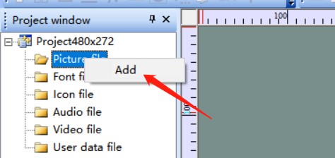
3. Next, we need to add the background we designed with photoshop into the picture file. Right-Click on the “Picture” directory and select “Add”. This will open a dialog box for you to navigate to where the JPG version of our photoshop images is stored.
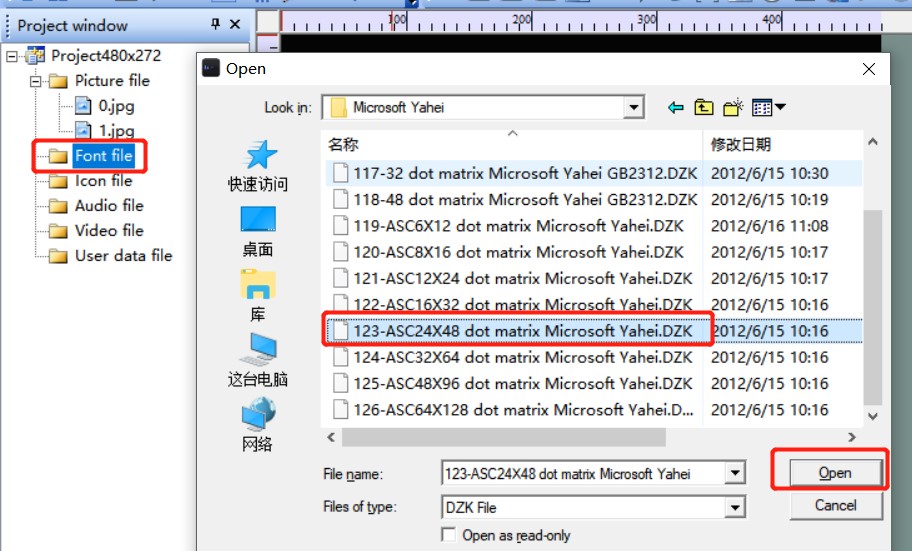
4. Next, we add fonts to the project’s assets to determine how texts appear on the display. Right-click the “Font” file, and select the appropriate font to add to the project. For this tutorial, we will use the ASCII 24 by 48 font. With that done we are now ready to begin adding the GUI elements.
5. We will only use the “Text Display” GUI element since the display is only meant to display data from the MAX30100. The text display elements are capable of holding texts that can be changed programmatically by updating the data stored in their memory addresses. Add text displays on the lines as highlighted in the image below. Also, create a text display for the day-time section at the top of the display image to help users note the date/time each reading was observed.
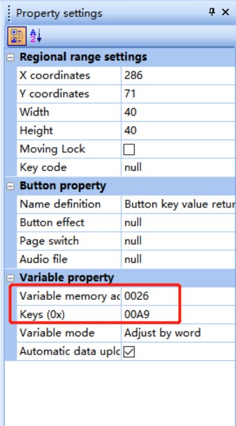
6. Next, we set the properties of the text displays especially their memory addresses. The properties of each GUI element will be available on the right-hand side of your PC screen after clicking on the element. Note the memory address down as it will play an important role later.
Copy Memory Address
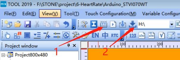
7. With all of these done, we compile the GUI and upload it to the screen. To do this, click on button 1 in the image below to Compile the GUI design and click on button 2 to upload the GUI to your display.
Compile and Upload GUI
Uploading the GUI display requires you either connect the display directly to your computer or you put the GUI on a flash drive and plug the flash drive into the USB port of the display. Because of the little complexity associated with the second option, we will be going with it.
Plug the USB flash drive into the computer then click the “Download to u-disk” button on the STONE GUI TOOL. With the “download to u-disk” process complete, pull out the USB flash disk, insert it into the USB interface of the display module and wait for the completion of the upgrade. When the upgrade is completed, there will be a prompt sound.
With the GUI uploaded to the display, we can now connect the display and other components and write the Arduino code to publish data to it.
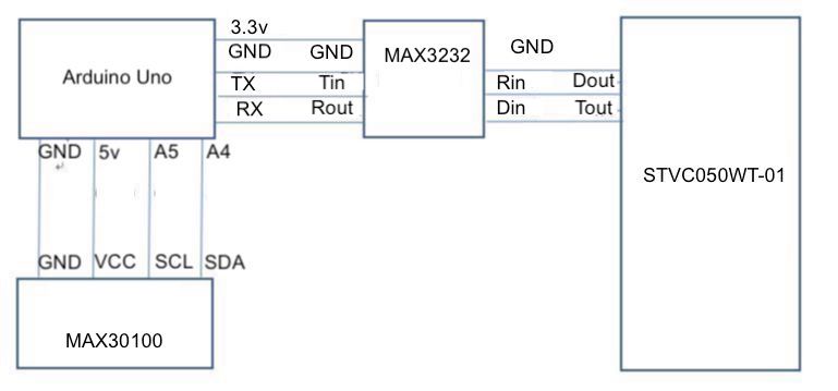
Schematics
Connect the display and the MAX30100 to the Arduino as shown in the image below.
Schematics
The model of the STONE display being used for this tutorial communicates via RS232, as such, to be able to interface the display with the Arduino, we have to connect it through a MAX3232 chip. This extra requirement can be avoided by using one of the STONE displays with a TTL interface.
To make the schematics easier to follow, a pin-to-pin map showing how each of the components connects, one to the other, is provided below.
STVC035WT-01 – Max3232
Din - Rin
Tout - Din
GND - GND
Max3232 – Arduino
Rout - RxD
Tin - TxD
GND - GND
VCC- 5v
MAX30100 – Arduino
SDA - A4
SCL - A5
GND - GND
VCC- 5v
Go over the connections once again to be sure everything is properly connected. With this done we can now proceed to the Arduino code to send commands and data to the LCD.
Arduino Code
The idea behind the Arduino code is to condition the data from the MAX30100 and create a pipeline for the data to be sent to the LCD display.
Due to the simplicity embedded in the design of STONETECH displays, the microcontroller’s interaction with any of the GUI components is usually via the “memory address” of each component. for instance, to send a message to the display from the microcontroller (the Arduino in this case), the message has to be published to the memory address of the GUI Component (in this case, the text-display component). The same holds for GUI Components that are meant to send data to the microcontroller, as the microcontroller has to poll their memory address to obtain information from them. As a result of these, we need to obtain the memory address of all the GUI components before proceeding. For each GUI component, the memory address is usually listed among the properties of the component, under the property toolbar, at the right-hand side of the STONE TOOL interface.
While mine may be different from yours, the memory address of the text displays is provided below.
Connection sta : 0x0008
Heart rate : 0x0001
Blood oxygen : 0x0005
With this obtained, we can now proceed to write the code for the project. One of the good things about using the STONETech displays is the fact that you don’t need a library to write code for them because of their simplicity, but since we will use serial communication, we will use the software serial library to avoid having to use the hardware serial port on the Arduino Uno. To interface with the MAX30100, we will also need to install the MAX30100 library. The Max30100 library can be installed using the Arduino Library Manager or by downloading it from the attached link and installing manually by extracting the file, copying its content and pasting it in the Arduino libraries folder. The software serial library comes pre-installed with the Arduino IDE.
>With the libraries installed, we now have all we need to write the Arduino Code. As usual, I will do a brief explanation and attach the complete version of the code under the download section.
We start the code by including the libraries we will use. The Wire.h library is added to satisfy the I2C requirements of the Max30100 library.
Next, we provide the customized commands that will be sent to the screen to store data in the memory address. The commands are the same for all the elements with the only difference being the memory address.
Next, we specify the variables; Reporting_Period_MS and tsLastReport, which will be used to determine when the sensor should be refreshed. With this done, we then move to the void setup() function.
We start the function by initializing serial communications between the screen and the microcontroller setting the baud rate to 115200. We also initialize hardware serial communication so we can use the serial monitor on the Arduino IDE for debugging purposes.
Next, we initialize the MAX30100 and send the status of the initialization to the display. If the initialization fails, 0x00 meaning 0 is sent to the display, but if successful, 0x01 meaning 1 is sent to it.
To wrap up the void setup() function, we increase the current of the IR LED on the Max30100 beyond the default 50mA. With this done, we move to the void loop() function.
// The default current for the IR LED is 50mA and it could be changedby uncommenting the following line. Check MAX30100_Registers.h for all theavailable options.
pox.setIRLedCurrent(MAX30100_LED_CURR_7_6MA);
}
We start the void loop() function by calling for updated readings, after which we check if the reporting period has elapsed. If the reporting period has elapsed, it means we need to take new measurements, so we call the pox.getHeartRate and pox.getSp02 commands to get new heart rate and oxygen levels. These new readings are displayed on the serial monitor and also sent to the display.
void loop()
{
// Make sure to call update as fast as possible
pox.update();
// Asynchronously dump heart rate and oxidation levels to the serial
// For both, a value of 0 means "invalid"
if (millis() - tsLastReport > REPORTING_PERIOD_MS)
{
Serial.print("Heart rate:");
Serial.print(pox.getHeartRate());
Serial.print("bpm / SpO2:");
Serial.print(pox.getSpO2());
Serial.println("%");
heart_rate_send[7]=(uint32_t)pox.getHeartRate();
screenserial.write(heart_rate_send,8);// send heart rate to display
Sop2_send[7]=pox.getSpO2();
screenserial.write(Sop2_send,8);// send oxygen level to display.
tsLastReport = millis();
}
}
The complete code for the project is provided below and also attached under the download section of the tutorial.
#include <Wire.h>
#include <SoftwareSerial.h>
#include "MAX30100_PulseOximeter.h"
SoftwareSerial screenserial(10, 11); // RX, TX
PulseOximeter pox;
#define Heart_dis_addr 0x01
#define Sop2_dis_addr 0x05
#define connect_sta_addr 0x08
unsigned char heart_rate_send[8]= {0xA5, 0x5A, 0x05, 0x82,\
0x00, Heart_dis_addr, 0x00, 0x00};
unsigned char Sop2_send[8]= {0xA5, 0x5A, 0x05, 0x82, 0x00, \
Sop2_dis_addr, 0x00, 0x00};
unsigned char connect_sta_send[8]={0xA5, 0x5A, 0x05, 0x82, 0x00, \
connect_sta_addr,0x00, 0x00};
#define REPORTING_PERIOD_MS 1000

uint32_t tsLastReport = 0;
void setup()

{
  screenserial.begin(115200);
  Serial.begin(9600);
Serial.print("Initializing pulse oximeter..");
  Initialize the PulseOximeter instance
  if (!pox.begin())
  {
    Serial.println("FAILED");
    connect_sta_send[7]=0x00;
    screenserial.write(connect_sta_send,8);

    for(;;);

  }
  else
  {
    connect_sta_send[7]=0x01;
    screenserial.write(connect_sta_send,8);
    Serial.println("SUCCESS");

  }
 // The default current for the IR LED is 50mA and it could be changedby uncommenting the following line. Check MAX30100_Registers.h for all theavailable options.
  pox.setIRLedCurrent(MAX30100_LED_CURR_7_6MA);
}
void loop()
{
  // Make sure to call update as fast as possible
  pox.update();
  // Asynchronously dump heart rate and oxidation levels to the serial
  // For both, a value of 0 means "invalid"
  if (millis() - tsLastReport > REPORTING_PERIOD_MS)
  {
    Serial.print("Heart rate:");
    Serial.print(pox.getHeartRate());
    Serial.print("bpm / SpO2:");
    Serial.print(pox.getSpO2());
    Serial.println("%");
    heart_rate_send[7]=(uint32_t)pox.getHeartRate();
    screenserial.write(heart_rate_send,8);// send heart rate to display
    Sop2_send[7]=pox.getSpO2();
    screenserial.write(Sop2_send,8);// send oxygen level to display.
    tsLastReport = millis();

  }

}
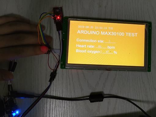
Demo
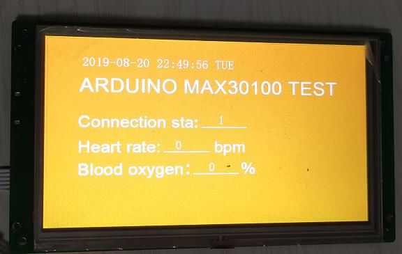
With the code complete, connect your Arduino board to your computer and upload the code to your setup. Place a finger on the Max30100 and after a while, you should see the live pulse rate and oxygen levels appear on the display as shown in the image below.
Demo
While this project only demonstrates less than 35% of the capabilities of the STONE TECH display, it provides a good foundation for you to build amazing projects. As an engineer, the key benefit of the display to me is the ease of use both in the creation of the GUI and also the development of the code to tie it together with a microcontroller. The fact that the display doesn’t require any library makes it perfect for use with any language and any microcontroller with serial port access.
The quality, size ανδ variety of the STONE TECH displays makes them perfect for HMI Applications and one of my next projects will be a Home Automation Panel using one of the STONETECH displays.
Τhat’s it for this tutorial guys. Feel free to reach out to me via the comment section if you have any difficulties with recreating this project.
This project simply switches the system OFF or ON whenever the temperature rises at the desired set point. The desired setpoint can be set using a fixed resistor R6 or PR1 trimmer potentiometer. Use any of at a time R6 or PR1. You can calculate the setpoint resistor R6 using the following equation:
A relay is provided to switch ON or OFF the load. The relay can switch 7Amps/250V AC load. D2 LED indicates the relay operation. J1 provided to choose normally closed or open options for the relay. This project is built using AD22105 IC from Analog devices. The AD22105 is a single-supply semiconductor thermostat switch that uses circuit architecture to realize the combined functions of a temperature sensor, set point comparator, and output stage all in one IC. By using one external resistor or trimmer pot, the AD22105 can be programmed to switch at any temperature selected by the system designer in the −40°C to +150°C range. The internal comparator is designed to switch accurately as the ambient temperature rises past the set point temperature. When the ambient temperature falls, the comparator relaxes its output at a somewhat lower temperature than that at which the comparator originally switched. The difference between the switch and un-switched temperatures, known as the hysteresis, is nominally 4°C.
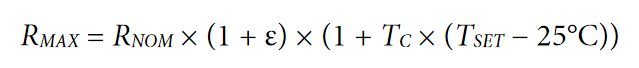
To combine and calculate the initial tolerance and thermal drift effects of the setpoint resistor R6 use the following equation:
RMAX is the worst-case value that the setpoint resistor can be at TSET. RNOM is the standard resistor with a value closest to the desired RSET. ε is the 25°C tolerance of the chosen resistor (usually 1%, 5%, or 10%). TC is the temperature coefficient of the available resistor. TSET is the desired setpoint temperature.
After calculation, compare RMAX to the desired RSET from Equation 1. The required value of RSET at a TSET of 125°C is 5.566 kΩ. If the nearest standard resistor value is 5.600 kΩ, its worst-case maximum value at +125°C is 5.713 kΩ, which is +2.6% higher than RSET, leading to a total additional error of −0.52°C beyond that given in Table 1 in the datasheet.
Such as for inductors, the electrical behavior of capacitors also depends on the nature of the source : DC or AC. We will see through this tutorial that in some way, the capacitor can be seen as the opposite of an inductor in terms of frequency functioning.
Like for the resistors and inductors, we present in a first section the concept of capacitance that will help us to understand why capacitors behave differently in DC and AC regime and by which mechanisms they do it.
In the second section, we talk about the capacitive reactance to understand exactly how capacitors react with an increase of the frequency.
The last section shows how associations of resistors-capacitors or inductors-capacitors work and can be used for filtering applications.
Presentation
The Capacitance
The capacitance (C) is a primary concept to understand on how a capacitor works. It describes the voltage (V) that the component will generate when charged with electrical charges (Q) at its terminals. The most general and natural way to express the capacitance is therefore C=Q/V being expressed in Farad (F).
Before illustrating and giving more details about the capacitance, it is worth to briefly describe what is an electrical charge. Such as the concepts of mass and time, the charge is hard to describe with simple words, it is easy to feel but tricky to define. It is an intrinsic property of elementary particles such as electrons or protons.
When a charge moves it creates a current, the charge of electrons is equal to -e and for protons it is +e, opposite charges attract each other : this is why electrons orbit around atoms without escaping. The official unit to measure a charge is the Coulomb (unit C) and e≅1.6×10⁻¹⁹ C.
Measuring a charge is however not easy nor the method used to determine the capacitance of a particular component. Fortunately, the capacitance can be expressed with another formula presented in the following.
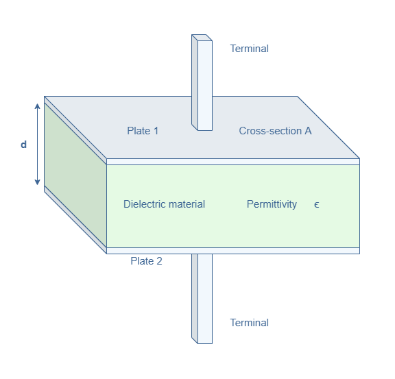
Unlike the resistivity and inductance, the capacitance strongly depends on the geometry considered. The most simple example of capacitor is the parallel plate topology represented in Figure 1. It consists of two conducting plates separated by a thin layer of insulating material (in green).
fig 1 : Parallel-plate capacitor configuration
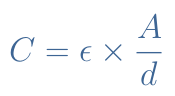
If a potential difference is applied between the plates through the terminals, a charge +Q (resp. -Q) will be formed in the plate 1 (resp. plate 2). The capacitance can in this case be expressed by the following formula :
eq 1 : Capacitance of a parallel-plate configuration
ε is the absolute permittivity and can be decomposed in two factors : ε=ε0×εr with ε0≅8.8×10⁻¹² F/m being the vacuum permittivity and εr the relative permittivity of the insulating material. Materials with higher insulating properties have a higher relative permittivity which increases the capacitance.
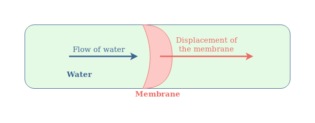
In order to better understand these concepts and how capacitors work, we can define an hydraulic analogy with an elastic membrane inside a pipe such as shown in Figure 2. Hydraulic analogies are a common way to establish correlations between abstract concepts in electricity with a more simple approach in the hydraulic domain.
fig 2 : Hydraulic analogy of the capacitor
In this analogy, the pipe represents the electric wire, the flow of water represents the electricity and the membrane is the capacitor. Moreover, the stiffness of the membrane represents the capacitance.
Such as for the capacitor, the water cannot go through the membrane but its pressure (analogy of the potential) induces a displacement of the membrane. If the water pressure is kept constant in the same direction, the membrane is pushed in the same direction with the same curvature and the molecules of water do not move. However, if an alternating flow of water is given, the membrane is pushed alternatively in opposite directions and the molecules of water are moving around it.
DC and AC regimes
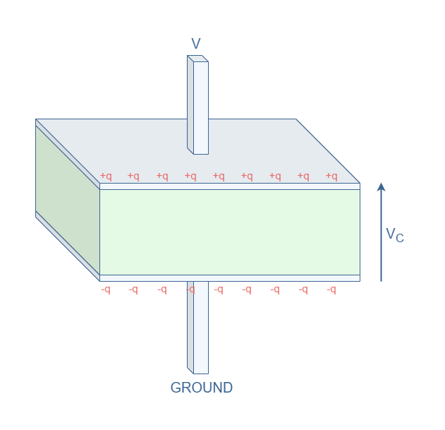
Now that we know more deeply what a capacitance consists of, we need to understand why it’s behavior is different when applying a constant or alternating voltage, which we briefly explained with the hydraulic analogy. Consider the same architecture of capacitance C as presented in Figure 1 when applying a constant potential difference V-VGROUND :
fig 3 : Parallel-plate configuration in DC regime
Due to electrostatic effect, applying a positive voltage V attracts charges +q at the plate 1 and -q at the plate 2. The sum of the positive charges (resp. negative charges) is +Q (resp. -Q). This distribution of charges generates a voltage VC=Q/C in the capacitor.
As long as the capacitor holds the charges, the voltage VC remains stable and we describe this particular state as charged. For perfect capacitors, the voltage VC can remain even if the DC source is turned off. However, in reality, we observe a discharge when the charges redistribute and VC decreases exponentially.
Apart from a temporary current that can be observed when the capacitor discharges (if the source is turned off), IC=0 in DC regime.
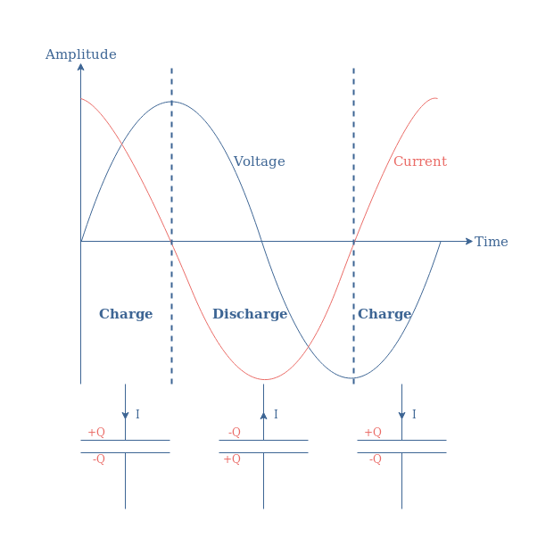
This behavior is however different in AC regime, the Figure 4 below superimpose the voltage and current characteristic along with the distribution of charges in the capacitor :
fig 4 : Charge and discharge cycles in AC regime
When applying an AC voltage to a capacitor, charge and discharge cycles are observed which generates a current that is phase shifted of -90° which is known as a quadrature of phasedelay.
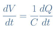
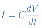
Another more mathematical way to understand the appearance of a current when the frequency increases is with the general relation C=Q/V that can be rewritten V=Q/C.
This relation is differentiable such as shown in the following equation :
By definition dQ/dt=I, therefore, the current (I), voltage (V) and capacitance (C) are linked by the following equation :
eq 2 : Current equation of a capacitive component
With the Equation 2, we can see that no current can be observed if no variation of voltage is present. Moreover, the current increases if the variations are faster, i.e if the frequency increases.
Frequency behavior
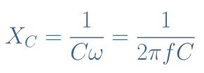
Such as for inductors, the concept of reactance can also be applied for capacitors. It is noted XC and describes the opposition of a capacitive component with a change of voltage. The capacitive reactance is the imaginary part of the complex impedance ZC of a capacitive component : ZC=RC+j×XC.
Actually, the impedance of a capacitor reduces to –jXC since we have seen previously that the phase shift observed in a capacitive component is -90°. We can refer to the tutorial about complex numbers to understand that such a phase shift is only possible if the complex impedance is a pure imaginary number, giving therefore RC=0.
The capacitive reactance satisfies the following Equation 3 :
eq 3 : Reactance of a capacitor
As opposition to the inductors, we can understand through this equation that the opposition to an AC voltage decreases inversely with an increase of the frequency. At f=0, XC→+∞, which means that the capacitor behaves as an open circuit at low frequency. When f→+∞, XC=0, which means that the capacitor becomes a short circuit.
Filters
The different properties of the three basic electric components (R, L and C) can be associated in the same circuit to create filters. In this section, we briefly present the RC and LC filters.
RC filter
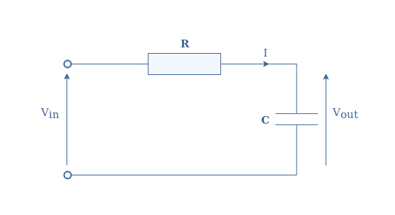
Consider the following circuit in Figure 5 with Vin the input voltage and Vout the output voltage :
fig 5 : Series RC circuit
We use the same technique as shown in the AC inductance tutorial in order to get the gain and phase shift of the circuit with the transfer function.
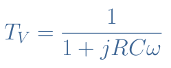
By applying the voltage divider formula, we get the following transfer function TV :
eq 4 : RC circuit transfer function
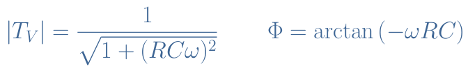
And finally the gain and phase shift of the RC filter is given by |TV| and Φ :
eq 7 : Gain and phase shift of a RL circuit
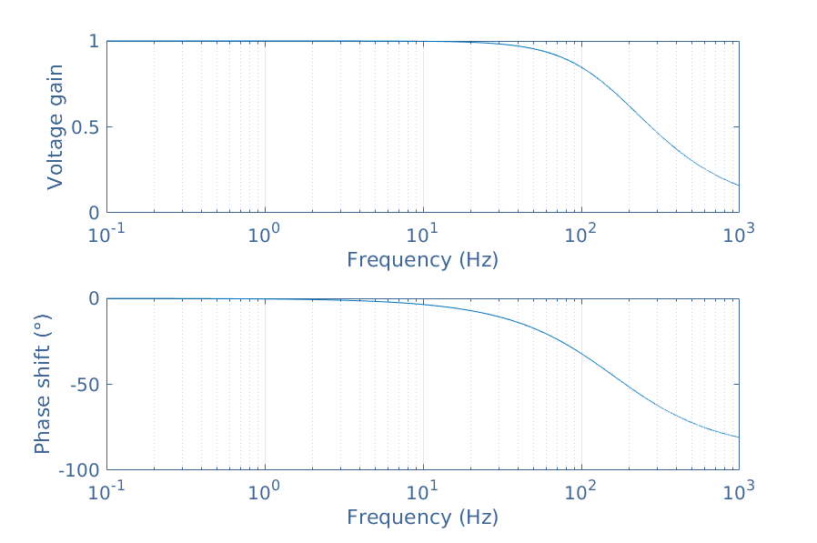
We can plot these two quantities on a Bode diagram by choosing for example R=100 Ω and C=1 μF :
fig 6 : Bode diagram of the RC series circuit
From the Bode diagram, we can observe that the RC series circuit is a low-pass filter since at low frequencies, the gain is equal to 1 and when the frequency increases, the gain tends to 0.
LC filters
The association of an inductor with a capacitor is more interesting because a completely opposite behavior appears when connected in series or parallel, which isn’t the case for the RC filter.
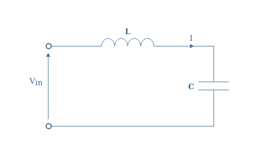
Let’s first of all consider the series circuit such as represented in Figure 7 :
fig 7 : LC series circuit
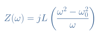
The total impedance Z is given by Z=ZC+ZL=jLω+(1/jCω). We can rewrite this expression with a common denominator, and by defining the quantity ω0=1/√(LC), it comes :
eq 8 : Impedance of a LC series circuit
We can see that Z(ω0)=0, for this reason, ω0 is named the resonance frequency. When connected with a load, an LC circuit will behave as a band-pass filter around ω0.
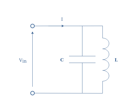
The parallel circuit represented in Figure 8 behaves exactly at the opposite of the series circuit.
fig 8 : LC parallel circuit
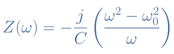
With the same method as exposed previously, the total impedance can be written such as :
eq 9 : Impedance of a LC parallel circuit
Here however, Z(ω0)→+∞ which means that at the resonant frequency, the circuit behaves as an open circuit. When connected with a load, the LC parallel filter act as a band-stop filter around ω0.
Conclusion
We have first presented the concept of capacitance in order to understand better how capacitors works. The capacitance reflects the opposition of current that a component creates due to a change of voltage. We have seen that in DC regime, a capacitor just stores energy in the form of charges with no current being observed. The charges can however be released if a change of voltage happens : this is the case in AC regime.
By describing the capacitive reactance, we have seen that the opposition to the current of a capacitor depends inversely with the frequency. In DC regime, the capacitor is an open circuit and as the frequency increases, it becomes a short circuit.
Finally, the association of resistors and inductors with capacitors can create interesting filters. The RC series circuit is a low-pass filter : it attenuates high frequencies. The LC series circuit is a band-pass filter : it attenuates the frequencies out of a certain band around the resonance frequency. The LC parallel circuit is a band-stop filter : it attenuates the frequencies within a certain band around the resonance frequency.
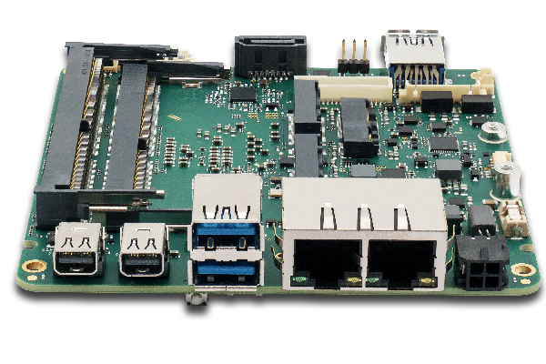
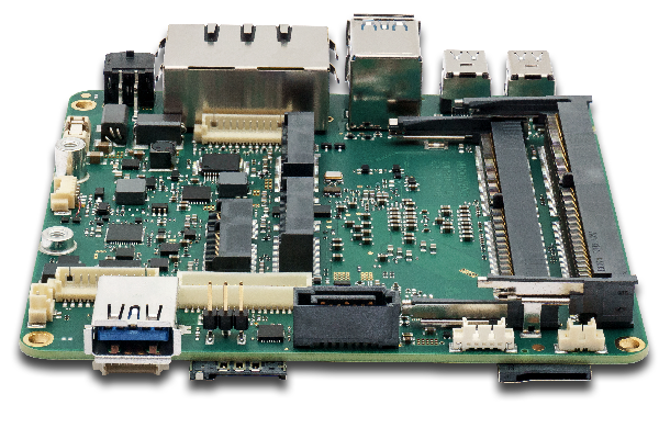
Interest in SBCs is growing and even though their capabilities have improved over the years, there is a yearning for more, from processing power to IOs. To add to their already impressive line of SBC offerings, EEPD (Electronic Equipment Production and Distribution) recently announced the release of two SBCs; the Profive NUCV and the Profive NUCR which are based on the AMD Ryzen Embedded V1000 and R1000 respectively.
PROFIVE® Single Board Computer NUCR (x86)
The boards were both designed for industrial applications with EEPD mentioning that the boards were targetted at applications across various sectors including; aerospace and defense, industrial control and automation, IoT, Networking and thin clients, Medical Imaging, digital casino gaming, along with digital signage and retail to mention a few.
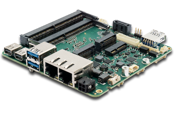
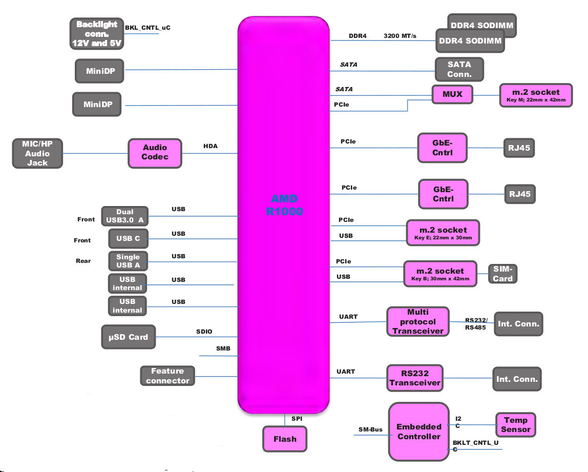
In line with the NUC standard, the boards utilize the AMD Ryzen Embedded platform with a Radeon Vega Graphics card integrated into the system. While the boards have a lot of similarity in face value, quite a number of differences exist within them. For instance, the NUCV comes with 4 different variants offering 4 different Ryzen Embedded V1000 series CPU and Vega 3, 8 and 11 AMD Radeon Graphics to choose from, while the NUCR, on the other hand, only has two variants of the R1000 series CPU with just the AMD Radeon Vega 3 graphics option. Both boards support operating systems like Windows 10, the Windows 10 IoT Enterprise and Linux ubuntu among others. A summary of the features of these two board categories is provided below;
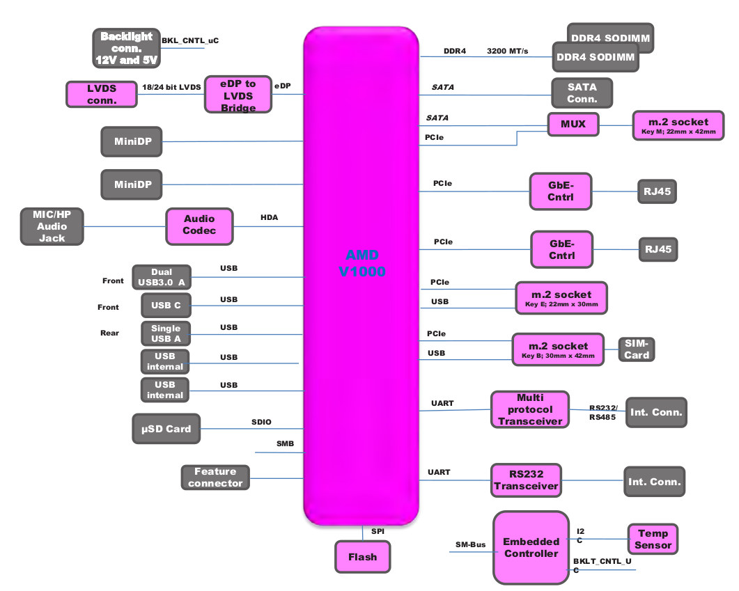
PROFIVE® Single Board Computer NUCV (x86)
SBC Profive NUCV Specifications
AMD processors of the V1000 series – V1202B / V1605B / V1756B / V1807B up to 35W TDP (max TDP supported by the board)
Supported operating systems: Microsoft Windows 10 / 10 IoT Enterprise, Linux Ubuntu 18.04 LTS
A Block Diagram for the Profive NUCv SBC
The two boards seem to be currently available in different processors and memory configurations, but the information provided on their respective product pages does not include their price details. This may be a result of the different configurations available and can however be ratified by speaking to the company’s representatives. More information about the features and capabilities of the Profive NUCr and NUCv boards can be found on their individual product pages (Hotlinked).
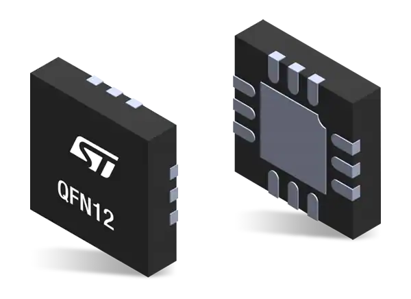
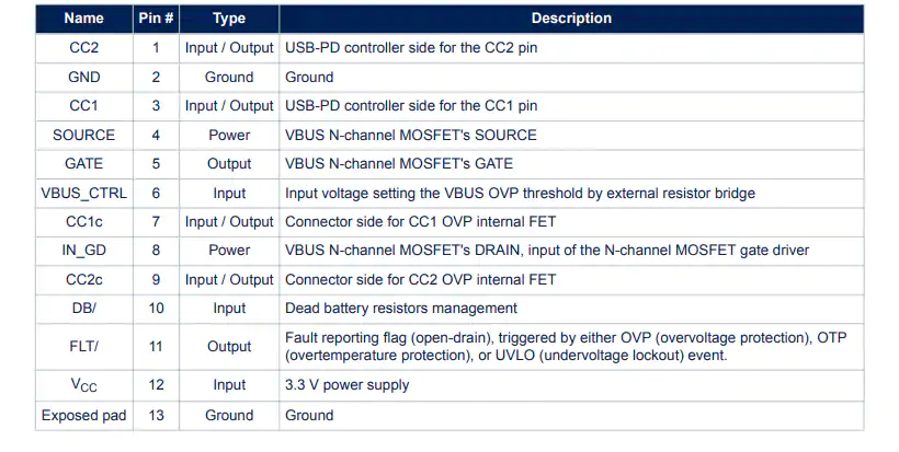
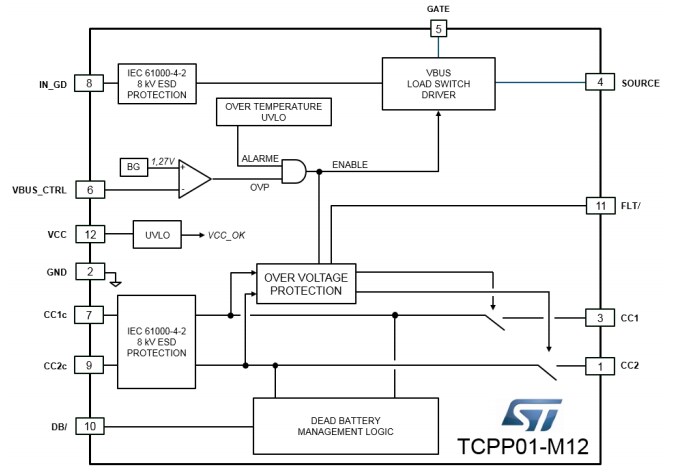
STMicroelectronicsTCPP01-M12 USB Type-C Port Protection is a single-chip solution that facilitates the migration from USB legacy connectors type-A or type-B to USB Type-C connectors. This Type-C port protection features overvoltage protection on VBUS, adjustable up to 22 V, with external N-channel MOSFET. The TCPP01-M12 USB port protection includes an integrated charge pump to control the gate of an external N-channel MOSFET. This Type-C port protection offers Over Temperature Protection (OTP), open-drain fault reporting, and integrated dead battery.
The TCPP01-M12 USB port protection operates at -40°C to 85°C junction temperature range. This Type-C port protection function with 6V overvoltage protection, 150°C junction-to-ambient thermal resistance, and 122μA supply current. The TCPP01-M12 USB Type-C port protection is ideal for use in sink configuration, source configuration, UFP or DFP configuratioN, power delivery, and PPS compliant.
Features
Overvoltage protection on VBUS with external N-channel MOSFET
System-level ESD protection for USB type-C connector pins
Compliant with IEC 61000-4-2 level 4
Integrated charge pump to control the gate of an external N-channel MOSFET
Null quiescent current when no USB charging cable is attached for battery operated “consumer/sink” applications
Integrated “dead battery” (RD resistors)
Over-temperature protection
Complies with the latest USB Type-C and USB power delivery standards
Compliant with Programmable Power Supply (PPS) as defined in the latest USB PD specification
Open-drain fault reporting
ECOPACK2 compliant
Specifications
6V overvoltage protection
At Absolute maximum ratings (Tamb = 25°C):
-40°C to 85°C operating junction temperature range
-55°C to 150°C storage temperature range
150°C/W junction-to-ambient thermal resistance
At Power supply and leakage current, Tamb = -40 °C to 85 °C:
3V to 3.6V input voltage range
120μA supply current
Applications
USB Type-C for UFP (upstream facing port) or DFP (downstream facing port) configuration
USB Type-C power delivery, PPS compliant
USB Type-C used in sink configuration (consumer)
USB Type-C used in source configuration (provider)
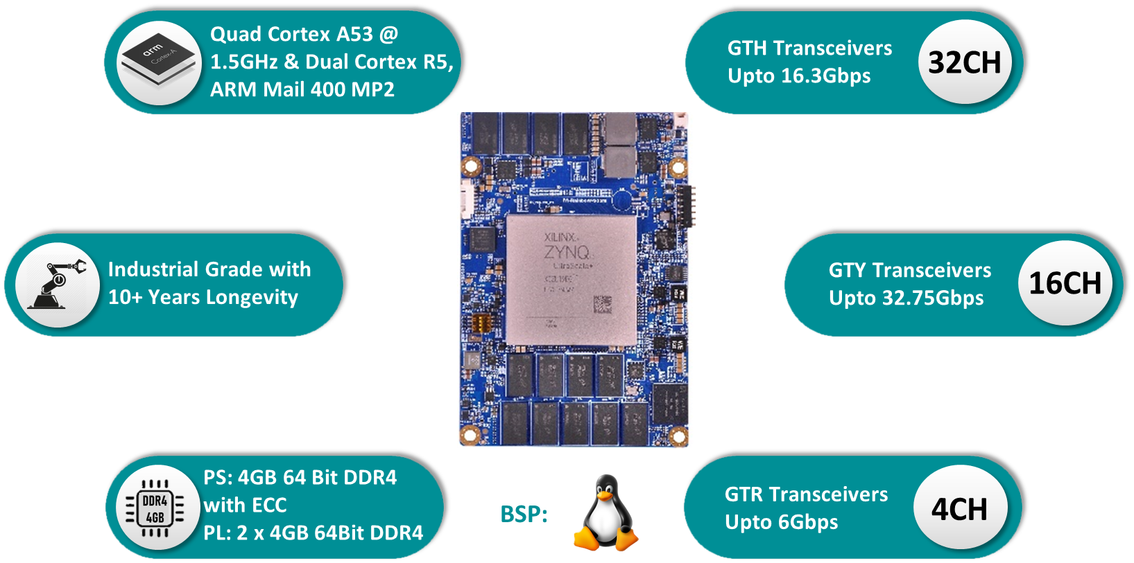
iWave Systems introduces a powerful SOM (System on Module) with six heterogeneous ARM processor cores (four 64-bit ARM Cortex-A53 and two 32-bit ARM Cortex-R5 Cores), an ARM Mali-400 MP2 GPU, and a big chunk of the latest-generation UltraScale+ programmable logic cells scaling all the way to 1 million. Designed a ZU19EG / ZU17EG / ZU11EG Zynq UltraScale+ MPSoC System on Module in the package C1760 and a 10+ Years Longevity support.
The CPU module has a compact-size measuring 110mm by 75mm, equipped with ZU19/17/11 EG MPSoC, 64-Bit 4GB DDR4 for PS, dual 4GB DDR4 64-Bit for PL, 8GB eMMC (expandable up to 128GB) as well as integrated with Ethernet PHY, USB PHY, and power circuitry to provide control and processing capabilities as an embedded system. Besides these, all the FPGA IOs, 16 x PL-GTY @32.75Gbps, 32 x PL-GTH @16.3Gbps, 4 x PS-GTR @6Gbps Transceivers & FPGA IOs up to 48LVDS/96SE + 46SE IOs are terminated at high-speed Board-to-Board (B2B) connector.
Product Highlights:
It is ready to run Linux OS and targets a wide variety of applications like the High-Speed Networking using 25G, 40G & 100G Optical, Cloud Computing, 4K Video Surveillance System, Deep Neural AI/ML Networks, Automotive Imaging Radar, Intelligent Data Center, etc.,
Targeted Applications
iWave Systems has the stock of various ZU19EG / ZU17EG / ZU11EG MPSoC based SOMs which is ready for immediate dispatch
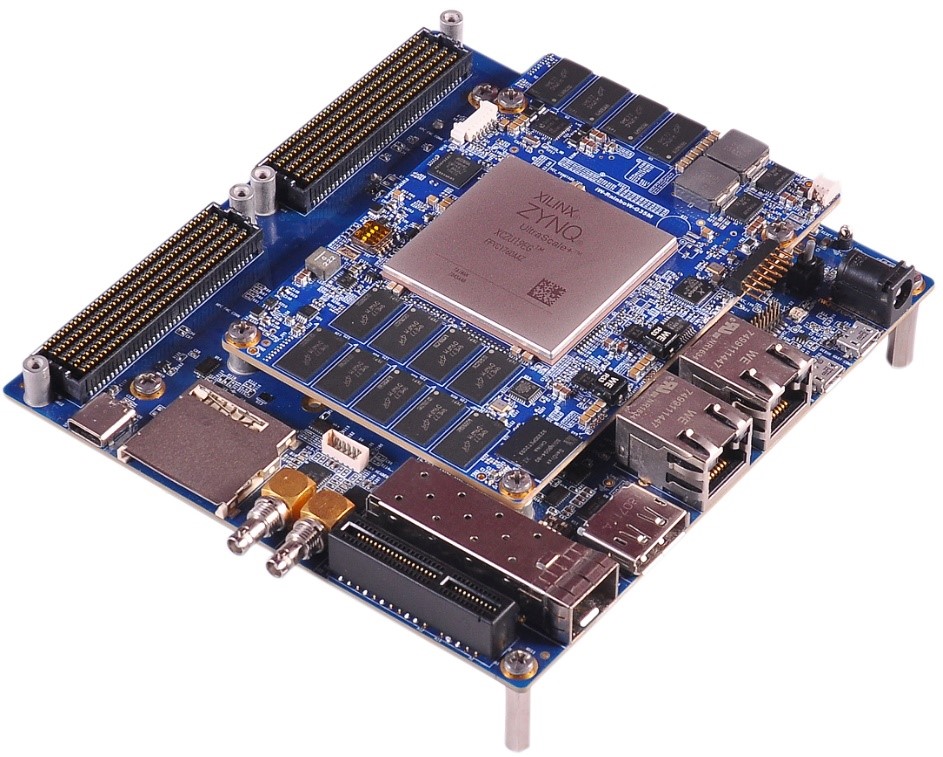
iWave Systems also offers a versatile iW-RainboW-G35D Development Board for evaluating the SOM Module. It takes full features of the Zynq UltraScale+ MPSoC device to have explored a robust set of peripherals such as Dual FMC for doing initial POC with the available off-the-shelf FMC boards, 12G SDI IN & OUT, SFP+, USB 3.0 Type C, Gigabit Ethernet, Dual PMOD, DisplayPort (DP), PCIe x4 interface, M.2 SATA interface, JTAG, CAN and so on. The iW-RainboW-G35D is a solid reference design for development based on Xilinx Zynq UltraScale+ MPSoC solutions.
More information about the new products can be found at:
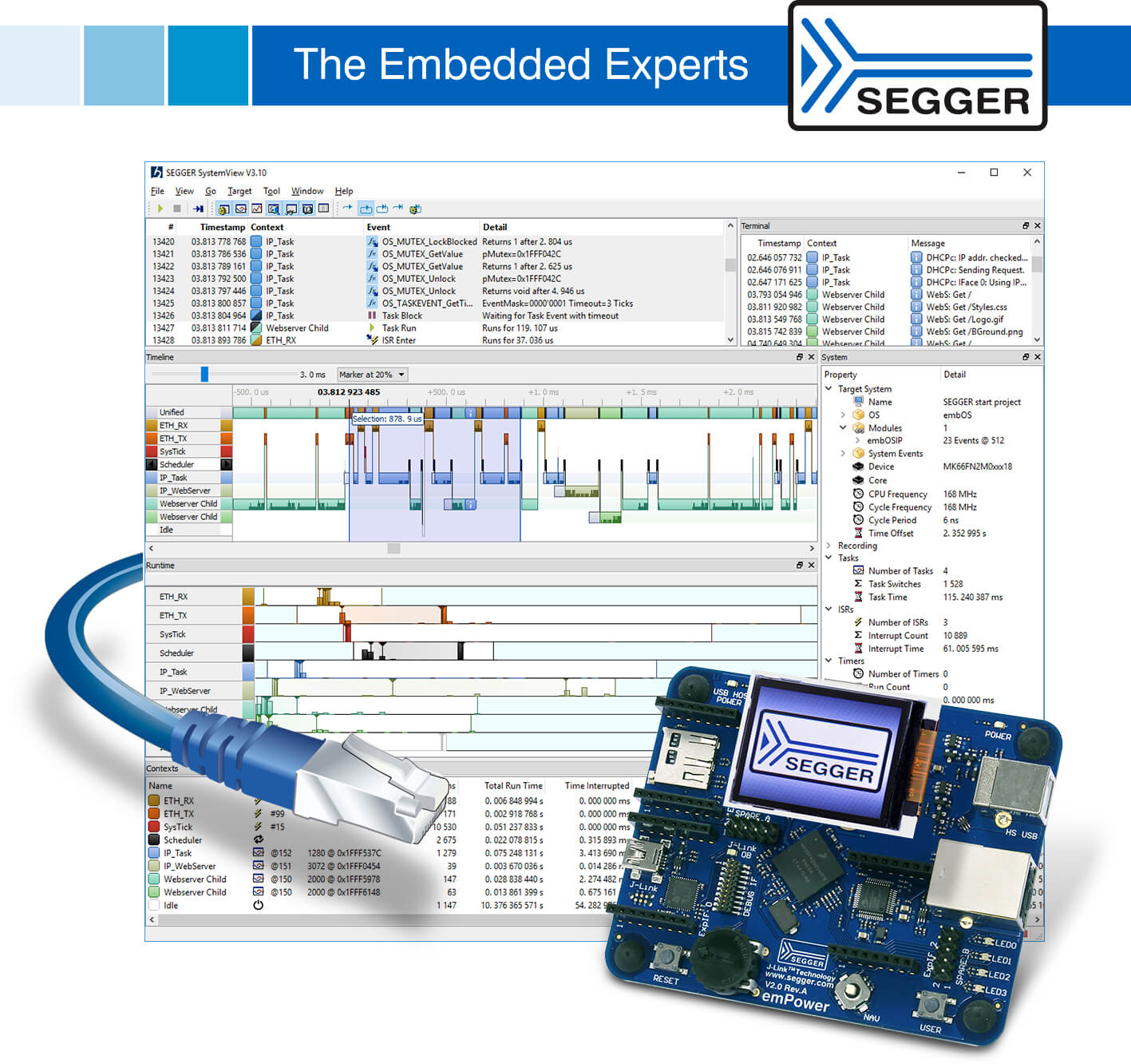
SEGGER announces the release of SystemView V3.10, a major update to its system verification tool for embedded systems. The most significant enhancement is the addition of real-time data acquisition via UART or TCP/IP. Any system with UART or TCP/IP connection, typically Ethernet, can now be monitored and verified.
The new version comes with the target code required for integration as well as example projects.
The software also adds a variety of new features. New performance markers are useful for performance verification and optimization. A new Runtime window provides information on the runtime distribution of tasks, interrupts and software timers. All windows are updated in real-time, with no limit on the sampling time due to streaming data acquisition. The entire data set can be stored for later or remote analysis as well as archival and documentation purposes. SystemView also comes with the files required for many popular RTOS such as embOS, FreeRTOS, uC/OS-II and uC/OS-III, and more. Any system, with or without RTOS, can be monitored.
SystemView V3.10 can be easily downloaded and installed without any registration process. It is available under SEGGER’s friendly licensing policy, and –like SEGGER’s Ozone debugger and SEGGER’s Embedded Studio IDE – is free for non-commercial purposes as well as unlimited evaluation, even for the commercial user. Previous releases of the software continue to be available on segger.com.
SystemView, like Ozone and Embedded Studio, works cross-platform for Windows, macOS, and Linux.