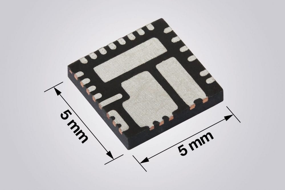
Vishay Intertechnology, Inc. has introduced two new families of 2A to 12A microBUCK® synchronous buck regulators featuring wide input voltage ranges from 4.5V to 55V (SiC476/7/8/9) and 4.5V to 60V (SiC466/7/8/9). Combining rugged high-performance n-channel trench MOSFETs with a controller in the compact 5×5 PowerPAK® package, the Vishay Siliconix devices deliver high efficiency and power density, while their internal compensation reduces the external component count.
The microBUCK regulators announced today share the same controller IC and package outline while providing a range of MOSFET ratings from which designers can select the best combination of cost and performance.
Offering a low 156µA operating current and peak efficiency up to 98%, the regulators released today allow designers to increase power density by reducing power losses. Combined with the superior thermal design of the 5mm x 5mm PowerPAK package, their efficiency enables cooler operation for improved long-term reliability while eliminating the need for a heatsink.
The microBUCK wide safe operating area gives designers flexibility to support a wide range of operating temperature and current requirements. This allows designers to shrink the PCB size, simplify thermal management, and reduce system costs.
With their input voltage ranges and an adjustable output voltage from 24V down to 0.8V, SiC466/7/8/9 and SiC476/7/8/9 family regulators are designed for a wide range of applications. These include dc-dc converters for industrial and factory automation, home automation, industrial computing, base station power supplies, 5G network equipment and small cells, wall transformer regulation, robotics, drones, battery management systems, power tools, and vending, ATM, and slot machines.
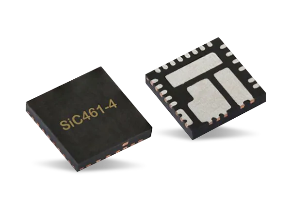
The new SiC46x family devices are the 2A SiC469, 4A SiC468, 6A SiC467, and 10A SiC466, while the new SiC47x family devices are the 3A SiC479, 5A SiC478, 8A SiC477, and 12A SiC476. All are footprint-compatible to provide a scalable solution to designers.
Highly configurable, the regulators feature adjustable switching frequencies from 100 kHz to 2 MHz, adjustable soft start and current limits, and two operating modes: forced continuous conduction or power save. The internal compensation in both families eliminates the need for external RC networks.
The microBUCK COT architecture delivers ultrafast transient response with minimum output capacitance and tight ripple regulation at light loads. It also enables loop stability regardless of the type of output capacitor used, including low ESR ceramic capacitors.
The regulators integrate a robust protection feature set, including output overvoltage protection, output undervoltage protection, overcurrent circuit protection, short circuit protection with auto retry, over temperature protection, and a power good flag.
Samples and production quantities of the SiC466/7/8/9 and SiC476/7/8/9 families are available now, with lead times of 12 weeks. Pricing for U.S. delivery only starts at $1.80 per piece in 1000-piece quantities.
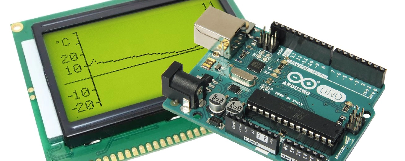
Using the tiny Arduino Uno, you can build all manner of really neat small projects at modest cost. This one is a simple temperature recorder that shows on a display screen the values measured during the past 24 hours. Of particular note is the software, which manages all of the operations without recourse to external libraries.
The recorder described in this article measures the temperature over the course of a day and displays the readings on a graphic display screen. When a new measured value is added, the displayed curve is shifted one pixel to the left, so that the oldest value disappears and the newest reading appears. The interval between measurements can be changed easily to record more rapid temperature changes, for example in process control applications.
The project software, with comments, can be downloaded by clicking on DOWNLOAD ATTACHMENT below.
Over time we have built quite a number of data logger projects, but the emergence of more modern development boards, sensors and platforms mean there is an opportunity to add several new features to data-logging devices. For today’s tutorial, we are going to build a datalogger based on one of Arduino’s recent boards; the Nano 33 Sense IoT board.
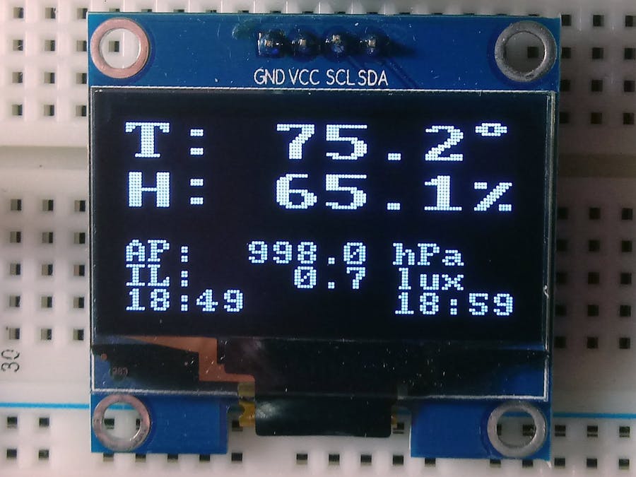
YADL Display
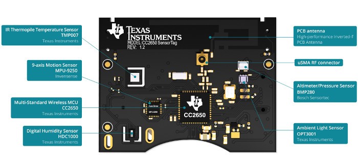
The project basically involves the logging of temperature, pressure, humidity, and light intensity data collected from the Texas Instrument’s sensorTag to an SD Card with the Nano 33 IoT board in between. The TI SensorTag packs many different sensors into a small battery-powered unit and uses Bluetooth Low Energy (BLE) to communicate readings to connected devices like mobile phones, tablets or microcontrollers. It belongs to a new class of sensors that are developed to reduce power consumption, improve portability and eradicate compatibility issues between sensors and microcontrollers. Sensors like the SensorTag are self-contained and possess all they need to exist alone, collecting data and just streaming to whoever calls over BLE. Other communication protocols used by such sensors include BLE, Zigbee, LoRa, and even WiFi.
The Nano 33 IoT Board comes with onboard wireless features like WiFi and Bluetooth BLE along with an onboard RTC all of which makes it the perfect data-gathering device. The presence of the onboard BLE and the ability of the sensorTag to communicate its data over BLE means we can easily query the SensorTag for the data we require and it will automatically be sent over WiFi. The data received can then be logged on the SD Card.
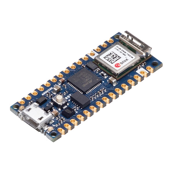
Nano 33 IoT
At the end of today’s tutorial, you would know how to work with the Nano 33 IoT board and also use the TI Sensor Tag.
Required Components
The following components are required to build today’s project;
For our own build, we will use the Nano 33 sense IoT board, but since it is compatible with the MKR WiFi 1010, on the level at which we will be using it, you can choose to work with the MKR as well.
The exact version of these components used for this tutorial can be bought from the links attached to them.
Schematics
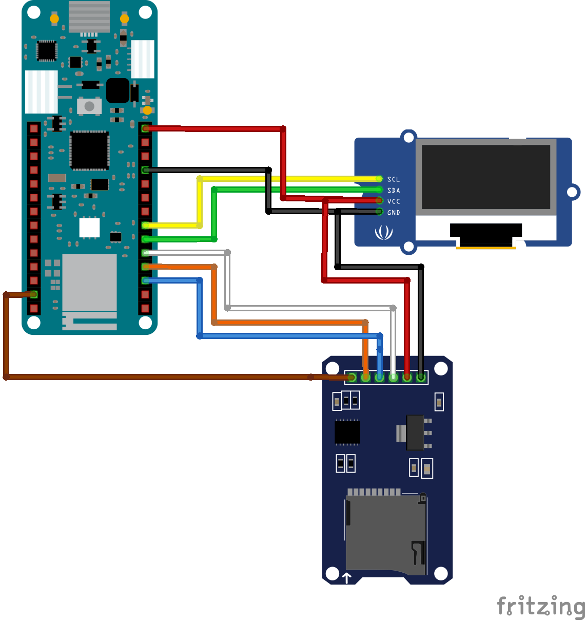
The schematics for this project is quite straight forward. We will connect the SD Card module to the Nano 33 IoT Board via its SPI pins while the OLED display will be connected over I2C. The sensor tag is self-contained and communicates with the microcontroller via Bluetooth as such there will be no physical connection between it and the Nano 33 IoT board.
The schematic showing how the components are connected is provided in the image below:
Schematics
To make the schematics easier to follow, a pin-pin description of the connection between the components is provided below.
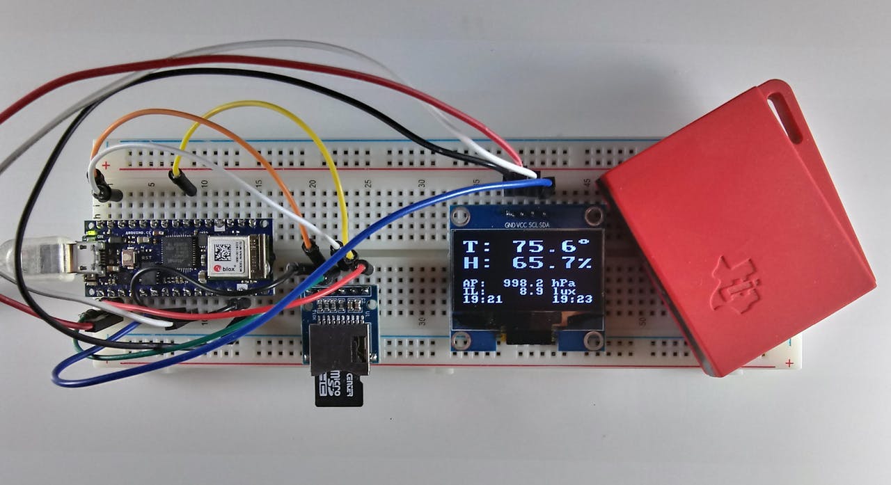
Go over the connections again to ensure everything is as it should be before proceeding to the next section. The setup with everything properly connected should look like the image below.
Code
Based on the goals of the project described under the introduction section, the code for this project is required to query the sensor tag to measure the temperature in Fahrenheit, Relative humidity, barometric pressure, and illumination level of the environment. All of these data are then logged (optional) on the SD Card and displayed on the OLED.
To reduce the amount of work involved, and help optimize the code, we will use Arduino libraries like; the WiFiNINA v1.40 library, the ArduinoBLE library (v1.1.1), RTCZero library (1.6.0), the SD library (v1.2.3), and the U8g2 library. All the libraries can either be installed via the Arduino IDE or downloaded from the links attached to them. The versions of the libraries are added so you can get their exact version as some of them have backward compatibility issues so getting an older or newer version of that same library might not work.
The WiFiNINA library is used to perform all the WiFi related tasks associated with the project while the ArduinoBLE Library facilitates interaction with the SensorTag. The RTCZero library helps with tracking time so the data stored can be timestamped while the SD library facilitates logging the data and the U8G2 library handles the display of that data on the OLED.
With all the libraries installed, we can now proceed to write the code for the project.
As usual, I will do a quick run through the code to explain parts of it that could be difficult.
We start the code by including all the required libraries. These are the same libraries discussed above.
include <WiFiNINA.h>
#include <RTCZero.h>
#include <ArduinoBLE.h>
#include <SPI.h>
#include <SD.h>
#include <U8x8lib.h>
#include <avr/dtostrf.h> // needed for MKR1010
Next, we create an instance of some of the libraries to be used to reference them in our code.
Next, we create a global structure to hold the data obtained from the SensorTag.
// Global structure to hold the sensor data
struct DATA {
  float tem;     // HDC1000 temperature F
  float hum;     // HDC1000 relative humidity %RH
  float bptemp;  // BMP 280 die temperature F
  float bp;      // BMP 280 barometric pressure in hectoPascals (1 hPa = 100 Pa)
  float li;      // OPT3001 lux
  float temd;    // TMP007 die temperature F
  float temo;    // TMP007 object temperature F
};
We also create a bunch of other variables all of which are properly commented with the purpose which they serve properly stated.
// lcd vars
char degree[] = {0xb0, 0x00};
char percent[] = {0x25, 0x00};
char p_buffer[12] = {0, 0, 0, 0, 0, 0, 0, 0, 0, 0, 0, 0};

// clock change catcher
int lastmin;

// for RTC
unsigned long epoch;
int numberOfTries = 0, maxTries = 6;

int status = WL_IDLE_STATUS;  // WiFiNINA use

// Common user-changeable switches
const int GMT = -4; //change this to adapt it to your time zone
byte SDswitch = 1;  // SDswitch 1=ON (write to SD) or 0 (Do not write to SD)
char fname[] = "STDATA.txt"; // data log file Name

//period defines the length of time between measurements in milliseconds
// note that this does not includes delays for sensor reads (~8.7 sec)
long period = 600000L; // 10 minutes
//long period = 5000L;  // 5 sec for testing
Next, we specify the credentials (SSID and Password) of your WiFi access point through which the device is able to connect to the internet. Provide the Key Index if the WiFi security is WEP.
char ssid[] = "";   // your network SSID (name)
char pass[] = "";   // your network password (use for WPA, or use as key for WEP)
int keyIndex = 0;             // your network key Index number (needed only for WEP)
Next, we create SensorTag Characteristics definition to help us pull data from specific sensors. The description for each of the characteristic definitions can be found in sensorTag’s datasheet. You can go through it to know what to call to get data from a particular sensor.
With this done, we are now ready to write the void setup() function.
We start the function by initializing the OLED via the U82g library, setting the font with which text is displayed and displaying a string “YADL Starting..” to serve as a splash screen.
Next, we initialize serial communication to provide an avenue for debugging via the serial monitor. The code is delayed for a few seconds after every restart to allow the user to launch the serial monitor before data display commences.
#ifdef DEBUG
  Serial.begin(9600);
  delay(5000);  // delay for user to open the serial monitor
  Serial.println("YADL MKR1010/NANO IOT 33 SensorTag Data Logger");
  Serial.println();
#endif
The use of the SD Card is optional so next, we write the code to check/state the users preferred option. If you do not want to use an SD card to save the data, you can eliminate that function by setting the value of the SDswitch variable to “0” but by default, the option to write to the SD is on(“1”). If the option is 1, then the code checks to confirm that an SD card is inserted and working. If not, an error (“No SD Card”) will be displayed and execution goes no further, but if the Card is present and functional, the system continues its operation.
 // check the SD card
  if (SDswitch == 1) {
    if (!SD.begin(4)) {
      u8x8.drawString(0, 2 , "No SD card!");
      u8x8.drawString(0, 3 , "Terminal Error!");
#ifdef DEBUG
      Serial.println("SD Card initialization failed!");
#endif
      while (1);
    }
    else {
      u8x8.drawString(0, 2 , "SD card found. ");
      delay(2000);    // to let user know
      u8x8.drawString(0, 2 , "               ");
#ifdef DEBUG
      Serial.println("SD Card found");
#endif
    }
  }
  else {
    u8x8.drawString(0, 2 , "No SD card");
    u8x8.drawString(0, 3 , "option");
    delay(2000);    // to let user know
    u8x8.drawString(0, 2 , "          ");
    u8x8.drawString(0, 3 , "      ");
#ifdef DEBUG
    Serial.println("No SD Card option");
#endif
  }
Next, we confirm the active status of the onboard WIFi module and if available we connect to the access point using the credentials provided earlier. The connection status is displayed and the board’s WiFi capability is used to contact a time server to get the current epoch. Note that you can correct this epoch for your time zone and DST setting (see program variable GMT). Once the epoch is obtained, the onboard real-time-clock (RTC) is set and used to keep the time.
  // check if the WiFi module works
  if (WiFi.status() == WL_NO_SHIELD) {
#ifdef DEBUG
    Serial.println("WiFi shield not present");
#endif
    u8x8.drawString(0, 1 , "NO WiFi!");
    u8x8.drawString(0, 2 , "Terminal Error!");
    // don't continue:
    while (true);
  }

  // attempt to connect to WiFi network:
  u8x8.drawString(0, 2 , "Connecting.....");
  while ( status != WL_CONNECTED) {
#ifdef DEBUG
    Serial.print("Attempting to connect to SSID: ");
    Serial.println(ssid);
#endif
    // Connect to WPA/WPA2 network. Change this line if using open or WEP network:
    status = WiFi.begin(ssid, pass);
    delay(10000); // wait 10 seconds for connection:
  }
  u8x8.drawString(0, 3 , "Connected!     ");
#ifdef DEBUG
  printWiFiStatus(); // you're connected now, so print out the status:
#endif
  rtc.begin();
  do {
    epoch = WiFi.getTime();
    numberOfTries++;
  }
  while ((epoch == 0) && (numberOfTries < maxTries));

  if (numberOfTries == maxTries) {
    u8x8.drawString(0, 4 , "NTP Unreachable");
    u8x8.drawString(0, 5 , "TERMINAL ERROR!");
#ifdef DEBUG
    Serial.print("NTP unreachable!!");
#endif
    while (1);
  }
  else {
    u8x8.drawString(0, 4 , "Got NTP Epoch  ");
    epoch = epoch + (GMT * 3600UL); // adjust offset for TZ/DST
    rtc.setEpoch(epoch);
#ifdef DEBUG
    Serial.print("Epoch received: ");
    Serial.print(epoch);
    Serial.print(" ");
    printP02D(rtc.getHours());
    Serial.print(":");
    printP02D(rtc.getMinutes());
    Serial.print(":");
    printP02D(rtc.getSeconds());
    Serial.print(" ");
    Serial.print(rtc.getDay());
    Serial.print("/");
    Serial.print(rtc.getMonth());
    Serial.print("/");
    Serial.print(rtc.getYear());
    Serial.println();
#endif
After the time epoch has been received and the RTC corrected, WiFi is ended and BLE begins. Since both of the boards have WiFi and BLE capability, this is easily accomplished.
    WiFi.end();
    delay(15000);
    u8x8.drawString(0, 5 , "WiFi Ended     ");
    u8x8.drawString(0, 6 , "Starting BLE   ");
    delay(2000); // to see it on the screen
#ifdef DEBUG
    Serial.println("WiFi.end executed");
#endif
  }
  // Try to initialize BLE
  if (!BLE.begin()) {
    Serial.println("Terminal Error: Could not start BLE!");
    u8x8.clear();
    u8x8.drawString(0, 0 , "BLE Start Fail");
    u8x8.drawString(0, 1 , "Terminal Error!");
    while (1);
  }
Finally, for the void setup(), the BLE is put into scan mode and the user is notified of the mode via the OLED display.
Next, we move to the void loop() function. We start the function by running scans to see if a Bluetooth device is available. If it is, then we check if it is the SensorTag and we attempt to connect when it is found.
void loop() {
  long lastMillis = 0;  // for period test
  long nowMillis = 0;   // for period test

  // check if a peripheral has been discovered
  peripheral = BLE.available();
  if (peripheral) {
    // discovered a peripheral, print out address and local name
#ifdef DEBUG
    Serial.print("Found ");
    Serial.print(peripheral.address());
    Serial.print(" '");
    Serial.print(peripheral.localName());
    Serial.println("' ");
#endif
    if (peripheral.localName() == "CC2650 SensorTag") {
      BLE.stopScan(); // stop scanning
      // connect to the peripheral
      u8x8.drawString(0, 1 , "Connecting....");
#ifdef DEBUG
      Serial.print("Connecting to SensorTag ...");
#endif
      if (peripheral.connect()) {
        u8x8.drawString(0, 2 , "Connected.....");
#ifdef DEBUG
        Serial.println("Connected...");
#endif
With the SensorTag now connected, we proceed to read the various sensors and write the data to the SD Card using the Write_SDdata function.
while (peripheral.connected()) {
    read_BP(peripheral);
    read_OPT(peripheral);
    read_IRT(peripheral);
    read_HUM(peripheral);
    if (SDswitch) write_SDdata(); // write data to sd card
    // screen for debug no print here as well
At this point, it is important to note that there are different versions of the SensorTag CC2650 and some newer versions may not include the TMP007 sensor like the one used for this project. If that is the case, all you need do is comment out the program references to that unavailable sensor.
With the data logged on the SD, it is then displayed on the OLED and also on the serial monitor.
#ifdef DEBUG
      print_data();
#endif
      print_screenValues();
      printclockD(1); // Update sensor clock
      printclockD(2); // update current clock
      lastmin = rtc.getMinutes();
      lastMillis = millis();
      // stay here until the period is up
      // update current time here
      while ( ( (nowMillis = millis()) - lastMillis) <= period) {
        // need to update the clock here
        if (lastmin != rtc.getMinutes()) {
          lastmin = rtc.getMinutes();
          printclockD(2); // update current clock
        }
      }
    }
The buffer is cleared and the scan process is repeated.
The remaining part of the sketch represents the code snippets for the functions that were called within the setup() and loop() functions.
// BLE SensorTag routines
void do_discovery(BLEDevice peripheral) {
  // discover the peripheral's attributes that we want
  // barometric
#ifdef DEBUG
  Serial.print("Discovering attributes for Barometric Pressure service ...");
#endif
  if (peripheral.discoverService("f000aa40-0451-4000-b000-000000000000")) {
#ifdef DEBUG
    Serial.println("discovered");
#endif
    BPConCharacteristic = peripheral.characteristic("f000aa42-0451-4000-b000-000000000000");
    BPValCharacteristic = peripheral.characteristic("f000aa41-0451-4000-b000-000000000000");
  }
  else  {
#ifdef DEBUG
    Serial.println("ERROR: Barometric Pressure service discovery failed.");
#endif
    peripheral.disconnect();
    return;
  }
  // discover the peripheral's attributes that we want
  // optical sensor
#ifdef DEBUG
  Serial.print("Discovering attributes for Luxometer service ...");
#endif
  if (peripheral.discoverService("f000aa70-0451-4000-b000-000000000000")) {
#ifdef DEBUG
    Serial.println("discovered");
#endif
    OPTConCharacteristic = peripheral.characteristic("f000aa72-0451-4000-b000-000000000000");
    OPTValCharacteristic = peripheral.characteristic("f000aa71-0451-4000-b000-000000000000");
  }
  else  {
#ifdef DEBUG
    Serial.println("Error: Luxometer service discovery failed.");
#endif
    peripheral.disconnect();
    return;
  }
  // IR
#ifdef DEBUG
  Serial.print("Discovering attributes for Infrared service ...");
#endif
  if (peripheral.discoverService("f000aa00-0451-4000-b000-000000000000")) {
#ifdef DEBUG
    Serial.println("discovered");
#endif
    IRTConCharacteristic = peripheral.characteristic("f000aa02-0451-4000-b000-000000000000");
    IRTValCharacteristic = peripheral.characteristic("f000aa01-0451-4000-b000-000000000000");
  }
  else  {
#ifdef DEBUG
    Serial.println("Error: Infrared service discovery failed.");
#endif
    peripheral.disconnect();
    return;
  }
  // humidity
#ifdef DEBUG
  Serial.print("Discovering attributes for Humidity service ...");
#endif
  if (peripheral.discoverService("f000aa20-0451-4000-b000-000000000000")) {
#ifdef DEBUG
    Serial.println("discovered");
#endif
    HUMConCharacteristic = peripheral.characteristic("f000aa22-0451-4000-b000-000000000000");
    HUMValCharacteristic = peripheral.characteristic("f000aa21-0451-4000-b000-000000000000");
  }
  else  {
#ifdef DEBUG
    Serial.println("Error: Humidity service discovery failed.");
#endif
    peripheral.disconnect();
    return;
  }
}

// Sensor reads
void read_BP(BLEDevice peripheral) {
  uint8_t holdvalues[6];

  if (peripheral.connected()) {
    // wake up the sensor
    BPConCharacteristic.writeValue(sensorOn);
    delay(1200); // wait for the sensor to do a read
    BPValCharacteristic.readValue(holdvalues, 6);
    unsigned long rawbptemp = (holdvalues[2] * 65536) + (holdvalues[1] * 256) + holdvalues[0];
    unsigned int rawbp = (holdvalues[5] * 65536) + (holdvalues[4] * 256) + holdvalues[3];
    // sleep sensor
    BPConCharacteristic.writeValue(sensorOff);
    // calculate temperature and pressure final values
    float bptemp = ((double)rawbptemp / 100.0);
    bptemp = ((bptemp * 9.0) / 5.0) + 32.0; // convert to F - comment out to leave at C
    float bp = ((double)rawbp / 100.0);
    // save into the structure
    SensorData.bp = bp;
    SensorData.bptemp = bptemp;
  }
  else {
#ifdef DEBUG
    Serial.println(" *not connected* ");
#endif
  }
}

void read_OPT(BLEDevice peripheral) {
  // in this version the characteristic's value is read directly
  // into rawlux and then processed. No array is used.

  uint16_t rawlux;

  if (peripheral.connected()) {
    // wake up the sensor
    OPTConCharacteristic.writeValue(sensorOn);
    delay(1200); // wait for the sensor to do a read
    OPTValCharacteristic.readValue(rawlux);
    OPTConCharacteristic.writeValue(sensorOff); // sleep sensor
    // calculate lux final value
    unsigned int m = rawlux & 0x0FFF;
    unsigned int e = (rawlux & 0xF000) >> 12;
    float lux = (m * (0.01 * pow(2.0, e)));
    // save into the structure
    SensorData.li = lux;
  }
  else {
#ifdef DEBUG
    Serial.println(" *not connected* ");
#endif
  }
}

void read_IRT(BLEDevice peripheral) {
  uint8_t holdvalues[4];

  if (peripheral.connected()) {
    // wake up the sensor
    IRTConCharacteristic.writeValue((uint8_t) 0x01);
    delay(1200); // wait for the sensor to do a read
    IRTValCharacteristic.readValue(holdvalues, 4);
    unsigned int rawobj = (holdvalues[0]) + (holdvalues[1] * 256);
    unsigned int rawamb = (holdvalues[2]) + (holdvalues[3] * 256);
    IRTConCharacteristic.writeValue(sensorOff); // sleep sensor
    // calculate final temperature values
    const float SCALE_LSB = 0.03125;
    int it = (int)( rawobj >> 2);
    float IRTo = ( (float)it) * SCALE_LSB;
    IRTo = ( (IRTo * 9.0) / 5.0 ) + 32.0; // convert to F - comment out to leave at C
    it = (int)(rawamb >> 2);
    float IRTa = (float)it * SCALE_LSB;
    IRTa = ( (IRTa * 9.0) / 5.0) + 32.0; // convert to F - comment out to leave at C
    // save into the structure
    SensorData.temd = IRTa;
    SensorData.temo = IRTo;
  }
  else {
#ifdef DEBUG
    Serial.println(" *not connected* ");
#endif
  }
}

void read_HUM(BLEDevice peripheral) {
  uint8_t holdvalues[4]; // hold the characteristic's bytes

  if (peripheral.connected()) {
    // wake up sensor
    HUMConCharacteristic.writeValue(sensorOn);
    delay(1200); // wait for the sensor to do a read
    HUMValCharacteristic.readValue(holdvalues, 4);
    HUMConCharacteristic.writeValue(sensorOff); // sleep sensor
    unsigned int rawtem = (holdvalues[0]) + (holdvalues[1] * 256);
    unsigned int rawhum = (holdvalues[2]) + (holdvalues[3] * 256);
    // calculate final temperature and relative humidity values
    float temp = (rawtem / 65536.0) * 165.0 - 40.0;
    temp = ((temp * 9.0) / 5.0) + 32.0; // convert to F - comment out to leave at C
    float hum = ((double)rawhum / 65536.0) * 100.0;
    // save into the structure
    SensorData.tem = temp;
    SensorData.hum = hum;
  }
  else {
#ifdef DEBUG
    Serial.println(" *not connected* ");
#endif
  }
}

// Print serial and screen and write SD routines
void print_data() {
  // Print the data to the serial moniter
  // NOTE: the time vars could be slightly different then the SD card
  // since they are two different routines but the Serial prints are
  // mainly for debugging

  String separator = ", ";
  // Data Line as follow (with comma separator):
  // epoch day, month, year, hours, minutes, seconds, HDC1000 temp, HDC1000 hum,
  // BMP280 pressure, BMP280 tem, OPT3001 light (lux), TMP007 temp, TMP0007 object temp
#ifdef DEBUG
  Serial.print(rtc.getEpoch());
  Serial.print(separator);
  Serial.print(rtc.getDay());
  Serial.print(separator);
  Serial.print(rtc.getMonth());
  Serial.print(separator);
  Serial.print(rtc.getYear());
  Serial.print(separator);
  printP02D(rtc.getHours());
  Serial.print(separator);
  printP02D(rtc.getMinutes());
  Serial.print(separator);
  printP02D(rtc.getSeconds());
  Serial.print(separator);
  Serial.print(SensorData.tem);
  Serial.print(separator);
  Serial.print(SensorData.hum);
  Serial.print(separator);
  Serial.print(SensorData.bp);
  Serial.print(separator);
  Serial.print(SensorData.bptemp);
  Serial.print(separator);
  Serial.print(SensorData.li);
  Serial.print(separator);
  Serial.print(SensorData.temo);
  Serial.print(separator);
  Serial.print(SensorData.temd);
  Serial.println();
  // end of data line
#endif
}

void write_SDdata() {
  // Write the data to the SD card
  String separator = ", ";

  // Data Line as follow (with comma separator):
  // epoch day, month, year, hours, minutes, seconds, HDC1000 temp, HDC1000 hum,
  // BMP280 pressure, BMP280 tem, OPT3001 light (lux), TMP007 temp, TMP0007 object temp
  // open the file
  SDF = SD.open(fname, FILE_WRITE);
  if (!SDF) {
    // terminal error if we can't open the SD File (we already initialized)
    u8x8.clearDisplay();
    u8x8.drawString(0, 2 , "SD Card    ");
    u8x8.drawString(0, 3 , "Terminal Error!");
#ifdef DEBUG
    Serial.println("SD card write failure!");
#endif
    while (1);
  }
  else {
    // write the separator-delimited data line
    // comment out what you don't want e.g.,
    // epoch, day,mon,year,hour,min,sec, HDC tem, HDC hum, AP, BMP tem, Illum, TMP obj Tem, TMP tem
    SDF.print(rtc.getEpoch());
    SDF.print(separator);
    SDF.print(rtc.getDay());
    SDF.print(separator);
    SDF.print(rtc.getMonth());
    SDF.print(separator);
    SDF.print(rtc.getYear());
    SDF.print(separator);
    SDF.print(rtc.getHours());
    SDF.print(separator);
    SDF.print(rtc.getMinutes());
    SDF.print(separator);
    SDF.print(rtc.getSeconds());
    SDF.print(separator);
    SDF.print(SensorData.tem);
    SDF.print(separator);
    SDF.print(SensorData.hum);
    SDF.print(separator);
    SDF.print(SensorData.bp);
    SDF.print(separator);
    SDF.print(SensorData.bptemp);
    SDF.print(separator);
    SDF.print(SensorData.li);
    SDF.print(separator);
    SDF.print(SensorData.temo);
    SDF.print(separator);
    SDF.print(SensorData.temd);
    SDF.println();  // Windows cr/lf
    SDF.close();
  }
}

void print_screenT() {
  // print the LCD template
  u8x8.setFont(u8x8_font_px437wyse700a_2x2_f);   // large for Tem/Hum
  u8x8.drawString(0, 0, "T:");
  u8x8.drawUTF8(14, 0, degree);
  u8x8.drawString(0, 2, "H:");
  u8x8.drawUTF8(14, 2, percent);
  // back to smaller font for tyhe rest
  u8x8.setFont(u8x8_font_amstrad_cpc_extended_f);
  u8x8.drawString(0, 5, "AP:");
  //u8x8.drawString(0, 5, "BP:    0123 hPa");
  u8x8.setCursor(10, 5);
  u8x8.print(" hPa");
  u8x8.drawString(0, 6, "IL:");
  u8x8.setCursor(10, 6);
  u8x8.print(" lux");
  // alternative times current left
  u8x8.drawString(0, 7, "00:00");
  u8x8.drawString(11, 7, "00:00");
}

void print_screenValues() {
  float Dtem, Dhum, Dap, Dli;
  // call this *after* sensor structure has been updated
  // first update the logged time? need small font
  u8x8.setFont(u8x8_font_px437wyse700a_2x2_f);   // large for Tem/Hum
  // temperature
  // sensor error check NOTE: read values will be printed to screen and SD
  Dtem = SensorData.tem;
  if (Dtem > 999.9) Dtem = 999.9;
  if (Dtem < -99.9) Dtem = -99.9;
  dtostrf(Dtem, 5, 1, p_buffer); // convert to 5 chars 1 after decimal
  u8x8.setCursor(4, 0);
  u8x8.print(p_buffer);
  //u8x8.drawUTF8(14, 0, degree); degree sign has been done in
  // humidity
  // sensor error check
  Dhum = SensorData.hum;
  if (Dhum > 100.0) Dhum = 100.0;
  if (Dhum < 0.0) Dhum = 0.0;
  dtostrf(Dhum, 5, 1, p_buffer); // convert to 5 chars 1 after decimal
  u8x8.setCursor(4, 2);
  u8x8.print(p_buffer);
  //u8x8.drawUTF8(14, 2, percent);  already done in template print
  // back to smaller font for tyhe rest
  u8x8.setFont(u8x8_font_amstrad_cpc_extended_f);
  // barometric pressure
  // sensor error check
  Dap = SensorData.bp;
  if (Dap < 750.0) Dap = 000.0;
  if (Dap > 1200.0) Dap = 9999.9;
  dtostrf(Dap, 7, 1, p_buffer); // convert to 7 chars 1 after decimal
  u8x8.setCursor(3, 5);
  u8x8.print(p_buffer);
  // Illuminance
  // sensor error check
  Dli = SensorData.li;
  if (Dli > 99999.9) Dli = 99999.9;
  if (Dli < 0.0) Dli = 0;
  dtostrf(Dli, 7, 1, p_buffer); // convert to 7 chars 1 after decimal
  u8x8.setCursor(3, 6);
  u8x8.print(p_buffer);
}

void printclockD(byte side) {
  // print the HH:SS of the current clock on the right or left side of the LCD
  // must be in a small font! (could do this as a switch case)
int hourT,minT;

  switch (side) {
    case 1: //left side
      u8x8.setCursor(0, 7);
      hourT = rtc.getHours();
      if (hourT < 10) { // pad hours <10
        u8x8.drawString(0, 7 , "0");
        u8x8.setCursor(1, 7);
        u8x8.print(hourT);
      }
      else {
        u8x8.print(hourT);
      }
      // note the ':' is from the template
      u8x8.setCursor(3, 7);
      minT = rtc.getMinutes();
      if (minT < 10) { // pad seconds <10
        u8x8.drawString(3, 7 , "0");
        u8x8.setCursor(4, 7);
        u8x8.print(minT);
      }
      else {
        u8x8.print(minT);
      }
      break;
    case 2: // right side
      u8x8.setCursor(11, 7);
      hourT = rtc.getHours();
      if (hourT < 10) { // pad hours <10
        u8x8.drawString(11, 7 , "0");
        u8x8.setCursor(12, 7);
        u8x8.print(hourT);
      }
      else {
        u8x8.print(hourT);
      }
      // note the ':' is from the template
      u8x8.setCursor(14, 7);
      minT = rtc.getMinutes();
      if (minT < 10) { // pad secondss <10
        u8x8.drawString(14, 7 , "0");
        u8x8.setCursor(15, 7);
        u8x8.print(minT);
      }
      else {
        u8x8.print(minT);
      }
      break;
    default:  // can add other options
      // statements
      break;
  }
}

void printWiFiStatus() {
  // note: this will only be called if DEBUG is defines
  Serial.print("SSID: ");
  Serial.println(WiFi.SSID());
  IPAddress ip = WiFi.localIP();
  Serial.print("IP Address: ");
  Serial.println(ip);
  long rssi = WiFi.RSSI();
  Serial.print("signal strength (RSSI):");
  Serial.print(rssi);
  Serial.println(" dBm");
}

void printP02D(int number) {
  if (number < 10) Serial.print('0');
  Serial.print(number);
}
The code is a bit bulky as such, the complete code for the project is attached under the download section.
Demo
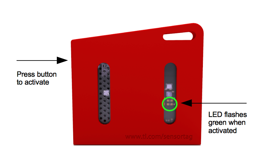
With the sketch complete, verify it to ensure there are no errors, then go over the schematics once again to ensure everything is as it should be. With that done, connect the Nano 33 IoT or the MKR WiFi 1010 to your computer and upload the sketch to it. As soon as the upload is complete, open your serial monitor for debugging, and turn on the SensorTag ensuring its within reasonable distance for Bluetooth connection to your Nano 33 IoT setup.
Turn On the SensorTag
From the serial monitor and the OLED, you should see the SensorTag connect to the Nano 33 sense IoT and you should see the data displayed on the OLED as shown below.
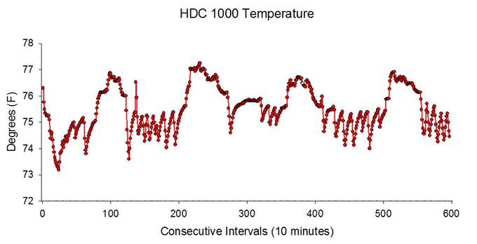
The data should also now be stored in a CSV format on the attached SD card too with timestamps that reflect the time as maintained by the RTC, and you should be able to plot it as shown in the image below.
Going Forward
While IoT provides a good way to receive data immediately and perform analysis in real-time, there are situations where it becomes impractical to send the data in real-time. For such a situation the data can be logged and then transmitted in due time, which can be achieved with a setup similar to the one described in this tutorial. Also, more sensors like the SensorTags are being developed with some based on connectivity solutions with longer ranges like LoRa. Having all of these in place means a scenario where a single datalogger can be used for multiple sensors that can be achieved.
That’s all for today’s project. Thanks for building along. Feel free to reach out to me with whatever questions you might have, via the comment section.
The electric resistance is a property that characterizes how a particular component creates an opposition to the flow of current when a voltage difference is applied to its terminals. In this tutorial, we will focus on the opposition that a resistor generates when an AC voltage is applied to it.
In the very first section, in order to get further than the Ohm’s law, a simple presentation gives some details about the concept of resistance and the resistor components. We will see in the second section the behavior similarities between the resistance in AC regime and in DC regime.
The following sections will highlight two phenomena that induce differences between the AC and DC resistance of resistors, specially when the frequency increases.
Presentation : the resistivity
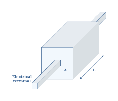
In this section, we define a little more clearly what the resistance is and on what it depends on. As the title suggests it, the primary concept is called the resistivity. Let’s consider a parallelepipedic material of cross section A and length L with two terminals such as presented in Figure 1 :
fig 1 : A resistor with electrical contacts
The resistivity ρ is expressed in Ω.m and it is an intrinsic property of the material. This means that the resistivity does not depend on the geometry. The resistivity value of any material can simply be found in online tables or in books.
Moreover, resistivity is one of the rare physical quantity that varies across so many orders of magnitude. For example, copper is one of the less resistive materials, its resistivity is ρcopper=1.7×10⁻⁸ Ω.m. On the other hand, Teflon is one of the most resistive materials with a resistivity of ρTeflon>1023 Ω.m.
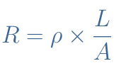
For a specific geometry, such as in Figure 1, the resistivity and resistance R are linked by the following formula given in Equation 1 :
eq 1 : Definition of the resistance
We can understand with this formula that the resistance if affected by the geometry and the intrinsic resistivity of the material :
If the length increases, the electrons have to go through more resistive material, thus the resistance increases.
If the cross section decreases, less possible path are available for the electrons (like for a simple road or a 4 lane highway), thus the resistance increases.
If the resistivity increases, the material is intrinsically more resistive, therefore the resistance increases again.
Resistors are usually made of ceramic or carbon powder, the resistivity is ρcarbon≅ 10-3 Ω.m. For example, if we choose a ratio L/A=1000, we get a resistance of a few Ohms.
Similarities in AC regime
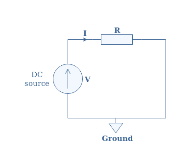
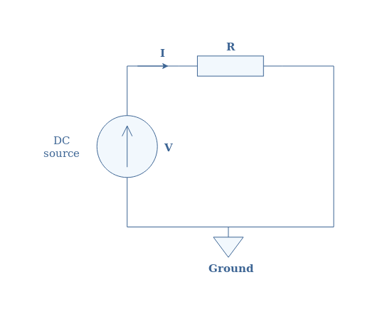
In DC regime, the resistance generated by a resistor is extremely simple to describe, it is described by Ohm’s law. It is a linear relationship between the voltage V and current I where these two quantities are linked by a factor R called the resistance such as U=R×I.
fig 2 : Illustration of a DC voltage applied to a resistor
So what happens if we replace the DC source by an AC source in Figure 2 ? Will Ohm’s law still be possible to apply ?
The answer is simple, under normal conditions of frequency and amplitude (not too high), the resistor behaves strictly the same than in DC regime. The complex impedance of the resistance is therefore a real number Z=R+j×0=U/I.
In DC regime, the power generated by heating is given by the product of voltage and current : P=U×I. This is also true in AC regime for the instantaneous power : P(t)=U(t)×I(t). However, the average power Pavg dissipated by Joule’s heating is more interesting to focus on. The formula for Pavg is given below in Equation 2 where Φ states for the phase shift between the voltage and current:
eq 2 : Expression of the average power
Since the impedance of a resistor is real, we can refer to the tutorial about complex numbers to understand that the phase shift Φ is equal to zero. The subscripts “RMS” states for Root Mean Square, its definition is fully explained in the AC waveform tutorial.
For the particular case of a purely resistive circuit, the expression of the average power reduces therefore to Pavg=URMS×IRMS.
Disparities in AC regime
We pinpoint in this last section two effects that modify the AC resistance compared to the DC resistance when the frequency of the AC source increases a lot. The section is divided in two subsections to treat these phenomena independently.
The skin effect
Before talking about this phenomenon, we need to understand its origin. This first effect is due to the law of electromagnetic induction that we have mentioned in the AC waveform tutorial.
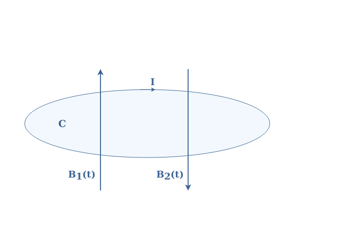
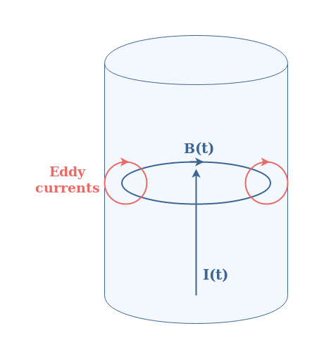
The induction law or Lenz’s law states that considering a closed electric circuit C in which a variable magnetic field B1(t) penetrates, a current I is generated in order to create an opposite magnetic field B2(t) to moderate the variation of B1(t).
fig 3 : Illustration of the induction phenomenon
This electromagnetic effect is widely present in many technologies and can be used in different ways, it is how inductor, turbines, transformers or induction cookers work.
Let’s be back now to a piece of resistive material such as already presented in Figure 1. In the same way that an alternating magnetic field generates current loops, an alternating current I(t) generates magnetic loops B(t) as well. Since magnetic loops are generated within the resistive material, it creates such as shown in Figure 3 current loops. These current loops have a particular name : they are called Eddy currents or Foucault currents.
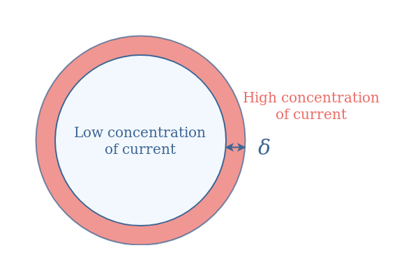
fig 4 : Illustration of the skin effect
Such currents are concentrated at the border of the resistive material such as presented in Figure 4 above. This phenomenon called skin effect tends to become more important when the frequency of the alternating current I(t) increases.
The most important parameter describing the skin effect is called the skin depth and noted δ. It denotes the thickness from the border of the resistive material where most of the Eddy currents are concentrated.
This value is proportional to 1/√f where f is the frequency. Therefore increasing the frequency tends to decrease the skin depth. When the frequency of the alternating current becomes very high, most of the current is located in a small region near the resistive material border such as depicted in Figure 5 :
fig 5 : Description of the skin depth and current distribution profile
The effective cross section A of the material becomes then smaller and therefore, according to Equation 1, the resistance increases.
For a certain value of the frequency, which depends on the material, the skin effect tends to increase the AC resistance compared to the DC resistance : RAC>RDC.
The proximity effect
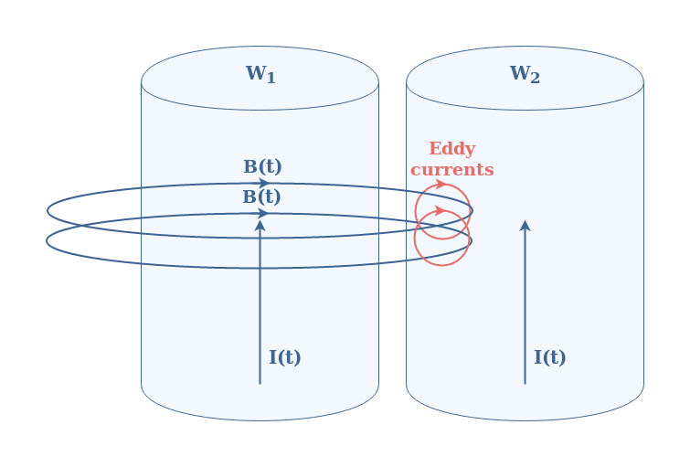
Electromagnetic induction is also the cause of another effect known as proximity effect that can greatly affect the AC resistance of a circuit. The proximity effect is observed when two or more nearby conductors are carrying current.
Let’s consider for the simplicity of the example two parallel wires W1 and W2 carrying the same AC current I(t). If the frequency of the current is high enough, a magnetic loop B(t) will be generated by W1 (also by W2 but not represented in Figure 6) around itself. If the wires are close enough, the magnetic loop will cross the second wire and generate, as explained previously, Eddy currents in W2 :
fig 6 : Illustration of the proximity effect
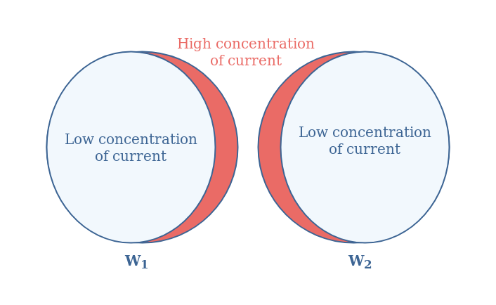
Since the effect is symmetrical, W2 also induces Eddy currents in W1. The current concentration profile would look, for this example, as illustrated in Figure 7 below :
fig 7 : Distribution of current due to the proximity effect
Such as for the skin effect, the proximity effect is the result of a modification of the distribution of current within the resistive materials that tends to increase the resistance by decreasing the effective cross section. This effect is also enhanced when the frequency increases and can lead up to one or more orders of magnitude of difference between the AC and DC resistances.
Conclusion
This tutorial has been focusing on the similarities and disparities between the value of the resistance of a resistive material in DC and AC regime.
First of all, we have presented what exactly the resistance consists of by presenting the concept of resistivity. We have seen that the resistance depends on this intrinsic property and on the geometry of the material considered.
In a second section, we investigate the AC resistance under normal operating condition (not too high frequency). Ohm’s law can be applied in AC regime such as in DC regime. Moreover, since no phase shift is observed, the expression of the power is similar than in DC regime by using the RMS values for the voltage and current quantities.
In the last section, two phenomena pinpoint the fact that when the frequency increases, the AC resistance can get much higher than the DC resistance.
The first effect is called the skin effect and is due to a redistribution of the current near the border of the conductor. This decreases the effective cross section where the current passes, which increases the resistance.
The second effect is the proximity effect and happens when two nearby conductors are simultaneously carrying an alternating current, sufficiently high enough in frequency. It leads as well to a redistribution of the current within both conductors near one of their border which, similarly than the skin effect, increases the resistance of the wires.
However, these effects only start to greatly affect the circuit when the frequency is very high. For example, at 50 Hz, cooper wires do not need to be wider than 8 mm in radius since the skin depth at this frequency is around 9 mm. At 10 MHz, this depth becomes around 21 μm, which is still not a problem of design for Printed Circuit Boards (PCB) that can go down to width of 10 μm. We can say that above 100 MHz, the skin and proximity effects related to that depth become constraining to properly design circuits.
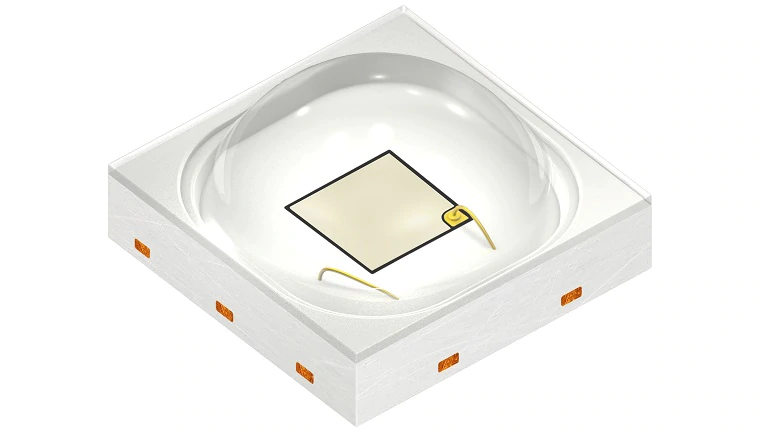
The OSCONIQ® P 3030 Colors family LED comes with well known superior robustness, high reliability, long lifetime, low thermal resistance
The OSCONIQ® P 3030 Colors family LED comes with well known superior robustness, high reliability, long lifetime, low thermal resistance. Compact and proven a 3 x 3 mm package and established a footprint. Perfectly addressing applications that demand for high efficiency and long lifetime. It features superior robustness, high reliability, long lifetime, low thermal resistance – we have transferred our special automotive experience in combining competitive lead frame technology and high-power chips in the field of high volume products for General Lighting.
Key features
Compact Footprint (3.0 mm × 3.0 mm)
Broad Range of Color Selection (449 nm – 660 nm, selected special colors)
Very Low Thermal Resistance
Maximum Driving Current up to 1 A
Additional features
Compact and proven 3 x 3 mm package and established footprint
The MAX77860 is a high-performance single input switch mode charger that features USB Type-C CC detection capability in addition to reverse boost capability and a Safeout LDO.
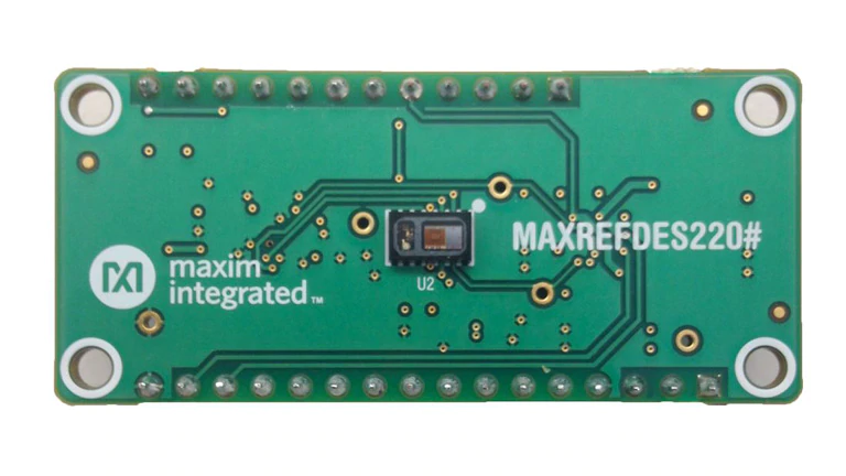
The MAXREFDES220# reference design provides everything you need to quickly prototype your product to measure finger-based heart rate and blood oxygen saturation level (SpO2).
The MAX30101 and the MAX32664 provide an integrated hardware and software solution for multiple finger-based applications. The MAX32664 firmware provides digital signal processing to process the data. The reference design also includes a tri-axis accelerometer to compensate for motion artifacts.
Key features
MAX30101 Heart Rate Monitor and Pulse Oximeter
Tiny 5.6mm × 3.3mm × 1.55mm 14-Pin Optical Module
Integrated Cover Glass for Optimal, Robust Performance
Ultra-Low Power Operation for Mobile Devices (< 1mW)
Programmable Sample Rate and LED Current for Power Savings
High SNR (Signal-to-Noise) ratio, typically greater than 80dB
MAX32664 Sensor Hub
Maxim-licensed firmware provides complete algorithmic support for finger heart rate and blood oxygen saturation calculations
Communicates with host controller over industry standard I2C interface
Secure firmware updates authenticated by dedicated bootloader
3-Axis Accelerometer Provides Greater Accuracy
Compensates for motion artifacts
A MAX32630FTHR is provided to emulate a host system for easy development.
Design files, firmware, and software can be found on the Design Resources tab. The board is also available for purchase.
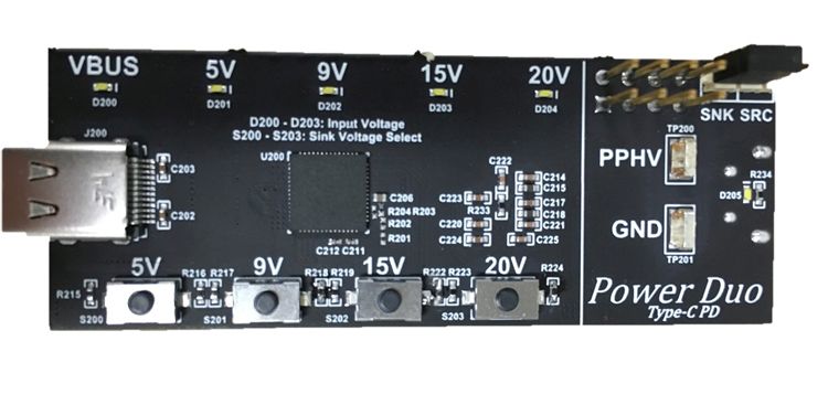
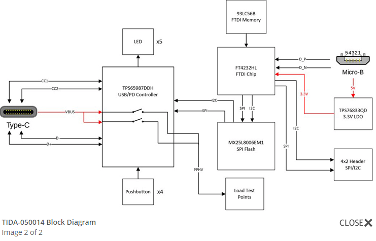
The Power DUO Sink 200W USB-C PD Reference Design is a complete USB PD Sink reference design that allows users to select their USB PD sink voltage.
This USB Powe rDelivery (PD) reference design will allow users to implement a system that requires more than 100W to operate at, while also highlighting the industries lowest RDSon solution.The design can sink all four of the standard source voltages of 5 V, 9 V, 15V, and 20 V. In standard Type-CPD operation,the design will be able to sink up to 20V/5A.When Texas Instrument’s Power DUO alternate mode is entered,the design will be able to output up to 20V/10A while simultaneously lowering the RDSon by a factor of two.
Features
Up to 200W Source or Sink
PD3.0 Compliant
Built in SPI/I2C Debugger and Programmer
Fully Configurable for any USB Type-C and Power Delivery Application
Microchip announces a new family of Serial Peripheral Interface (SPI) EERAM memory products that offers system designers up to 25 percent cost savings over the current serial Non-Volatile RAM (NVRAM) alternatives. The family introduces four reliable SPI densities to Microchip’s EERAM portfolio, ranging from 64 Kb up to 1 Mb.
High-density SPI EERAMs up to 1 Mb for task data-logging applications
SRAM content is retained during power loss without using an external battery
Automatic transfer of SRAM data to non-volatile storage as power loss is detected
Price point reduced compared to low-density NVRAM and FRAM solutions
Applications from smart meters to manufacturing lines, that require repetitive task data-logging, must be able to automatically restore content if power is disrupted during processing. Current low-density (64 Kb to 1Mb) NVRAM solutions used for these data logs are typically the highest price-per-bit memory in the resulting end products.
EERAM is a standalone non-volatile RAM memory that uses the same SPI and I2C protocols as serial SRAM, enabling devices to retain SRAM content during power loss without using an external battery. All non-volatile aspects of the part are essentially invisible to the user. When the device detects power going away, it automatically transfers the SRAM data to non-volatile storage and moves it back to the SRAM once power returns to the part. In manufacturing lines, for example, stations handle up to millions of tasks over their lifetimes and lost data during a task can require overhauling or discarding items. EERAMs automatically store SRAM content in these settings, allowing the manufacturing line to resume where the task was disrupted.
The primary reason EERAM is available at a lower price point is the use of standard Complementary Metal-oxide Semiconductor (CMOS) and Flash processes. Because these are the highest volume and most widely used processes, they offer the best reliability and lowest cost in the industry.
Alternative solutions such as Ferroelectric RAM (FRAM) use a specialty process, resulting in much higher costs and unstable long-term supply. The new EERAM family comes with Microchip’s customer-driven obsolescence practice, which helps ensure availability to customers for as long as needed.
The following devices are available in 8-pin SOIC, SOIJ and DFN packages in volume production.
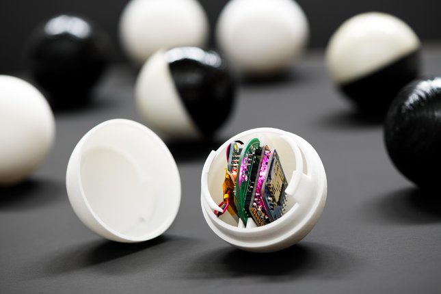
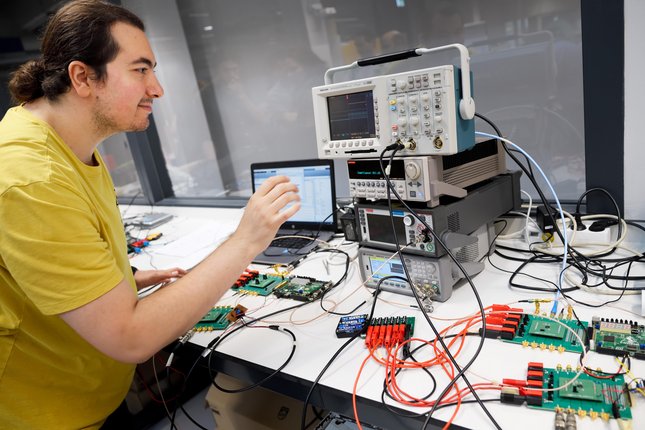
A small team of researchers led by Peter Baltus, professor of microelectronics at the department of Electrical Engineering at Eindhoven Institute of Technology, the Netherlands, has developed small circuit boards equipped with sensors that can easily fit into a small golf-sized ball. While moving inside a pipeline, these swarm of smart marbles or balls can detect any obstacles, damages or leaks that are present in the pipeline network.
When operating in an unusually difficult environment inside a pipeline, the researchers decided to use the power of AI (Artificial Intelligence). It enabled the marbles to evolve its own ability to adapt to the current situation inside the pipeline. This process was simulated accurately with software. After retrieving the realtime pipeline data, an initial model of the pipeline was developed on a computer. A programmed algorithm then simulated the environment which the marbles had to deal with. It took about 500 simulation cycles to develop an optimal configuration that almost matched the inside of the pipeline system. This simulation software was then put into the circuits within the marbles. Then the marbles were finally released in the same real pipeline system yielding significantly good results.
When you are unfamiliar with an environment, you also can’t know which features a sensor is going to need in order to explore that environment,” said Peter Baltus. “I draw a parallel with evolution because the process is so unpredictable. We don’t have a solution, so we let an algorithm do it. This algorithm mixes the most successful balls and works towards an optimum. We don’t know the results of that simulation process beforehand. Perhaps the algorithm decides to give each marble its own task, which could lead to location marbles and marbles that detect leakages. The fact that our first evolution experiment shows that the principle works are actually unbelievable, and they even evolve in the right direction as well.
The researchers came up with the idea of using low energy reversed magnetic fields with low frequency to communicate between the balls and the host. Though its range was short for this mode, the objective of exact location detection corresponding to the relative positions of the marbles was much accurate.
Phoenix demo setup, pipe-loop with sensor agents for mapping and exploring unknown water environments, by Elena Talnishnikh Integrated Circuits, group Peter Baltus, Electrical Engineering, TU Eindhoven
At first, the marbles were intended to flow smoothly with the current inside the pipeline to reduce power consumption. But, in the event of it getting stuck inside a damaged pipeline, there was no way of returning it to normal operation. And that is why the marbles were later fitted with an emergency system. When a marble gets stuck, it uses its last bit of energy to send out a distress signal to the other balls nearby. In doing so, the marble also sends all the information is collected, so that no vital information is lost.
As for the future of this new technology Baltus said, “We want to make the marbles even smaller, so that we can use them in healthcare, for example. Imagine that they’re small enough to flow through your blood vessels. That would bring entirely new possibilities to the detection of obstruction.”
At the moment, the marbles are only being used to detect leaks. But in the future, Baltus and his team look forward to developing a resin that fixes the leaks right away. More information can be found on this project page.
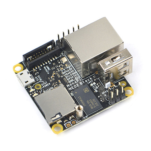
NanoPi NEO2 also known as NanoPi NEO2-LTS from FriendlyELEC is a small SBC powered by Allwinner H5 SoC with an ARM Mali-450MP GPU. It is intended for server/headless applications with Ethernet & USB ports, as well as I/O headers.
FriendlyELEC launched yet another variant called NanoPi NEO2 Black with the same form factor and Allwinenr H5 64-bit Arm SoC. Only upgrading the eMMC flash module and supporting up to 1GB RAM. There are also small alterations to the I/O headers, and featuring a black PCB instead of the blue PCB found in NEO2-LTS.
Headless applications mean the system runs without a graphical user interface (GUI). Most frequently headless applications are command-line applications or applications that are interfaced with a programming language. Especially in the professional IT world, command-line user interfaces are also common – mostly, because they can be used on servers and local PCs with a screen alike, and they are much easier to automate than GUIs.
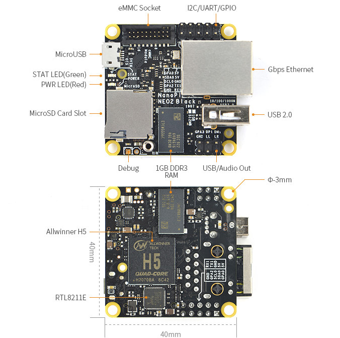
NanoPi Neo2 Black and detailed view
NanoPi NEO2 Black SBC specifications:-
SoC – Allwinner H5 quad-core Cortex A53 processor with an ARM Mali-450MP GPU
USB – 1x USB 2.0 host port, 1x micro USB OTG port, 1x USB via headers
Expansion headers –
10-pin header with I2C, UART, GPIOs, and power signals (5V in/out + GND)
6-pin header with 1x USB, Line Out (stereo), 1x GPIO
Power Supply – 5V via micro USB port or VDD pin on headers.
Dimensions – 40 x 40 mm
Weight – 16 grams
Misc – Power and system LEDs
The new NanoPi NEO2 Black is compatible with Ubuntu 18.04 (FriendlyCore) and OpenWrt (FriendlyWrt). Armbian is also supported by this board.
As to talk about the possible applications for the tiny $20 board, it ranges from networking to the home automation system. Various IoT projects are also possible because of the NanoHAT sensor modules. Existing projects based on NanoPi NEO & NEO2 should be easily ported to NanoPi NEO2 Black. More information can be found along with various board accessories details on this product page.