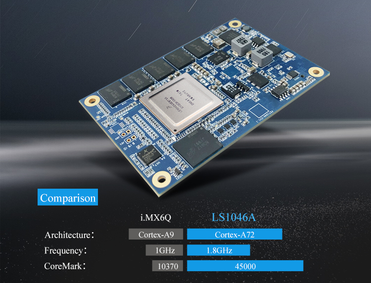
NXP LS1043A quad-core Cortex-A53 communication processor was introduced in 2014, while NXP LS1046A quad-core Cortex-A72 SoC was launched about 18 months later. Both are designed for networking equipment such as CPE (Customer Premise Equipment), routers, NAS, gateways, as well as single board computers and include one or two 10 GbE interfaces.
Forlinx Embedded has decided to leverage those two processors in their OK1043A-C and OK1046A industrial-grade single board computers designed for networking applications.
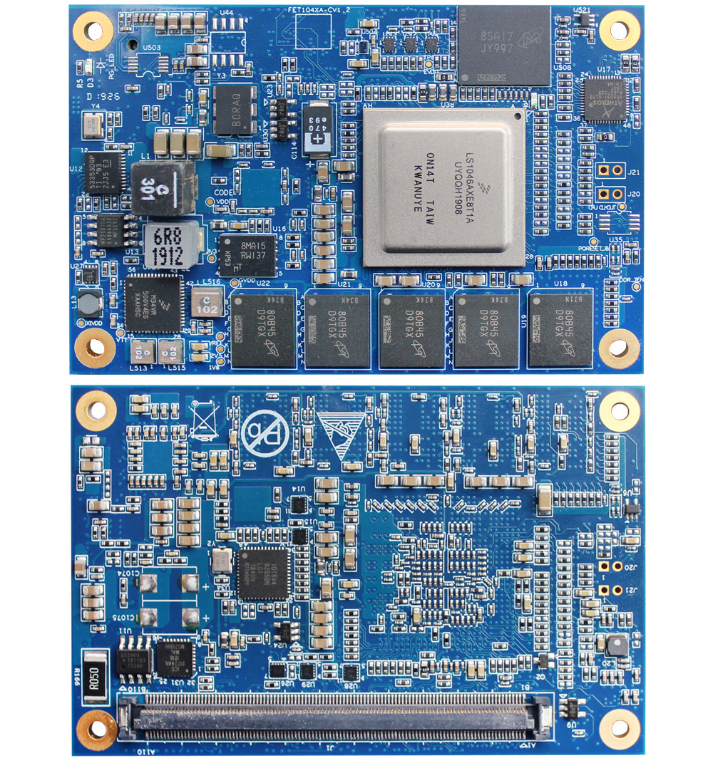
Both boards are comprised of the same baseboard and only differ by their COM-Express Mini Type 10 module which comes with the processor, memory, and flash storage.
Specifications:
COM Express Mini System-on-Module (one or the other)
FET1046A-C NXP LS1046A SoM
CPU – NXP LS1046A quad-core Cortex-A72 processor @ up to 1.8GHz
System Memory – 2GB DDR4 RAM
Storage – 8GB eMMC flash + 16MB QSPI NOR Flash
Voltage Input – 12V
Temperature Range – -40℃ to +75℃
Dimensions – 84 x 55mm
FET1043A-C LS1043A SoM
CPU – NXP LS1043A quad-core Cortex-A53 @ up to 1 .6GHz
System Memory – 2GB DDR4
Storage – 8GB eMMC flash + 16MB QSPI NOR Flash
Voltage Input – 12V
Temperature Range – -40℃ to +80℃
Dimensions – 84x 55mm
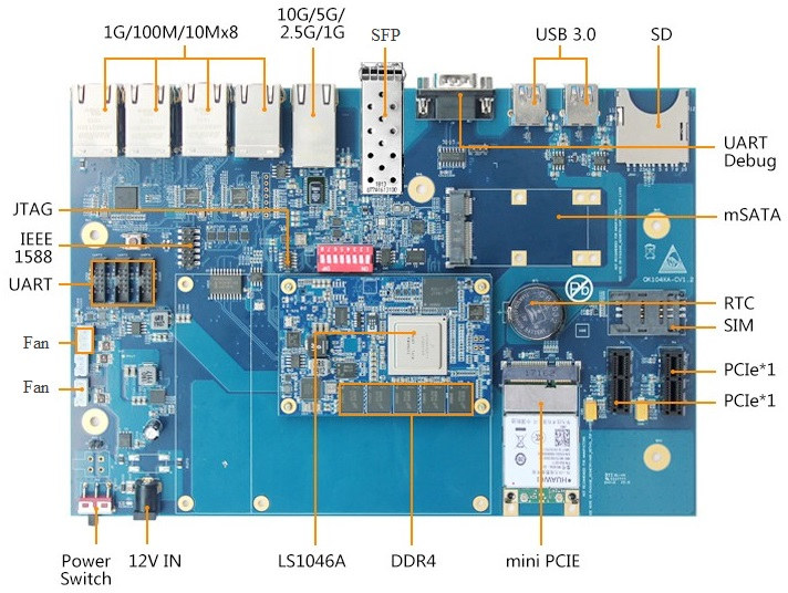
Carrier Board
Storage
SD card socket multiplexed with eMMC, bootable
1x mSATA 3.0 up to 6Gbps
Networking
Up to 6x 6 Gigabit Ethernet ports (4x from QSGMII and 2x from RGMII)
1x 10Gbps Ethernet port (RJ45)
LS1046A only – 1x 10 Gbps Ethernet Port (SFP+) for optical module or SFP-GE transceiver
USB – 2x USB 3.0 ports
Expansion
1x Mini PCIe 2.0 up to 5GT/s with USB and SIM card signals for 4G module; SIM card slot
2x PCIe 2.0 up to 5GT/s
3x UART TLL headers
Debugging – 1x RS232 debug port, JTAG header with support for NXP CodeWarrior TAP
Misc – RTC with on-board CR2032 cell, fan headers, configuration dip-switch, power switch
Power Supply – 12V via power barrel jack
Dimensions – TBD
So the main difference is that LS1043A can support up to 7 Ethernet ports (1x XFI 10Gbps Ethernet + 6x Gigabit Ethernet), while LS1046A can handle up to 8 Ethernet ports (2x XFI 10Gbps Ethernet + 6x Gigabit Ethernet).
Both boards run Ubuntu 18.04 with Linux 4.14.4 or OpenWrt 17.01 with Linux 4.14.69 , and the company provides complete BSP with source code to their customers (no public download).
Target applications include industrial routers, edge computing gateways, IP-PBX, energy management, automation, and more. Both boards and corresponding modules appear to be available now at an undisclosed price. You may find more details about OK1043A-C and OK1046A-C networking SBCs on the respective product pages here and there.
pH meters are scientific instruments used for measuring the activity and concentration of hydrogen-ions in water-based solutions, with the aim of indicating its acidity or alkalinity expressed as pH values. They find application in water & wastewater treatment, pharmaceuticals, chemicals & petrochemicals, food & beverages, mining, and agricultural processes to mention a few. For today’s tutorial, we will attempt to build an accurate, DIY version of this very useful tool.
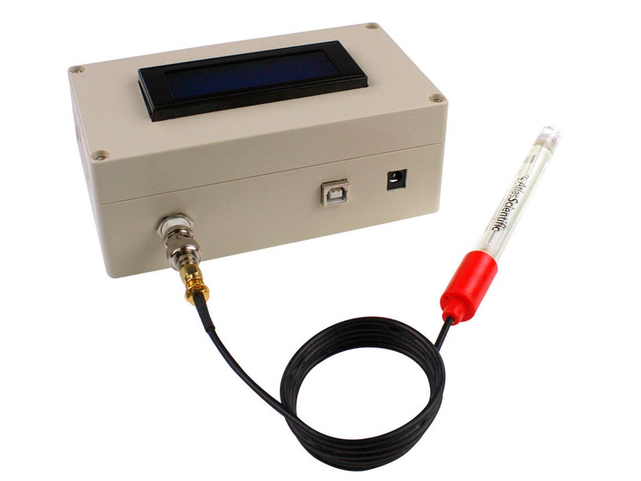
DIY pH Meter
pH meters comprises of majorly a probe and a processing unit which interprets the data from the probe and displays in a human readable format. pHmeter essentially measures the difference in electrical potential between a pH electrode and a reference electrode. As a result of this, pH meters are sometimes referred to as a “potentiometric pH meters”.
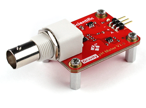
Gravity analog pH meter breakout board
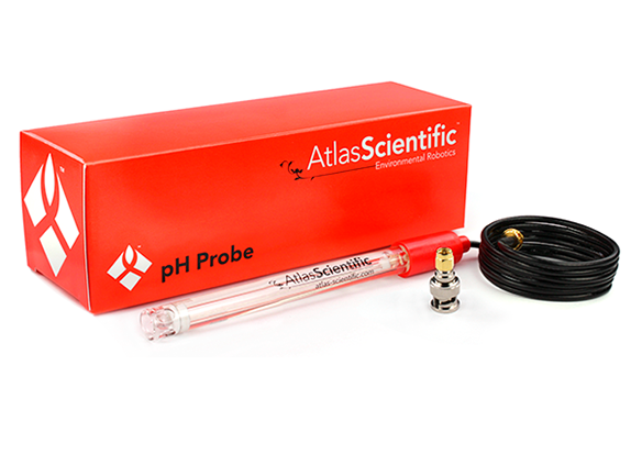
While there are several DIY pHmeter examples on the internet, today’s project will be based on the examples provided by Atlas Scientific. We will use the Atlas Scientific pH probe and their Gravity analog pH meter breakout board. The Gravity analog pH meter breakout board is a fairly accurate low-cost pH metering solution specifically designed for Students / education, Proof of concept developments and pH metering applications requiring moderate accuracy levels. It comes with a BNC port through which it can be connected to the Atlas Scientific pH probe.
Atlas Scientific pH probe
Asides the pH breakout and the probe, we will use an Arduino Uno and a 20×4 LCD display. The Arduino will serve as the brain for the project obtaining the pH level from the probe while the LCD will serve the purpose of providing visual feedback to the users as the value obtained by the Arduino will be displayed on the LCD.
To make the project neat, Atlas Scientific also created a nice enclosure and we will follow the steps outlined by them to create our own.
Ready? let’s jump in.
Required Components
We start by first getting supplies for our build. The following components are needed to build this project;
11mm standoffs and screws (comes with the pH sensor) x4
Resistors 220Ω $ 1kΩ
To reduce the workload associated with searching for the exact components used for this tutorial, I have included links through which each of the components can be bought.
Asides the components, a few tools are required for developing the enclosure, but since that is not so important we will leave it till we get to that stage.
Schematics
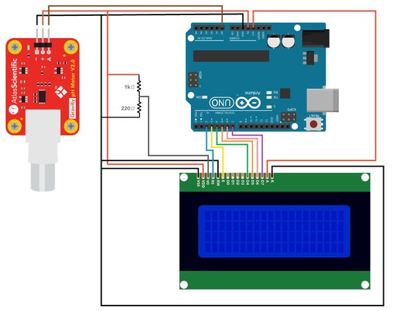
The schematics for today’s project is quite straightforward. We will connect the LCD using the 4-pin mode, while we willconnect the signal pin from the PH sensor to an analog pin on the Arduino since it’s output is analog.
Connect the components as shown in the schematics below:
Schematics
To make the schematics easy to follow, a pin map showing how the components are connected to the Arduino is provided below;
PHmeter – Arduino
+/VCC - 5V
-/GND - GND
A/OUT - A0
LCD – Arduino
K - GND
A - 3.3V
D7 - D7
D6 - D6
D5 - D5
D4 - D4
E - D3
RS - D2
R/W - GND
VSS - GND
VDD - 5V
VO - 5V Via Resistors as voltage dividers
Go over the connections when done to ensure everything is as it should be.
Enclosure Design
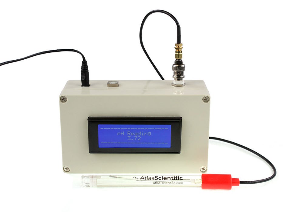
With the connections ready, to make the project neat and presentable an enclosure was created. The enclosure is based on the popular abs plastic enclosures and it was modified with drills and other tools so it accommodates the screen and fits perfectly for other projects. A picture of the completed enclosure is displayed in the image below.
DIY pH Meter
To modify the ABS enclosure for the desired neat and clear shape as shown in the picture above, different kind of tools were used including; a Drill, drill bits, drywall cutter bits, files, screwdrivers, benchtop vise, band saw, glue gun and glue stick, soldering iron and solder, digital caliper, ruler. While having these tools makes the process of making the enclosure easier and faster, feel free to use make shift tools that in one way or the other, help achieve the goal of a neat enclosure.
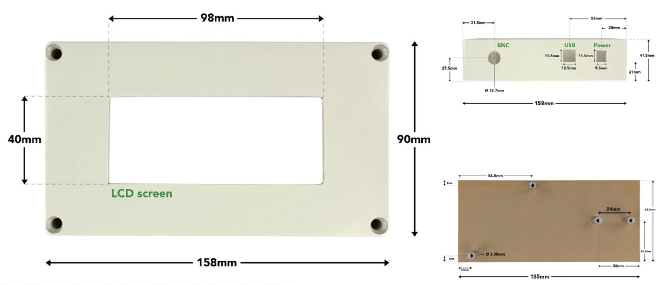
All of the modifications made to the ABS enclosure are based on the diagram below. You may need to zoom in to see the dimensions properly.
You can follow the steps below to achieve this with good precision. Feel free to use other tools/makeshift tools where needed.
Cut opening for the LCD
The LCD is placed in the top portion (cover) of the enclosure. Center a 98x40mm rectangle on the cover.
Put the piece in the vise and drill a 3.2mm (1/8″) pilot hole in the rectangle that was marked off.
Use this pilot hole as the start point for the 3.2mm (1/8″) drywall cutting bit. Since this a small job, we will use the bit on the hand drill rather than a drywall cutting machine. Work on the inside of the rectangle instead of the lines as it may be a bit difficult to cut in a straight manner with this bit on the drill.
Next, use a hand file to remove the excess material and shape the rectangle to the required size.
Cut openings for BNC connector and Arduino ports
The openings for the BNC connector and Arduino ports are on the side of the bottom portion of the enclosure.
Using the dimensions provided above, mark the center point for the circle and outlines for the two rectangles.
Put the piece in the vice and cut the openings. The circular opening is made using drill bits. The rectangular ones are made by following a similar process used to make the opening for the LCD.
Outfit the base plate to mount components
The base plate is used to mount the Arduino, pH sensor and mini breadboard. 6.4mm (1/4″) thick acrylic sheet is used.
Using a band saw, cut the acrylic sheet to 135×62.5mm.
Mark off the positions for the four holes as shown. Drill 2.38mm (3/32″) diameter holes. Countersink the holes on one side of the plate to a depth of 3mm and diameter of 4.4mm (11/64″). This is necessary to keep a flat undersurface when the screws are inserted to hold the standoffs.
Attach the 11mm standoffs using the provided screws. The pH sensor comes with 4 standoffs and screws. Use two of them for the Arduino.
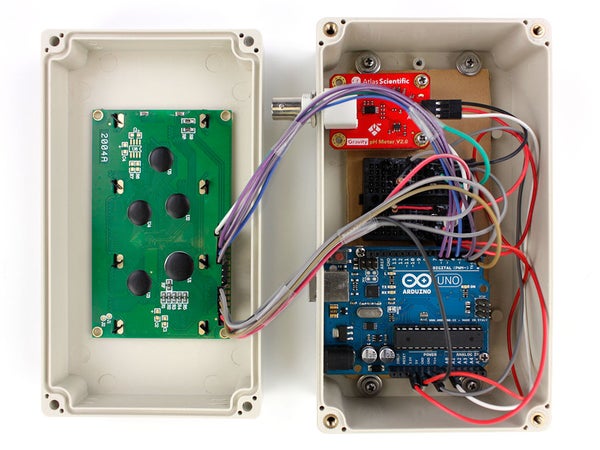
With the enclosure complete, arrange the components inside it such that the set up looks like the image below.
Assembling the components in the Enclosure
Code
The code for today’s project is quite straightforward. Our tasks as mentioned during the introduction is to collect the pH level using the pH meter and display on the attached LCD.
We will use the Arduino IDE for the development of the code and will use 2 major libraries; the Liquid Crystal Display library and the Atlas gravity sensor library. The liquid crystal display library is used to reduce the amount of work/code that is required to get the Arduino to interact with the LCD, while the Atlas Gravity Sensor Library makes it easy to interface with the PH meter and obtain data. The Liquid Crystal Library usually comes with the Arduino IDE but just in case it didn’t, you can always install it via the Arduino Library manager. The Atlas Gravity Sensor library, on the other hand, needs to be installed manually, as such, you will need to download it from the attached link, unzip it and copy it’s content into the Arduino Library folder. The library folder is usually in the same folder as your Arduino Sketches.
With the libraries installed, we can now proceed to writing the code.
The sketch starts by including the libraries that will be used.
#include "ph_grav.h"                                  //header file for Atlas Scientific gravity pHsensor
#include "LiquidCrystal.h"                            //header file for liquid crystal display (lcd)
Next, we declare some of the variables that will be used during the code, declare the analog pin of the Arduino to which the PH sensor analog output pin is connected, and create instances of both the Atlas Gravity Sensor Library and the Liquid Crystal Library.
String inputstring = "";                              //a string to hold incoming data from the PC
boolean input_string_complete = false;                //a flag to indicate have we received all the data from the PC
char inputstring_array[10];                           //a char array needed for string parsing
Gravity_pH pH = A0;                                   //assign analog pin A0 of Arduino to class Gravity_pH. connect output of pH sensor to pin A0
LiquidCrystal pH_lcd(2, 3, 4, 5, 6, 7);               //make a variable pH_lcd and assign arduino digital pins to lcd pins (2 -> RS, 3 -> E, 4 to 7 -> D4 to D7)
With those done, we proceed to to the void setup() function. We start the function by initializing serial communication which will is used for debug purposes, and the LCD display on which a splash/initialization screen is displayed.
void setup() {
  Serial.begin(9600);                                 //enable serial port
  pH_lcd.begin(20, 4);                                //start lcd interface and define lcd size (20 columns and 4 rows)
  pH_lcd.setCursor(0,0);                              //place cursor on screen at column 1, row 1
  pH_lcd.print("--------------------");               //display characters
  pH_lcd.setCursor(0,3);                              //place cursor on screen at column 1, row 4
  pH_lcd.print("--------------------");               //display characters
  pH_lcd.setCursor(5, 1);                             //place cursor on screen at column 6, row 2
  pH_lcd.print("pH Reading");                         //display "pH Reading"
lastly the PH meter is initialized and the control commands for calibration are displayed on the serial monitor.
if (pH.begin()) { Serial.println("Loaded EEPROM");}
  Serial.println(F("Use commands \"CAL,4\", \"CAL,7\", and \"CAL,10\" to calibrate the circuit to those respective values"));
  Serial.println(F("Use command \"CAL,CLEAR\" to clear the calibration"));
 }
Up next is the void loop() function.
The void loop function is quite straight forward. We start by checking if any calibration parameter has been received over the serial monitor. If yes, the data is parsed as an argument into the parse_cmd function where it is used to set the level of calibration required.
void loop() {

  if (input_string_complete == true) {                //check if data received
    inputstring.toCharArray(inputstring_array, 30);   //convert the string to a char array
    parse_cmd(inputstring_array);                     //send data to pars_cmd function
    input_string_complete = false;                    //reset the flag used to tell if we have received a completed string from the PC
    inputstring = "";                                 //clear the string
  }
Next, the PH level is obtained from the PHmeter using the ph.read_ph() function. The values obtained is then displayed on the serial monitor and on the LCD.
  Serial.println(pH.read_ph());                       //output pH reading to serial monitor
  pH_lcd.setCursor(8, 2);                             //place cursor on screen at column 9, row 3
  pH_lcd.print(pH.read_ph());                         //output pH to lcd
  delay(1000);
}
Other parts of the code are the serialEvent() function which is used to obtain user input from the Serial Monitor, and the parse_cmd() function which takes in the data from the serial port and uses it to set the calibration level of the PHmeter.
void serialEvent() {                                  //if the hardware serial port_0 receives a char
  inputstring = Serial.readStringUntil(13);           //read the string until we see a <CR>
  input_string_complete = true;                       //set the flag used to tell if we have received a completed string from the PC
}

void parse_cmd(char* string) {                      //For calling calibration functions
  strupr(string);                                   //convert input string to uppercase

  if (strcmp(string, "CAL,4") == 0) {               //compare user input string with CAL,4 and if they match, proceed
    pH.cal_low();                                   //call function for low point calibration
    Serial.println("LOW CALIBRATED");
  }
  else if (strcmp(string, "CAL,7") == 0) {          //compare user input string with CAL,7 and if they match, proceed
    pH.cal_mid();                                   //call function for midpoint calibration
    Serial.println("MID CALIBRATED");
  }
  else if (strcmp(string, "CAL,10") == 0) {         //compare user input string with CAL,10 and if they match, proceed
    pH.cal_high();                                  //call function for highpoint calibration
    Serial.println("HIGH CALIBRATED");
  }
  else if (strcmp(string, "CAL,CLEAR") == 0) {      //compare user input string with CAL,CLEAR and if they match, proceed
    pH.cal_clear();                                 //call function for clearing calibration
    Serial.println("CALIBRATION CLEARED");
  }
}
The complete code for the project is provided below and also attached under the download section.
/*
Once uploaded, open the serial monitor, set the baud rate to 9600 and append "Carriage return"
The code allows the user to observe real time pH readings as well as calibrate the sensor.
One, two or three-point calibration can be done.

Calibration commands:
 low-point: "cal,4"
 mid-point: "cal,7"
 high-point: "cal,10"
 clear calibration: "cal,clear"
*/

#include "ph_grav.h"                                  //header file for Atlas Scientific gravity pH sensor
#include "LiquidCrystal.h"                            //header file for liquid crystal display (lcd)

String inputstring = "";                              //a string to hold incoming data from the PC
boolean input_string_complete = false;                //a flag to indicate have we received all the data from the PC
char inputstring_array[10];                           //a char array needed for string parsing
Gravity_pH pH = A0;                                   //assign analog pin A0 of Arduino to class Gravity_pH. connect output of pH sensor to pin A0
LiquidCrystal pH_lcd(2, 3, 4, 5, 6, 7);               //make a variable pH_lcd and assign arduino digital pins to lcd pins (2 -> RS, 3 -> E, 4 to 7 -> D4 to D7)


void setup() {
  Serial.begin(9600);                                 //enable serial port
  pH_lcd.begin(20, 4);                                //start lcd interface and define lcd size (20 columns and 4 rows)
  pH_lcd.setCursor(0,0);                              //place cursor on screen at column 1, row 1
  pH_lcd.print("--------------------");               //display characters
  pH_lcd.setCursor(0,3);                              //place cursor on screen at column 1, row 4
  pH_lcd.print("--------------------");               //display characters
  pH_lcd.setCursor(5, 1);                             //place cursor on screen at column 6, row 2
  pH_lcd.print("pH Reading");                         //display "pH Reading"
  if (pH.begin()) { Serial.println("Loaded EEPROM");}
  Serial.println(F("Use commands \"CAL,4\", \"CAL,7\", and \"CAL,10\" to calibrate the circuit to those respective values"));
  Serial.println(F("Use command \"CAL,CLEAR\" to clear the calibration"));
 }


void loop() {

  if (input_string_complete == true) {                //check if data received
    inputstring.toCharArray(inputstring_array, 30);   //convert the string to a char array
    parse_cmd(inputstring_array);                     //send data to pars_cmd function
    input_string_complete = false;                    //reset the flag used to tell if we have received a completed string from the PC
    inputstring = "";                                 //clear the string
  }
  Serial.println(pH.read_ph());                       //output pH reading to serial monitor
  pH_lcd.setCursor(8, 2);                             //place cursor on screen at column 9, row 3
  pH_lcd.print(pH.read_ph());                         //output pH to lcd
  delay(1000);
}

void serialEvent() {                                  //if the hardware serial port_0 receives a char
  inputstring = Serial.readStringUntil(13);           //read the string until we see a <CR>
  input_string_complete = true;                       //set the flag used to tell if we have received a completed string from the PC
}

void parse_cmd(char* string) {                      //For calling calibration functions
  strupr(string);                                   //convert input string to uppercase

  if (strcmp(string, "CAL,4") == 0) {               //compare user input string with CAL,4 and if they match, proceed
    pH.cal_low();                                   //call function for low point calibration
    Serial.println("LOW CALIBRATED");
  }
  else if (strcmp(string, "CAL,7") == 0) {          //compare user input string with CAL,7 and if they match, proceed
    pH.cal_mid();                                   //call function for midpoint calibration
    Serial.println("MID CALIBRATED");
  }
  else if (strcmp(string, "CAL,10") == 0) {         //compare user input string with CAL,10 and if they match, proceed
    pH.cal_high();                                  //call function for highpoint calibration
    Serial.println("HIGH CALIBRATED");
  }
  else if (strcmp(string, "CAL,CLEAR") == 0) {      //compare user input string with CAL,CLEAR and if they match, proceed
    pH.cal_clear();                                 //call function for clearing calibration
    Serial.println("CALIBRATION CLEARED");
  }
}
Calibration
To ensure the accuracy of the results from the pH meter, there is a need to accurately calibrate the device. pH meters are calibrated across 3 levels; 4, 7, and 10 using standard buffer solutions that already exists at that PH level. These standard solutions are sometimes provided by the sellers of the PH sensor but when not provided, you can always get them from your local chemical stores.
To calibrate the meter, upload the sketch we developed above to your Arduino. Take some time to ensure the components are properly connected before doing this. When sketch upload is complete, open the serial monitor, based on our code the serial monitor will prompt you to enter the calibration values, with samples showing how to enter them correctly. When at this stage, follow the steps below to calibrate the meter with the three buffer solutions.
Remove the soaker bottle and rinse the pH probe
Start with the standard buffer solution for pH4. Pour some of the pH 4 solution, enough to cover the probe, into a cup.
Place the probe in the cup and stir it around to remove trapped air. Observe the readings on the serial monitor and leave the probe there till the readings stabilize.
When the readings become stable, enter the command cal,4 into the serial monitor to instruct it to save that value as the calibration value for pH4.
Repeat these steps with the pH7 and pH10 solutions, ensuring you rinse the probe as you move from one solution to the other.
With these done, the pH meter is now calibrated and should be able to give the correct pH level for any solution the probe is tested with. The calibration values are saved on the Arduino’s EEPROM so they are not lost when the meter is disconnected from power. This makes calibration not necessary before every use but you should re-caliberate the system again after some time, so you can always enter the cal,clear command on the serial monitor to clear the previous stored calibration values and repeat the steps explained above.
Demo
With the code uploaded and calibration done, you can now go ahead and dip the probe into any solution you desire and you should see the pH value displayed on the LCD like shown in the image below.
The accuracy of the pHmeter varies with temperature, as such, it is important to note that the sensor used in this project has an accuracy of +/- 0.2% and that the pH meter will operate at this accuracy level when the temperature range is between 7 – 46°C. Outside of this range, the meter will have to be modified to compensate.
Going forward, while the scope of this project is limited to pH value, you can choose to add several other sensors to make the project more useful. A good example of sensors that could be added for more value include temperature and humidity sensors.
That’s it for this tutorial, thanks for reading. Is there something I missed out, or you have one issue or the other implementing the project? feel free to reach out to me via the comment section.
In the previous tutorials, an important link has been established between the conduction angle of an amplifier and it’s efficiency. Indeed, high conduction angles-based amplifiers offer a very good linearity such as the class A Amplifiers but present a very limited efficiency, generally around 20 to 30 %. As the conduction angle is decreased, high efficiencies are reached such as with the class C amplifiers.
A conduction angle that tends to 0° is therefore desirable to achieve 100 % of efficiency. However, as we have seen with the class C amplifiers, this cannot be implemented since no power is delivered to the load.
Class D amplifiers precisely solve this problem by functioning with a different method than traditional classes A, B, AB or C amplifiers. In the first section, the simplified architecture of a class D amplifiers along with its general functioning are presented. As we will see during this section, class D amplifiers are composed of three different main modules. The next sections are therefore focused on each of these modules to understand how the signal is transformed during the class D amplification process. A little note about the efficiency of this amplifier is given in the last section. Finally, this information is synthesized in a conclusion that summarizes the global transformation of the signal.
Presentation of the Class D amplification
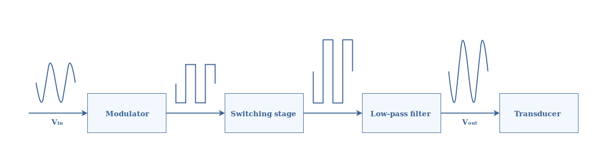
Class D amplifiers generally consists of three different modules : a modulator, a switching stage and a low-pass filter. The signal path along with the succession of these different modules is presented in Figure 1 below :
fig 1 : Flowchart of a class D amplifier
While classic amplifiers accept as an input a sinusoidal signal, Class D amplifiers previously transform it through a modulator into a rectangular signal. We will see in the dedicated section that the view proposed in Figure 1 concerning the modulation is oversimplified.
The switching stage is where the amplification takes places thanks to transistors. We present in detail in the section dealing with this stage that the transistors work in a particular regime and a complementary configuration in order to amplify correctly the rectangle signal.
Finally, a low-pass filter is used in order to restore the sinusoidal shape of the signal. Moreover, this final stage eliminates undesirable harmonics than may have been generated during the amplification process.
Modulation
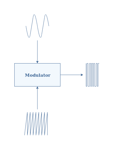
Many modulations techniques exist, however the most common and widely used for many applications is the Pulse Width Modulation (PWM). A simple graph representing the PWM is shown in Figure 2 below :
fig 2 : Principle of a PWM modulator
This technique consists in comparing the input sinusoidal signal with a high frequency triangular signal commonly called carrier obtained from an independent generator. In order to be consistent with Shannon’s theorem, the frequency of the carrier signal must be at least twice as high as the sinusoidal signal frequency.
The output of the modulator is obtained by doing the following comparison between these two signals :
If the sine is above the carrier signal, the output is equal to 1
Otherwise, the output is equal to 0
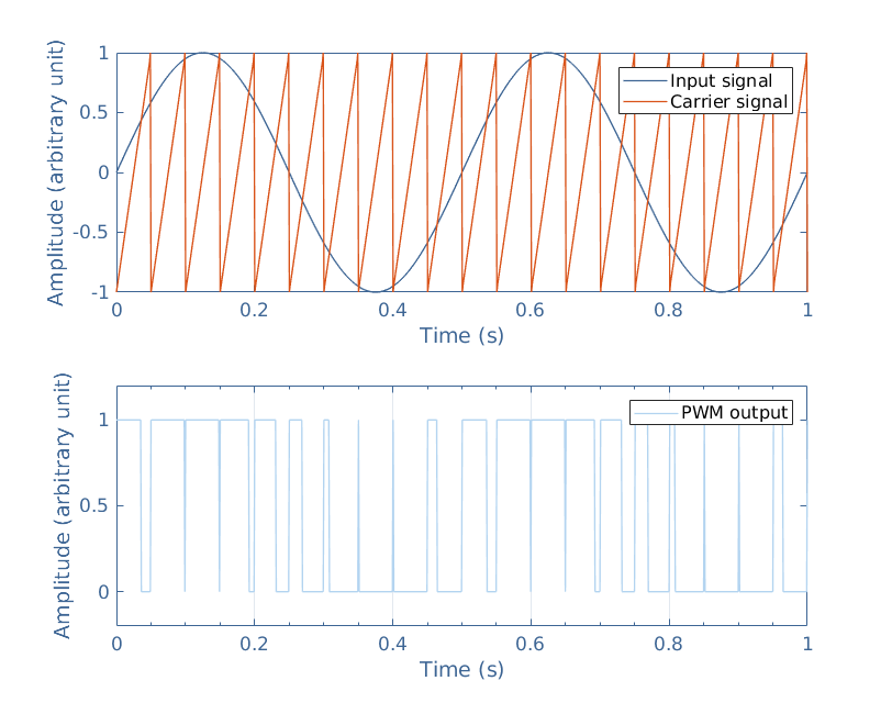
During the course of this tutorial, the transformation of the signal will be tracked by plotting every step of the amplification with the MatLab® software. In the Figure 3 below, an input signal of frequency 2 Hz is plotted along with a carrier signal of frequency 20 Hz. Moreover, the PWM output is plotted by doing the comparison explained previously.
fig 3 : PWM input and output. Plotted with MatLab®
It is important to note that the frequency of the PWM output is the same as the carrier frequency. The duty cycle is the number characterizing the proportion where the signal value is 1 during a period. For example, if the pulse is symmetrical, half of the signal will be 1 and half 0, the duty cycle is therefore 50 % or 0.5. In the case of a PWM, while the frequency is constant, the duty cycle varies.
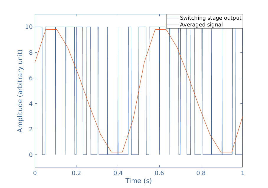
We can note that when the input signal is maximum, the PWM duty cycle tends to 1 and at the opposite, tends to 0 when the input signal is minimal. Therefore, the duty cycle of the PWM is directly related to the original shape of the sine signal. This affirmation can indeed be confirmed with a simple algorithm that averages the PWM output independently for each cycle, the result is plotted and shown in Figure 4 :
fig 4 : Average operation on the PWM signal
It is clear in this figure that when averaging the PWM signal, the sine shape of the original signal appears again. In real circuits, this operation is done by a filter as we will see in the section “Filtering”.
Amplification
Since the carrier signal is usually chosen such as its frequency is much higher than the input signal, the PWM output to amplify can be above the high cutoff frequency of a BJT-based amplifier (refer to the Frequency Response tutorial). This is the reason why high frequency MOS transistors are preferred over the classical bipolar-based amplifiers for class D amplification.
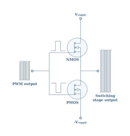
In a class D amplifiers, one NMOS and one PMOS are connected in a push-pull configuration as shown in Figure 5 :
fig 5 : Push-pull configuration of the amplification stage
Like for a class B amplifier, the complementary transistors are biased in such a way that the NMOS amplifies only positive half-waves and the PMOS only the negative half-waves. This amplification stage is also called the switching stage because the transistors behave precisely as switches : they are either fully ON (short circuit) or OFF (open circuit).
Filtering
In order to recover the original sine shape of the signal, the amplified pulse signal must be processed by a filter. This filter should respect some conditions :
Suppress the high frequencies above the normal bandwidth (midrange frequencies) of the amplifier, specially the carrier frequency and its harmonics.
Reproduce the midrange frequencies of the amplifier with a good level of gain. For example 20 Hz – 20 kHz for an audio amplifier.
Achieve a maximally flat band for the midrange frequencies.
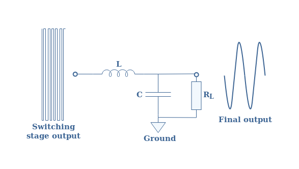
This kind of filter is commonly known as a Butterworth filter. The typical filter used to fulfill these requirements is a parallel LC circuit. When connected in parallel to a load RL, it actually can be seen as an RLC filter.
fig 6 : Low-pass L//C filter
The bandwidth of this filter is characterized by its cutoff frequency fc at -3 dB that satisfies the Equation 1 :
eq 1 : Cutoff frequency of the low-pass filter
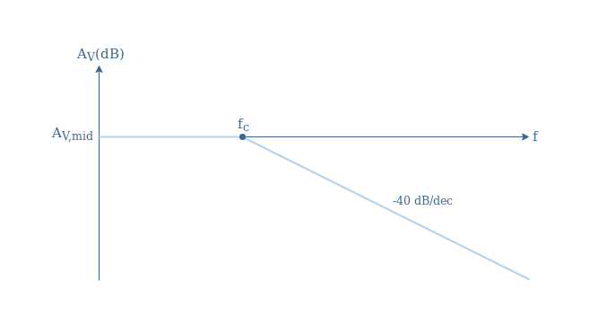
Moreover, since the RLC circuit is a second-order filter, a strong roll-off of -40 dB/dec is observed above fc. An asymptotic diagram of the frequency response of this filter is given is Figure 7 :
fig 7 : Second order Butterworth filter frequency response
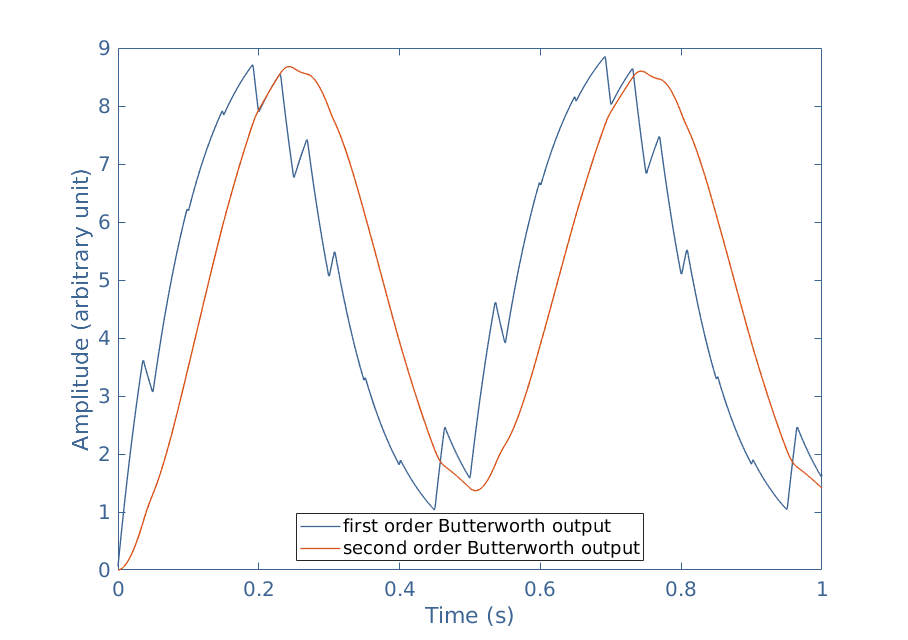
Several levels of parallel LC configurations are appreciated since each level increases the order of the filter and therefore the quality of filtration. In Figure 8, we can note the difference between the output resulting of a first or second order Butterworth filter applied to our example :
fig 8 : Difference of output between a first and second order Butterworth filter
Since the input signal has a frequency of 2 Hz and the carrier frequency is 20 Hz, a cutoff frequency of 4 Hz has been chosen for this filter. We can highlight the fact that a first order filter is not appropriate since it does not attenuate the carrier frequency enough while the second order filter output is much more sinusoidal.
Efficiency
The original way of functioning of the class D amplifier brings its efficiency to very high levels. This high efficiency is explained by the fact that the transistors behave nearly as ideal switches :
When they are OFF, no current IDS flows between the drain and the source.
When they are ON, no voltage VDS is observed across the drain and the source.
Therefore, no power VDS×IDS is dissipated in form of losses (heat). Typically the efficiency of class D amplifiers is above 90 %.
Conclusion
Class D amplifiers work very differently than the other typical classes (A,B,C). They are indeed, highly non-linear and incorporate special modules to treat the signals.
The first operation to be done is called a Pulse Width Modulation (PWM) and consists in comparing the input signal with a high frequency triangular signal. Whether the input is above the carrier or under, a new signal called the PWM output is generated and consists of a rectangular signal with the same frequency of the carrier but with a variable duty cycle. This signal is directly related to the original shape of the sine input.
Before getting back a sine signal, a switching stage made with two complementary NMOS and PMOS in a push-pull configuration amplifies the PWM output. The particularity of the transistors is that they switch between being fully ON or OFF, and they never work in their linear zone.
With this amplified pulse signal, a last stage that consists of a L//C circuit that acts as a Butterworth filter to recover the original sine shape. It is important to correctly set the cutoff frequency to eliminate the carrier frequency and its related harmonics. Moreover, a high order Butterworth filter is preferred to avoid as much as possible of distortion.
Finally, we have noted that the efficiency of this amplifier is noticeably higher than the typical classes because of the low power dissipation made possible by the switching behavior of the transistors. This fact is a great advantage in the design of class D amplifier : they do not require heavy and bulky heat sinks.
Due to its many advantages, class D amplifiers can be found in many daily applications : in mobile phones and many audio devices such as earphones, car radios etc …
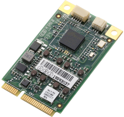
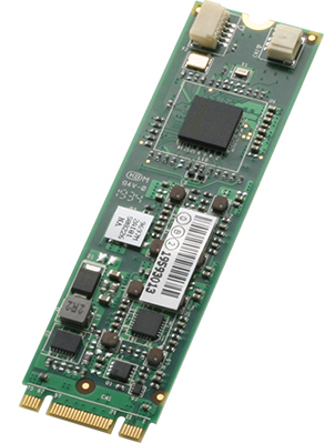
Aaeon’s M.2 and mini-PCIe “AI Edge Computing Modules” are based on Kneron’s energy-efficient, dual Cortex-M4-enabled KL520 AI SoC, which offers 0.3 TOP NPU performance on only half a Watt. by Eric Brown @ linuxgizmos.com
Aaeon took an early interest in edge AI acceleration with Arm-based Nvidia Jetson TX2 based computers such as the Boxer-8170AI. More recently, it has been delivering M.2 and mini-PCIe form-factor AI Core accessories for its Boxer computers and UP boards equipped with Intel Movidius Myriad 2 and Myriad X Vision Processing Units (VPUs). Now, it has added another approach to AI acceleration by launching a line of M.2 and mini-PCIe AI acceleration cards built around Kneron’s new KL520 AI SoC.
Aaeon’s AI Edge Computing Modules featuring the KL520 AI SoC are available for order at an undisclosed price. Presumably, these will eventually be available as individually price accessories for UP boards and the like. More information may be found in Aaeon’s announcement and on its preliminary product pages for the M2AI-2280-520, M2AI-2242-520, and Mini-AI-520 modules. More on the KL520 AI SoC may be found on Kneron’s website.
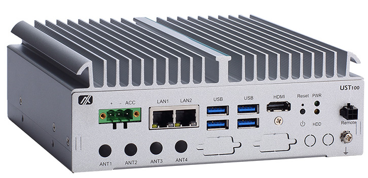
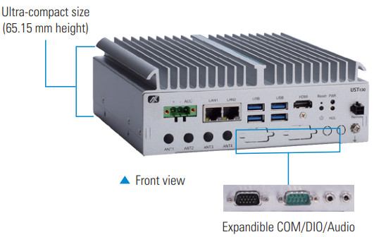
Axiomtek – a world-renowned leader relentlessly devoted in the research, development and manufacture of series of innovative and reliable industrial computer products of high efficiency – is proud to unveil UST100-504-FL, an extremely compact fanless embedded system for in-vehicle edge computing and video analytics applications. This ruggedized in-vehicle system is certified with CE and FCC and is in compliance with ISO 7637-2. Axiomtek’s UST100-504-FL features a single-sided I/O design for space-limited vehicle applications. The high-performance vehicle PC is powered by the LGA1151 socket 7th/6th generation Intel® Core™ or Pentium® processor with up to 35W TDP and comes with the Intel® H110 chipset. Thanks to its ruggedized structure and outstanding system design, the UST100-504-FL is able to operate under a wide temperature range from -40°C to +60°C and vibration of up to 3 Grms for extreme harsh environment.
“This embedded system, which is only 65 mm height, is supremely qualified for edge computing and video analytics on police and emergency vehicles. In addition, its top cover adopts the slide rail design which allows for quick and easy maintenance to the hard disk drive and mini PCIe expansion card,” said Sharon Huang, a product manager of Product PM Division at Axiomtek.” Furthermore, it comes with intelligent power management for ACC on/off delay, shutdown delay and over/under voltage protection.”
The development-friendly UST100-504-FL comes with one DDR4-1866/2133/2400 SO-DIMM slot with up to 16GB of system memory. It has three PCI Express Mini Card slots and two internal SIM card slots for wireless communication capabilities. It is equipped with one DB9 Serial console or RS-232/422/485, one HDMI 1.4b, one Mic-in, one Line-out, two RJ-45 10/100/1000 Mbps Ethernet ports, four USB 3.0, and one DB9 4-in/4-out programmable DIO. The fanless box system offers one reset button, one power switch, one remote switch and four antenna openings. It also supports 12 or 24 VDC power input in the terminal block with ACC ignition for power management for vehicle applications. Besides, the ultra-compact in-vehicle PC is compatible with Windows® 10 64-bit, Windows® 7 64-bit and Ubuntu 18.04. This reliable fanless system provides an ideal in-vehicle solution for video analytics and peripheral integration.
Advanced Features:
CE, FCC certified; ISO 7637-2 compliant
LGA1151 7th/6th gen Intel® Core™ and Pentium® processors (up to 35W) with Intel® H110
Fanless and wide operating temperatures from -40°C to +60°C
12/24 VDC power input, with power management (ACC ignition)
Single-sided I/O design for easy maintenance
Expansion capability for three PCI Express Mini Card slot and two internal SIM card slot
No price was supplied for the “coming soon” UST100-504-FL. More information may be found in Axiomtek’s announcement and product page.
Axiomtek’s UST100-504-FL is now available for purchase. For more product information or customization services, please visit our global website at www.axiomtek.com or contact one of our sales representatives at info@axiomtek.com.tw.
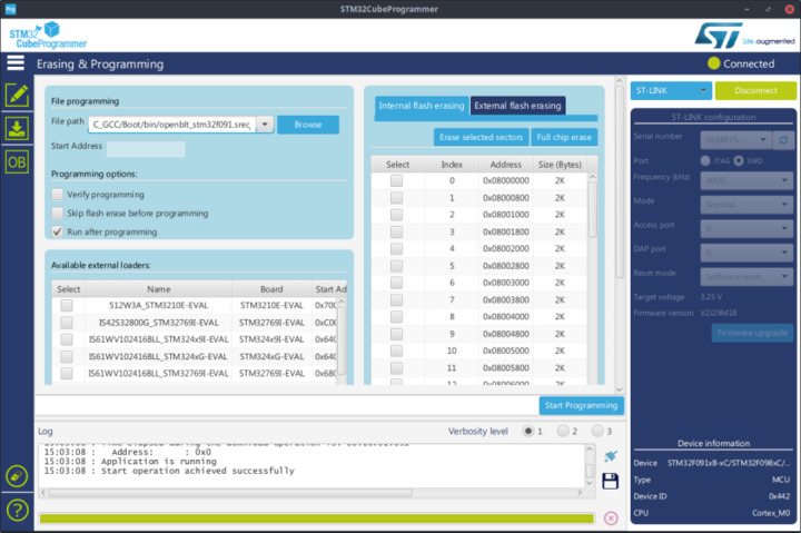
STMicroelectronics is pleased to inform us that the latest version of our all-in-one multi-OS software tool STM32CubeProgrammer is available. [Download now]
This new release:
Allows developers to seamlessly program STM32L5 and STM32WB50 (expected Q4 2019) internal and external memories, as well as the STM32MP1 series’ external flash memories.
Supports the STLINK-V3SET and STLINK-V3MINI debugging and programming probes.
Includes Over-The-Air firmware upgrade for STM32WB5x wireless MCUs.
Includes the Trusted Package Creator software tool to perform firmware IP encryption using AES-GCM key.
Manages authentication and licensing with the STM32HSM companion hardware security module to allow OEMs to restrict the number of devices that can be programmed.
The STM32CubeProgrammer release 2.2 comes in Graphical User Interface (GUI) and in Command-Line Interface (CLI) versions to ease programming automation through scripting.
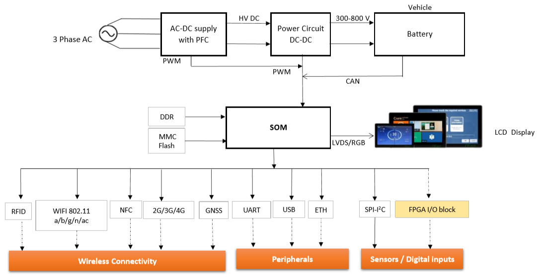
Technology is continuing to transform the automotive industry, particularly the EV segment. The decrease in battery cost and increase in battery capacity, coupled with other advantages such as zero-emission, noiseless operation, and overall cost savings have led to EVs becoming mainstream in India and globally. At the same time, more and more EV charging stations are being set up throughout the country to facilitate fast and easy charging of EVs. Subsequently, the EV charging infrastructure (EVSE system) is rapidly evolving, integrating enhanced features and providing more value-added services to the customers.
iWave Systems, a Bangalore based leading embedded solutions provider company has always been at the forefront of developing unique solutions for the automotive industry. With a broad portfolio of industrial and automotive grade modules (SOM, SBC, Development platforms, and ODM solutions), the company is uniquely positioned to empower the development of advanced and cost-effective solutions for emerging EV charging station requirements.
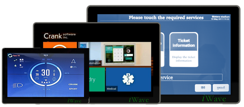
One of the most important components of the EVSE system is the Human-machine interface (HMI). The HMI facilitates easy interaction with the charging station and provides users access to real-time data and analytics associated with the charging process.
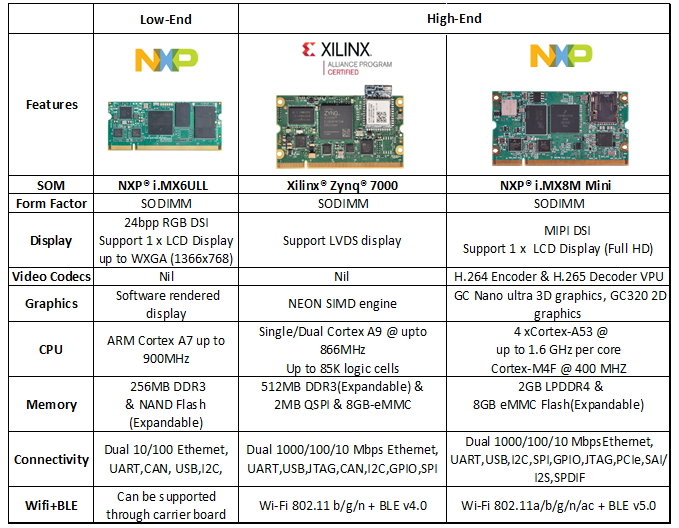
iWave’s System on Modules offers a highly efficient and feature-rich platform for enabling the development of smart, reliable and user-friendly HMI solutions. The SOMs support varying levels of GUI interface starting from entry-level low-resolution graphics to high performing 2D/3D GUI for enhanced user experience in the HMI interface. iWave’s high-end SOMs are capable of performing real-time communication with the EV Battery Management
System (BMS), collects vital data, perform analysis and enable remote access, real-time monitor and diagnosis of battery health and energy status. The SOMs supports platforms to enable secure customer authorization and payment and allows connectivity with Cloud platforms to generate advanced data analytics and diagnostics report for the consumers.
The SOMs integrates powerful ARM® Cortex® cores and comprises of all the essential interfaces, connectivity and graphics acceleration for enabling high performance, rugged and cost-effective HMI solutions.
The Zynq 7000 SOM incorporates a flexible ARM® + FPGA architecture that enables hardware, software and I/O programmability to satisfy various design requirements. The SOM allows the integration of custom I/O interfaces, serial ports, hardware acceleration, etc. to complement the addition of extra interfaces and features at the backend BMS and the HMI interface.
The SOMs and its key features for HMI applications are illustrated below:
iWave also offers ready to use custom and performance scalable HMI panels with various configuration options in terms of processor performance, memory, display /resolution, OS, GUI, driver development/porting, etc.
iWave’s vast experience in SOM ODM business with the added advantage of design service for Industrial, Automotive, Health Care and Embedded applications elevates us as a one-stop-shop for all hardware, software and customized design solutions.
With 10+ years of product availability, custom SOM configuration and dedicated technical support including carrier board review, software support, etc., designers and OEMs can be assured of our unwavering quality and long-term service. Our support resources include detailed hardware and software user manual, carrier board schematics, BSP package with toolchain support, reference designs, etc.,
For further information or inquiries please write to mktg@iwavesystems.com or contact our Regional Partners.
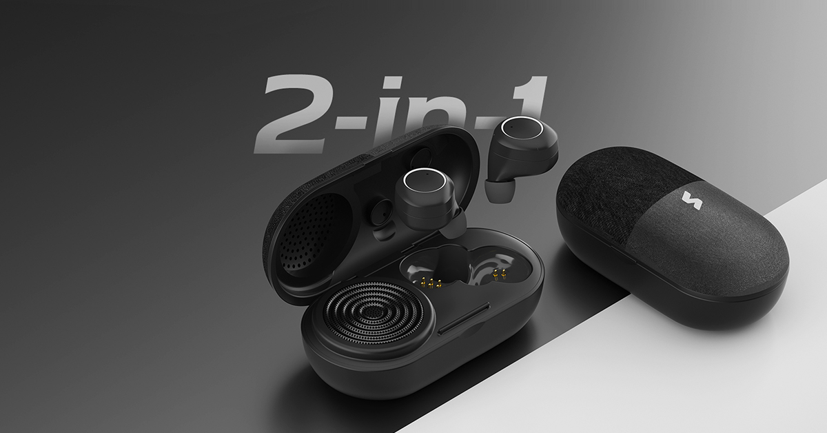
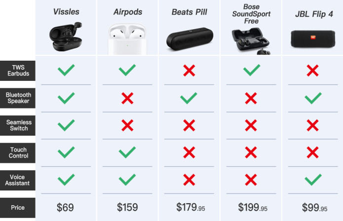
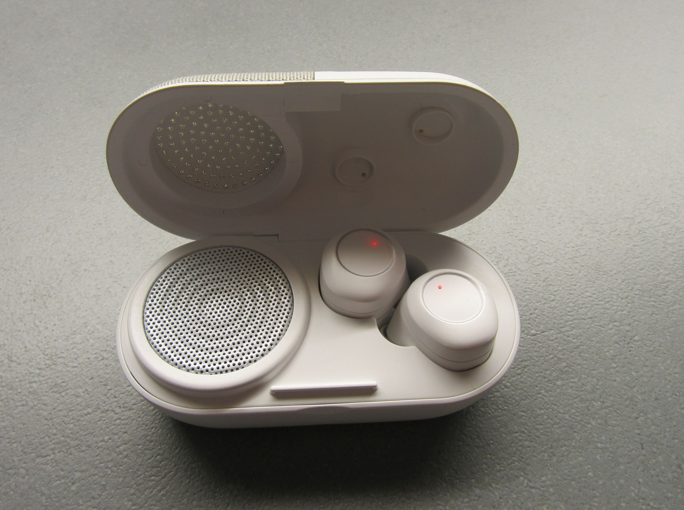
TWS Earbuds+BT Speaker+Charging Case| Palmsize|BT5.0 |Touch Control|Voice Assistant| IPX5 Waterproof, this is Vissles.
As digital devices and products continues to proliferate in our world, it can be a burden to add more and more accessories in our daily life. From smartphones to smart watches to home pods, etc., we are entering an era where having a device that serves two or more purposes is becoming a bliss. One of such situations where users have to deal with multiple devices is listening to music. People tend to have different devices for different music situations; earbuds for private music listening, Bluetooth speakers when in a meeting with friends, etc., but what if you could have one device do all of this? Serve as your earbuds and also a Bluetooth speaker for small gatherings? This was the question that led Vissles, an emerging brand of high-fidelity wireless audio devices, to develop their innovative 2-in-1 wireless earbuds that doubles as a powerful Bluetooth speaker.
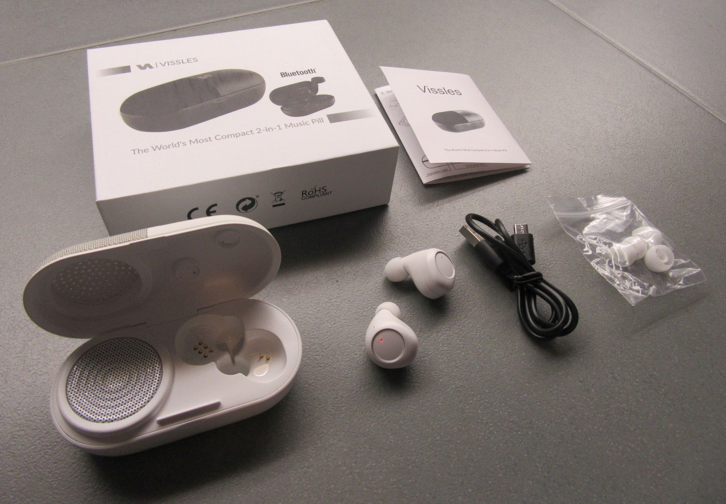
Vissles box contents
The product which is going to launch in October (indiegogo.com page), provides music lovers with the opportunity of experiencing the best of both worlds in a single device as it delivers a versatile way to listen to music alone or with a group.
Vissles seamlessly transforms from earbuds to sound hub to perfectly suit any listening situation. When used as earbuds, users get to enjoy a comfortable and compact pair of earbuds with an advanced Passive Noise Cancellation (PNC) design that delivers a noise-free and crystal-clear audio experience in challenging environment, pumping out flawless sound with strong bass, accurate mids, and crisp treble. In sound sharing mode, the storage and charging case doubles as a high fidelity Bluetooth speaker through which users can share their favorite playlists with friends and family anywhere. This demonstrates an high-level of innovative thinking as it is one of a kind and building some usefulness into the earbud’s case, definitely makes sense.
Vissles comparison with similar products
According to the company’s CEO, Vissles is always seeking a way to have more meaningful and convenient listening experiences. He said:
“ Our goal was to take versatility and convenience to the next level by combining the convenience of wireless earbuds with a powerful Bluetooth speaker so the device can seamlessly transform from earbuds for the individual, into a powerful Bluetooth speaker for the home and for sharing with friends”.
In addition to being the most versatile pair of digital audio devices for unparalleled sound quality, Vissles also add useful features like; intuitive touch controls for ease of use, and full voice assistant integration to access information with just a single tap. Vissels uses all of these, combined with low-energy consumption and a secure protocol to deliver stable connectivity and smooth audio transmission.
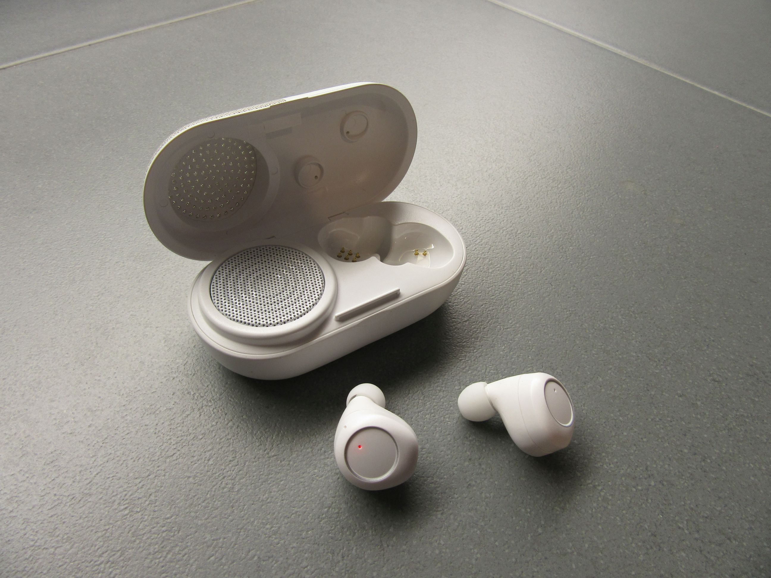
Vissles out of the box
The flexibility and immersive sound experience Vissles provides makes it excellent for sports, active lifestyles, and daily life as it sets a new standard for convenience and practicality for the busy nature of today’s users.
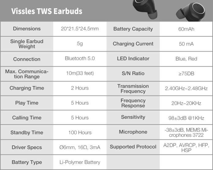
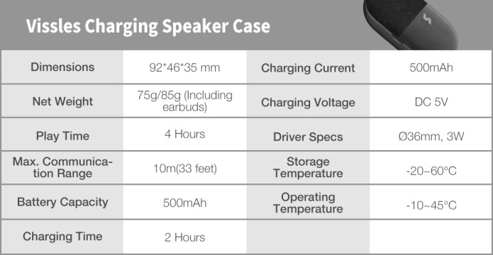
Specifications
Vissles is set for a launch in October and a pre-lauch page is published on Indiegogo.com along with some additional information. However, as long as the price is within the range of the combined cost of a pair of quality earbuds and a bluetooth speaker, I believe the 2-in-1 nature of Vissiles should be worth it. One less device to charge could actually translate to less complexity, less energy cost (hopefully), more space in backpacks, and more flexibility.
Playback time
One key feature I am looking out in Vissles is the battery life when used in speaker mode. The fully charged earbuds can continuously play for 5 hours. Used with the case, enjoy up to 4x the power for a total of 20+ hours of music! Simply put the earbuds back into the case and they will be automatically powered up. For the speaker, the fully charged case delivers 4+ hours of play time. Never let a dead battery ruin your gathering!
Unboxing Video
The campaign will last for a month. Users can grab one at the price of US$ 65 for the first 72 hours. After that, the price will increase a bit at US$69
You can get more information on Indiegogo.com page or www.vissles.com. Feel free to share your feedback regarding the campaign in the comments.
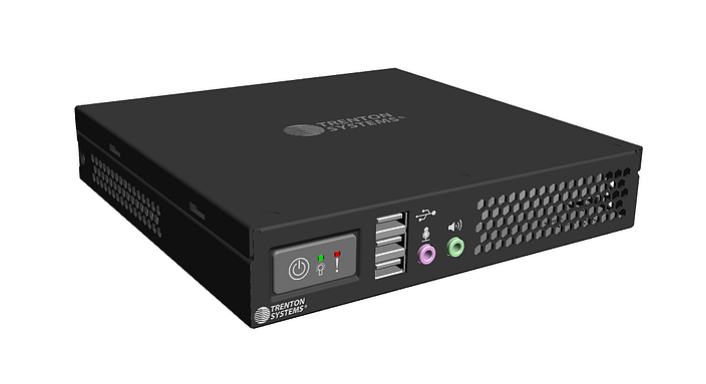
Trenton Systems is prepping a compact, Linux-friendly “Ion Mini PC” with 8th or 9th Gen Coffee Lake options and up to 32GB DDR4, SATA, DP, 6x USB 3.0, and 3x GbE, including one BMC-linked port for out-of-band, remote management.
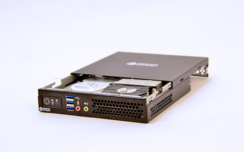
Trenton Systems has released a photo and preliminary documentation for an Ion Mini PC due to begin sampling by the end of the month. Although this Mini-ITX-based, 178 x 173 x 36mm system is a bit larger than what we typically consider to be a mini-PC these days, it packs in a lot of features including 6x USB 3.0 ports and a Gigabit Ethernet port linked to a Baseboard Management Controller (BMC) chip for remote, out-of-band management of network connections.
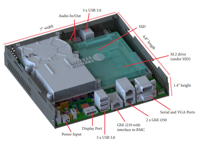
The Ion Mini PC supports up to 32GB of dual-channel DDR4-2400/2666, including ECC RAM. There’s an internal 2.5-inch SATA SSD drive and an M.2 slot (x4 PCIe) with NVMe storage support.
Other features include 6x USB 3.0 ports, a DisplayPort, and VGA and RS-2332 (DB9) ports. You also get include dual audio jacks, a power button and jack, and an LED.
The two standard Gigabit Ethernet ports use Intel i350 controllers while the BMC-linked GbE has an Intel i210. The port is monitored by an AST2500 Baseband Management Controller consisting of rKVM, system monitoring, out-of-band management, and a TPM 2.0 security chip. A customizable in-house BIOS is also available. The system supports 0 to 50°C temperatures with 5% – 90% non-condensing humidity tolerance.
The Ion Mini PC will begin sampling at the end of the month, with pricing undisclosed. More information should eventually appear on Trenton Systems’ website. Meanwhile, here’s the Ion Mini PC teaser page.
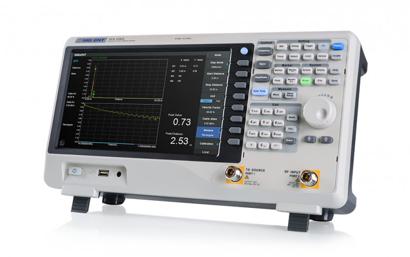
The SSA3000X-plus spectrum analyzer from Siglent Technologies combines the performance and reliability of the highly successful SSA3000X series with the features and ease of use of the SVA1000X series. By Nick Flaherty @ www.mwee.com
Siglent Technologies has launched a spectrum analyzer family that adds ease of use to its high performance platform.
The Spectrum & Vector Network Analyzer SVA1032X family is available with bandwidths from 9 kHz to 2.1 GHz. With the smallest resolution bandwidth (RBW) of 1 Hz, a noise level of
-161dBm can be displayed. Together with the amplitude accuracy of <0.7 dB, even the smallest signals just above the noise of the device can be detected and measured.
The “advanced measurements” option that combines the SSA3000X and AMK has also been extended with two additional measurements. In addition to the previous measurements of channel power (CP), adjacent channel power (ACPR), occupied bandwidth (OBW), TOI and waterfall diagram (monitor), the harmonic and carrier-to-noise ratio (CNR) measurements are now also implemented. The available EMC option offers EMI filter bandwidths of 200Hz, 9 kHz, 120 kHz and 1 MHz as well as the quasi-peak detector defined in CISPR.
In addition to the improvements and additions to the well-known functions, a completely new function has been added to the SSA3000X-plus. So, now there is a vector signal analysis option for analog and digital modulations (SSA3000X plus-AMA/DMA) available. This can be used, for example, to measure the error vector magnitude (EVM) of PSK, MSK or QAM modulated signals.
The 10.1-inch touch screen, the possibility to connect an external mouse & keyboard and the integrated web server make the operation easy and comfortable.
The starting price for the SSA3000X plus series is €1469.