Chirp for Arduino – Send Data Over the Air with Sound

With IoT expanding, developers are begining to desire more communication options to facilitate the exploration of diverse IoT possibilities. This was one of the reasons why the announcement of partnership between Chirp and Arduino was received with so much enthusiasm by the makers. Arduino has established itself as one of the biggest names in the ecosystem attached with its easy/ready to use hardware, while Chirp is arguably the most robust Data over Sound communication platform, as such, a lot of people believe the collaboration will not only bring Chirp’s  functionalities into Arduino but it will also make the corresponding functionalities easy to use. For today’s tutorial, we will look at how you can implement Chirp’s Data over Sound communication in your Arduino Project.

Data over sound is the process of converting information into audible or inaudible frequencies that get transmitted with a speaker and that can be received with the help of a microphone and Chirp is currently one of the best ways to do it. The Chirp SDK encodes the message you want to send into a series of sounds that form an audio barcode that can be played back with any device that has a loudspeaker. Devices that have a microphone can then listen for these codes and decode them to restore the original message.

Chirp adds a completely unique transport mechanism to Arduino boards. The added capabilities of data-over-sound means that makers have more connectivity options at their fingertips. Some of the advantages of data-over-sound include:

  • Device agnostic: data can be sent from mobile apps, web pages, or even with just an audio file
  • One to many: any device within hearing range is able to receive data in one simple transaction
  • Frictionless: doesn’t need any pairing, passwords or initial setup
Nano 33 BLE Sense

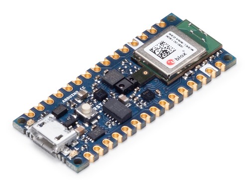
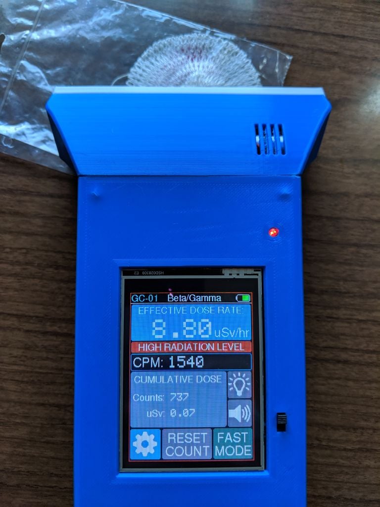
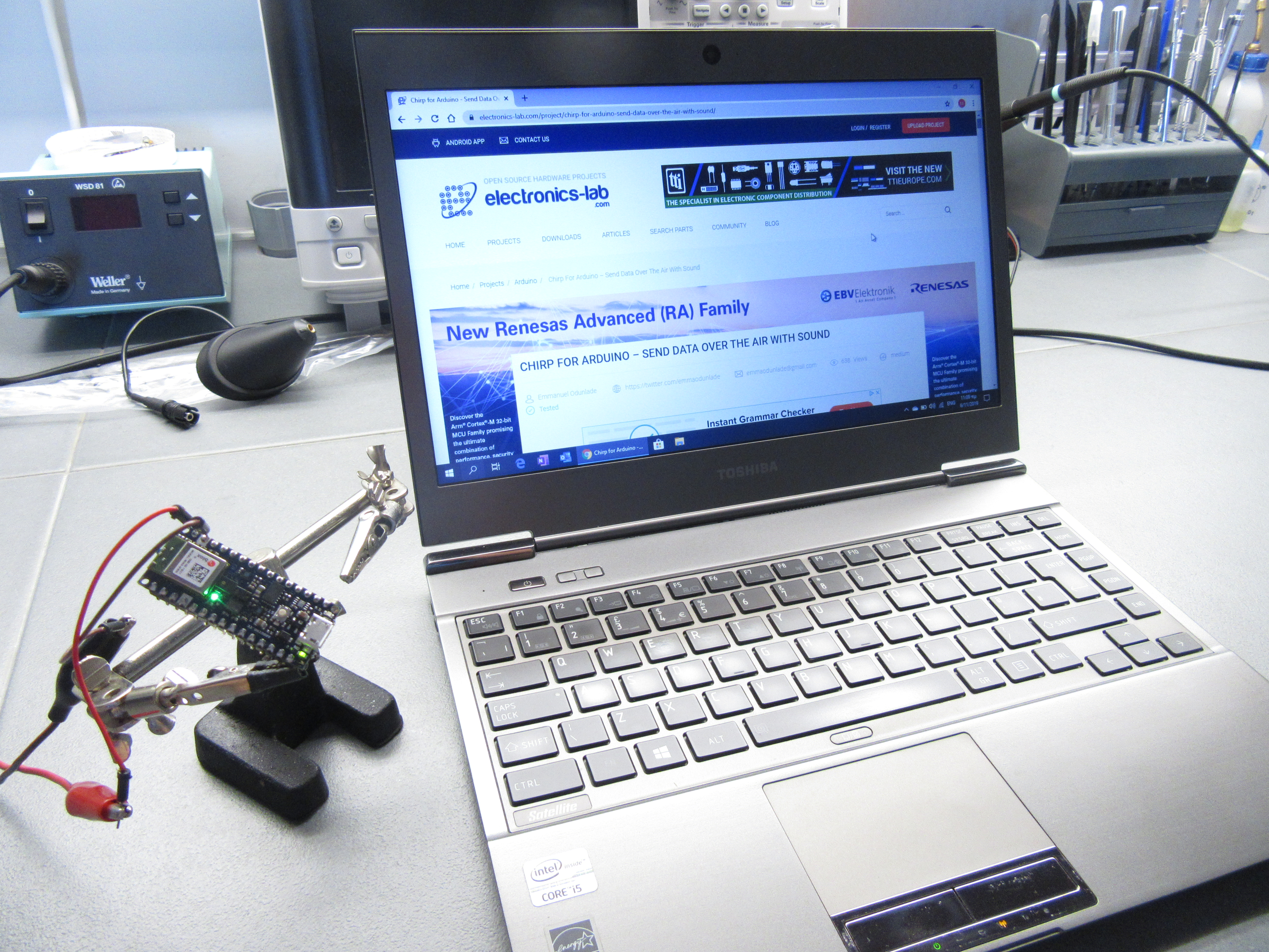
To demonstrate how to use Chirp features with the Arduino, we will build a simple project which changes the color of an attached LED in line with an RGB value received via audio signal. For this project, we will use the new Arduino “Nano 33 Sense” board which is one of the latest Arduino boards with a wide range of onboard sensors and features including an onboard microphone that is optimized for Chirp.

Required Components

Everything we need for this tutorial including the RGB LED, and Microphone, comes with the Nano 33 Sense board, making it the only thing needed for the tutorial. However, to be able to better observe the change in color, you may decide to use an external RGB LED asides the one onboard. To do that, you will need:

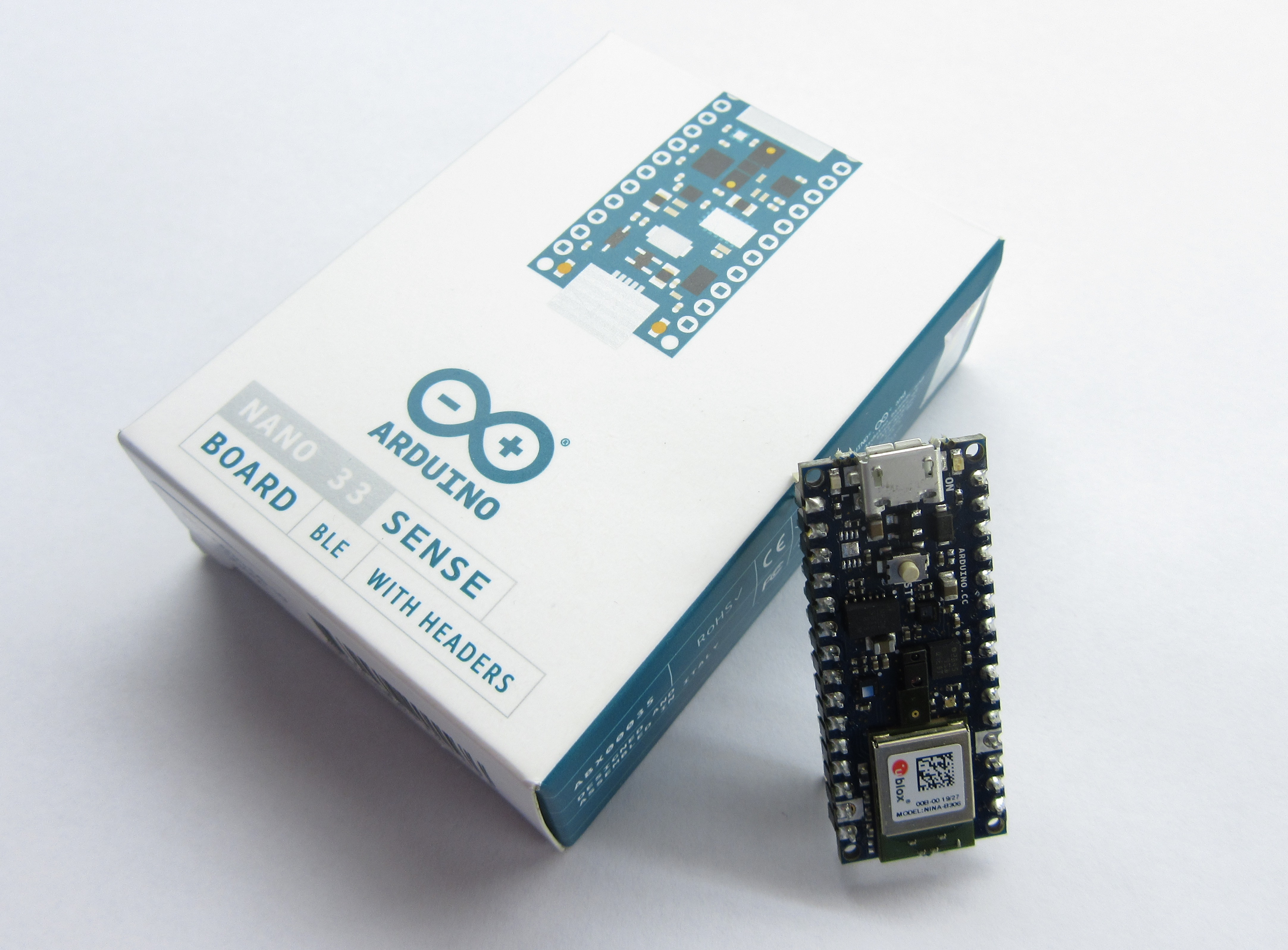
  1. The Nano 33 Sense Arduino Board
  2. 220 ohms Resistor
  3. RGB LED
  4. Breadboard
  5. Jumperwires
The Nano 33 Sense Arduino board can be bought from the official Arduino Store or from several other vendors on Ebay and similar platforms.
Nano 33 Sense Arduino board

Schematics

Going with the onboard RGB LED means you do not need to worry about schematics or connections as everything you need including the mic and the LED already comes with the board.

Getting Ready

Before we write the code for the project, we need to sign-up to Chirp to obtain the necessary credentials like the app key, the app secret and audio configuration as they will be required for our code.

Follow the steps below to complete your chirp sign up and obtain necessary details. If you have a Chirp account already, you can jump to step 3.

  1. Visit the Developers section of the Chirp website and click on the sign up button.
  2. On the resulting page, Choose the sign in with Google option or just fill in the details and hit the sign up button at the end of the page.
  3. With sign up complete, you will be automatically directed to a “configure your application” page. This page is  where you choose which of the Chirp protocol you will use for your project and the app key, secret and config will be automatically generated. Chirp currently supports 5 protocols with different audio transmission properties but for this tutorial, we will use the 16khz-mono-embedded protocol as it is the one currently supported for Arduino. Select it from the drop-down menu under the configuration section and click on the SAVE button.
  4. Your APP key, APP secret, and Configuration should now be generated. Copy them to a safe place as we will use them in the Arduino Sketch.

Another thing we need to do is to prepare the Arduino IDE by installing the Chirp SDK on it. Go to the Arduino Library manager (via Tools -> Manage Libraries) and enter “Chirp SDK” in the search bar. You will see the SDK listed as shown below.

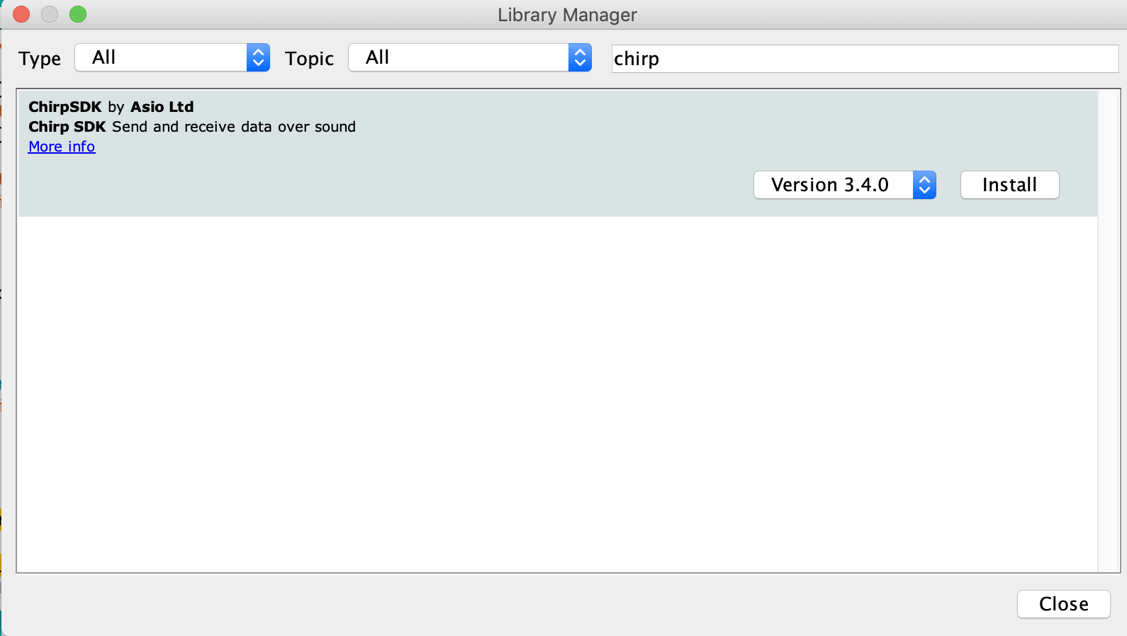
Click the install button and close the manager when done.

We are now ready to write the code for the project. However, ensure you are using the latest version of the IDE as older versions may not come with the Nano 33 Sense board installed although it can be installed via the IDE board manager.

Code

The code for this project is a modification of the receiver example attached to the Chirp SDK we installed earlier.

The thought process behind the code is simple. The devices stay on the lookout for audios matching that of its protocol. When the matching sound is received, it evaluates it and extracts the message stored in it. The message, which in this case is an RGB value, is then used to set the color of the connected (onboard) RGB LED.

Asides the Chirp SDK which we mentioned earlier, we will also use the PDM (Pulse Density Modulation) library. The PDM library will be installed when adding the Nano 33 Sense board via Boards Manager and makes it easy to work with PDM microphones like the MP34DT05 onboard the Nano 33 Sense.

As usual, I will do a brief explanation of the sketch, explaining sections I feel might be difficult to understand. We start the sketch by including these libraries mentioned above along with the Credentials.h file. The credentials.h file should be located in the same folder as your code. Ensure the chirp credentials we obtained earlier are filled accurately in it.

#include <PDM.h>
#include "chirp_sdk.h"
#include "credentials.h"

Next, we create variables to indicate the audio sampling rate, buffer size and pointers to the pins of the Nano 33 Sense in which the RGB LED is connected.

#define SAMPLE_RATE          16000
#define BUFFER_SIZE          256

#define R_LED_PIN            22
#define G_LED_PIN            23
#define B_LED_PIN            24

Next, we create an instance of the Chirp library along with global variables like sampleBuffer, and samplesRead.

static chirp_sdk_t *chirp = NULL;
short sampleBuffer[BUFFER_SIZE];
volatile int samplesRead;

Next, we create function definitions. Just to let the compiler know that we will be creating/using those functions later.

void setupChirp(void);
void chirpErrorHandler(chirp_sdk_error_code_t code);
void onPDMdata(void);

Next, we write the Void setup() function. We start the function by initializing the serial port so the serial monitor can be used for debugging. We follow that up by setting the pinMode of the three pins to which the RGB LED is connected as output.

void setup()
{
  Serial.begin(115200);
//  while (!Serial);

  pinMode(R_LED_PIN, OUTPUT);
  pinMode(G_LED_PIN, OUTPUT);
  pinMode(B_LED_PIN, OUTPUT);

Next, we enable the high-frequency oscillator on the board. This is done to ensure the clock is accurate across different boards.

// Enable high frequency oscillator
  NRF_CLOCK->EVENTS_HFCLKSTARTED = 0;
  NRF_CLOCK->TASKS_HFCLKSTART    = 1;
  while (NRF_CLOCK->EVENTS_HFCLKSTARTED == 0);

Next, we initialize Chirp communication by calling the setupChirp() function, initialize the PDM library by calling the onPDMdata() function whenever sound is received (PDM.onReceive()), and set the gain property of the microphone. The onPDMdata function is used to sample the received audio with the output stored in the samplesRead variable.

  setupChirp();

  PDM.onReceive(onPDMdata);
  PDM.setGain(30);

Next, the microphone is tested in such a way if the test fails, the code stays static in an unending while loop. This helps with debugging as it makes it easy to identify when the mic is bad.

if (!PDM.begin(1, SAMPLE_RATE))
{
  Serial.println("Failed to start PDM!");
  while (1);
}

Finally, we write maximum values to all the pins of the RGB LED and move to the void loop() function.

  analogWrite(R_LED_PIN, UINT8_MAX);
  analogWrite(G_LED_PIN, UINT8_MAX);
  analogWrite(B_LED_PIN, UINT8_MAX);
}

The void loop() function is quite simple. We run a check to see if samples have been read, if yes, the Chirp_connect_process_shorts_input() function is called to process the received audio and the response of the function is passed into the chirpErrorHandler() function. The samplesRead variable is then reset to zero.

void loop()
{
  if (samplesRead)
  {
    chirp_sdk_error_code_t err = chirp_sdk_process_shorts_input(chirp, sampleBuffer, samplesRead);
    chirpErrorHandler(err);
    samplesRead = 0;
  }
}

While the void loop() presents a very simple code structure, it is important to note that there are several functions associated with the commands within it. Some of those functions includes the setupChirp() which was called under the setup function and the onReceivedCallback() function.

The setupChirp() function is at the heart of the Chirp Data over Sound implementation. It takes in the app key and app secret obtained earlier and uses them to initialize Chirp communication. It also contains several callback sets which are used to determine what happens when a message is sent or in the sending process and when a message is received or being received. This call back makes it easy to perform actions and state what happens at every point during communication.

void setupChirp(void)
{
  chirp = new_chirp_sdk(CHIRP_APP_KEY, CHIRP_APP_SECRET);
  if (chirp == NULL)
  {
    Serial.println("Chirp initialisation failed.");
    return;
  }
  chirp_sdk_error_code_t err = chirp_sdk_set_config(chirp, CHIRP_APP_CONFIG);
  chirpErrorHandler(err);
  char *info = chirp_sdk_get_info(chirp);
  Serial.println(info);
  chirp_sdk_free(info);
  chirp_sdk_callback_set_t callback_set = {
    .on_state_changed = NULL,
    .on_sending = NULL,
    .on_sent = NULL,
    .on_receiving = onReceivingCallback,
    .on_received = onReceivedCallback
  };
  err = chirp_sdk_set_callbacks(chirp, callback_set);
  chirpErrorHandler(err);
  err = chirp_sdk_set_input_sample_rate(chirp, SAMPLE_RATE);
  chirpErrorHandler(err);
  err = chirp_sdk_set_frequency_correction(chirp, 1.00812);
  chirpErrorHandler(err);
  err = chirp_sdk_start(chirp);
  chirpErrorHandler(err);
  Serial.println("Chirp SDK initialised.");
  Serial.flush();
}

The onReceivedCallback function is the callback assigned to onReceived callback set in the setupChirp() function. It decodes the sound received and writes the values contained in it to the RGB LED pins.

void onReceivedCallback(void *chirp, uint8_t *payload, size_t length, uint8_t channel)
{
  if (length)
  {
    // High values mean lower brightness, so we
    // subtract from UINT8_MAX
    analogWrite(R_LED_PIN, UINT8_MAX - payload[0]);
    analogWrite(G_LED_PIN, UINT8_MAX - payload[1]);
    analogWrite(B_LED_PIN, UINT8_MAX - payload[2]);
  }
  else
  {
    analogWrite(R_LED_PIN, 0);
    analogWrite(G_LED_PIN, UINT8_MAX);
    analogWrite(B_LED_PIN, UINT8_MAX);

    delay(500);
    analogWrite(R_LED_PIN, UINT8_MAX);
    delay(500);

    analogWrite(R_LED_PIN, 0);
    Serial.println("Decode failed");
  }
}

Other functions used in the sketch include the onReceivingCallback() to flash the LEDs in a particular manner when data is being received and the chirpErrorHandler() which displays errors in human-readable formats.

void onReceivingCallback(void *chirp, uint8_t *payload, size_t length, uint8_t channel)
{
  Serial.println("Receiving data...");
  analogWrite(R_LED_PIN, UINT8_MAX);
  analogWrite(G_LED_PIN, UINT8_MAX);
  analogWrite(B_LED_PIN, UINT8_MAX);
}

void chirpErrorHandler(chirp_sdk_error_code_t code)
{
  if (code != CHIRP_SDK_OK)
  {
    const char *error_string = chirp_sdk_error_code_to_string(code);
    Serial.println(error_string);
    exit(42);
  }
}

The complete code for the project is available below and also attached under the downloads section below.

#include <PDM.h>

#include "chirp_sdk.h"
#include "credentials.h"

#define SAMPLE_RATE          16000
#define BUFFER_SIZE          256

#define R_LED_PIN            22
#define G_LED_PIN            23
#define B_LED_PIN            24


// Global variables ---------------------------------------------------

static chirp_sdk_t *chirp = NULL;
short sampleBuffer[BUFFER_SIZE];
volatile int samplesRead;


// Function definitions -----------------------------------------------

void setupChirp(void);
void chirpErrorHandler(chirp_sdk_error_code_t code);
void onPDMdata(void);

// Main ---------------------------------------------------------------

void setup()
{
  Serial.begin(115200);
//  while (!Serial);
  pinMode(R_LED_PIN, OUTPUT);
  pinMode(G_LED_PIN, OUTPUT);
  pinMode(B_LED_PIN, OUTPUT);

  // Enable high frequency oscillator
  NRF_CLOCK->EVENTS_HFCLKSTARTED = 0;
  NRF_CLOCK->TASKS_HFCLKSTART    = 1;
  while (NRF_CLOCK->EVENTS_HFCLKSTARTED == 0);

  
  setupChirp();

  PDM.onReceive(onPDMdata);
  PDM.setGain(30);

  if (!PDM.begin(1, SAMPLE_RATE))
  {
    Serial.println("Failed to start PDM!");
    while (1);
  }

  analogWrite(R_LED_PIN, UINT8_MAX);
  analogWrite(G_LED_PIN, UINT8_MAX);
  analogWrite(B_LED_PIN, UINT8_MAX);
}

void loop()
{
  if (samplesRead)
  {
    chirp_sdk_error_code_t err = chirp_sdk_process_shorts_input(chirp, sampleBuffer, samplesRead);
    chirpErrorHandler(err);
    samplesRead = 0;
  }
}


void onPDMdata()
{
  int bytesAvailable = PDM.available();
  PDM.read(sampleBuffer, bytesAvailable);
  samplesRead = bytesAvailable / sizeof(short);
}

// Chirp --------------------------------------------------------------

void onReceivingCallback(void *chirp, uint8_t *payload, size_t length, uint8_t channel)
{
  Serial.println("Receiving data...");
  analogWrite(R_LED_PIN, UINT8_MAX);
  analogWrite(G_LED_PIN, UINT8_MAX);
  analogWrite(B_LED_PIN, UINT8_MAX);
}

void onReceivedCallback(void *chirp, uint8_t *payload, size_t length, uint8_t channel)
{
  if (length)
  {
    // High values mean lower brightness, so we
    // subtract from UINT8_MAX
    analogWrite(R_LED_PIN, UINT8_MAX - payload[0]);
    analogWrite(G_LED_PIN, UINT8_MAX - payload[1]);
    analogWrite(B_LED_PIN, UINT8_MAX - payload[2]);
  }
  else
  {
    analogWrite(R_LED_PIN, 0);
    analogWrite(G_LED_PIN, UINT8_MAX);
    analogWrite(B_LED_PIN, UINT8_MAX);

    delay(500);
    analogWrite(R_LED_PIN, UINT8_MAX);
    delay(500);

    analogWrite(R_LED_PIN, 0);
    Serial.println("Decode failed");
  }
}

void chirpErrorHandler(chirp_sdk_error_code_t code)
{
  if (code != CHIRP_SDK_OK)
  {
    const char *error_string = chirp_sdk_error_code_to_string(code);
    Serial.println(error_string);
    exit(42);
  }
}

void setupChirp(void)
{
  chirp = new_chirp_sdk(CHIRP_APP_KEY, CHIRP_APP_SECRET);
  if (chirp == NULL)
  {
    Serial.println("Chirp initialisation failed.");
    return;
  }
  chirp_sdk_error_code_t err = chirp_sdk_set_config(chirp, CHIRP_APP_CONFIG);
  chirpErrorHandler(err);
  char *info = chirp_sdk_get_info(chirp);
  Serial.println(info);
  chirp_sdk_free(info);
  chirp_sdk_callback_set_t callback_set = {
    .on_state_changed = NULL,
    .on_sending = NULL,
    .on_sent = NULL,
    .on_receiving = onReceivingCallback,
    .on_received = onReceivedCallback
  };
  err = chirp_sdk_set_callbacks(chirp, callback_set);
  chirpErrorHandler(err);
  err = chirp_sdk_set_input_sample_rate(chirp, SAMPLE_RATE);
  chirpErrorHandler(err);
  err = chirp_sdk_set_frequency_correction(chirp, 1.00812);
  chirpErrorHandler(err);
  err = chirp_sdk_start(chirp);
  chirpErrorHandler(err);
  Serial.println("Chirp SDK initialised.");
  Serial.flush();
}


Demo

With the code complete, connect the Arduino Nano 33 Sense to your computer, select the board type and port, and hit the upload button.

To test the project, we will use the following prerecorded chirp files:

Red: Play this to change the color of the RGB to red.

Green: Play this to change the color of the RGB to Green.

Blue: Play this to change the color of the RGB to Blue.

Play any of these sounds within the audible range of the board and you will see the LED change to the color contained in the audio as shown below.

Chirp demo setup
Chirp demo setup

Instead of these prerecorded sounds provided by Chirp, you can decide to build another project which in place of the mic, will come with a speaker to broadcast the commands, so today’s project serves as the receiver. You can also develop your own sound command following the Audio API or play a random chirp from the applications page on the developers website.

Demo Video

Data over sound is one of the hottest research topics currently due to the possibilities it holds around redefining the way devices communicate. With breakthroughs like Chirp’s Ultrasonic protocols (which will hopefully come to Arduino soon), devices will be able to communicate using non-audible sounds. This means commands could be embedded in songs without the “weird” bird sounds and so on.

That’s it for this tutorial guys. Do reach out to me via the comment section if you have any questions or are facing any challenges with this project.

Resources used for this project are from Chirp’s documentation on the usage with Arduino. You can check it out to learn more.

Physicists demonstrate atomically-thin ultra-fast room temperature LED

Graduate researchers at the City College of New York have demonstrated a LED based on half-light half-matter quasiparticles in atomically thin materials. By Julien Happich @ eenewsled.com

This is also the first successful test of an electrically driven light emitter using atomically thin semiconductors embedded in a light trapping structure (optical cavity), the researchers claim in a paper titled “A room-temperature polariton light-emitting diode based on monolayer WS2“ published in Nature Nanotechnology.

While such LEDs have been realized in other materials at low temperatures, this device operates at room temperature and is fabricated using the now well known “scotch tape” based technique

Schematic of a half-light- half-matter quasiparticle based LED developed in Vinod Menon’s group using atomically thin materials. Image credit: Visakh Menon

“The fact that this device is fabricated using stacks of atomically thin materials and operates at room temperature makes it an important first step towards a technologically relevant device demonstration,” noted Vinod Menon, chair of physics in City College’s Division of Science and the research team’s mentor. “One potential application of such hybrid LEDs is the speed of operation which can translate to using them for LED based communication systems including LiFi”, Menon added.

The device was fabricated at the CCNY-based CUNY Advanced Science Research Center’s nanofabrication facility and tested in Menon’s lab. In follow- up research, the CCNY team is attempting to realize quantum emitters (single photon emitters) using a similar architecture.

City College of New York – https://www.ccny.cuny.edu

Xiaomi Wowstick Precision Mini Handheld Cordless Electric Screwdriver Review

Working on an electronics project or doing an electronics repair job is usually tedious and one of the contributing factors to this is the usual lack of the right tools for the necessary tasks including screwing and unscrewing parts. One approach to solve this problem was the development of electric screwdrivers and quite a lot of them exist in the market with different form factors to ensure the burden of electronics repair, has nothing to do with screws. However, most of these electric screwdrivers lack in the form factor and portability, as they are usually plugged-in (must be used around a socket), bulky and come with designs that don’t really facilitate the screwing action. Those reasons and more was what Xiaomi hoped to change with the development of the Xiaomi WOWStick Dual Power Precision Screwdrivers and especially with the Wowstick 1f+, being one of their latest versions.

Released in May 2018, the Wowstick 1f+ is a rechargeable electric screwdriver which comes in a Slim S2 aluminum alloy housing with an intuitive pen shape design, and a host of screw-bits (52) to ensure its probably the only screw driver you will ever need. It is driven by a flexible circuit design that allows it to run continuously for 8hours using 2 x AAA batteries.

It is equipped with a magnetic end which holds on to screw after they have been loosed, and it comes with a Piano-feel buttons strategically placed on the side, in a way that is easy for your thumb to press it for either screwing or unscrewing operations.

Introduction Video

Some of the highlighted features of the screwdriver includes:

  • Electric
  • Wireless/cordless
  • Multitude of different screw-bits/tips (up to 56!)
  • Interesting accessories like Magnetic Mini-tray
  • Charging via USB
  • Familiar Pen form factor
  • Integrated Leds
  • Idle speed: 200 rpm
  • Electric torque: Max 0.15 Nm (1.5 kg)
  • Charging Time: 40 min
  • Vacuum autonomy: 2h
  • Dimensions: 173 x 15.8 x 15.8 mm
  • Auto self-locking ratchet wheel orientation

The efficient nature and easy handling of the screwdriver makes it an ideal tool in the repair of delicate electronics gadgets, like mobile phones, but it may not be as much effective for use in heavy duty applications as it’s power is limited.

A quality, high-class, screw driver without a screw-bit is like a drill without a drill-bit. This is where the Wowstick screw-bit by Xiaomi for precision electric screwdrivers comes in. It is a 56 different bits made from S2 steel alloy with strong wear resistance and high hardness. Measuring 18.50 x 6.50 x 2.50 cm (or 7.28 x 2.56 x 0.98 inches) with a packaging weight of 0.2170 kg, the Wowstick 4mm multiple bit screws was designed to meet most daily repair needs from light-duty projects to bigger ones. The screw-bits are shipped with/or without the Wowstick screwdrivers (depending on the order), indicating that they fit to the Wowstick series of screwdrivers. They are also sold separately as they are compatible with other great brands of screwdrivers.

Unboxing Video

The screw bits come in various point-head types – the Torx, the Phillips, the Square, the Slotted, Y-type, Triangle, the Pentalobe – which make them perfect for fixing watches, phones, laptops, eyeglasses, precision apparatus, pieces of jewelry, as well as other small appliances. These bits have the power to unscrew even the tiniest and toughest screws and because they are particularly long, its quite easy to get them into tight spaces. One beautiful thing about these bits is that they are magnetized so they will help hold the screws. The magnetic quality for the bits is strong so you wouldn’t need to worry about dropping a screw and losing it.

the compatible Wowstick bits

The 56 pieces screw bits packaged in three sets are to be used with a Wowstick battery-powered screwdriver tool. Each set of the screw bits comes in a clear hard case; the screwdriver tool on one side and the different bits on the other side. The screwdriver tool has a simple nice design with overall metal construction and a rocker button for forward and reverses screw directions.

The packaged set of screw bits include:

  • Set X0 (comes with the screwdriver)
  • Set X1 (purchased separately)
  • Set X2 (purchased separately)
  • Set X3 (purchased separately)

Set X1

Set X1 contains 20 different point-type screw bits which include– the Hex: H0.7, H0.9, H1.3, H1.5, H2.0, H2.5,and H3.0, the slotted: SL1.0, SL1.5, SL2.0, SL2.5, SL3.0, SL3.5, SL4.0, the Phillips: PH0000, PH000, PH00, PH0, PH1 and PH2

Set X2

Set X2 is another set of 20pcs screw bits of various point type including – the Torx: T2, T3, T4, T5, T6, T7, T8, T9, T10, T15, T20, the Hex: H4.0, Y-type: Y0.6, Y1, Y2.0, Y2.5, Y3.0 and the Pentalobe: P2, P5 and P6.

Set X3

Set X3 come with 16pcs screw bits which includes, the Square bits: S0, S1, S2, W: 1.5, Needle bits: 0.8, Triangle bits: 2.0, 2.3, 2.5, 3.0, U-Type: U2.0, U2.6, U3.0 and extended 45mm bits: PH0, PH2, SL2.0, and H2.0.

To install the bits on the tool, just insert the drivers into the rubber end of the tool and you are ready to control it with the forward and reverse button. Without having to use a more powerful cordless or corded drill, there is much ease in screwing and unscrewing the screws and other fasteners.

You can buy Xiaomi WOWStick and Wowstick screw-bit by Xiaomi from Gearbest for 15.55€ and 10.6€ respectively. The Xiaomi WOWStick with coupon “GBAFF081212” the price will be $13.99

Intrinsyc Announces New Premium-Tier System on Module based on Qualcomm Technologies’ SDA845 System on Chip

Designed for use in Advanced Robotics and Drones, Premium Camera Applications, Artificial Intelligence Platforms, and other Cutting-edge IoT Devices.

Intrinsyc Technologies Corporation, a leading provider of solutions for the development and production of embedded and Internet of Things (IoT) products, today announced the Open-Q™ 845 µSOM (micro System on Module) and Development Kit, to be available in the fourth quarter of 2019.

The Open-Q™ 845 µSOM is the latest product in the evolution of Intrinsyc’s µSOM computing module series. It is an ultra-compact (50mm x 25mm), production-ready embedded module, ideal for powering the most advanced robotics, drones, cameras, and embedded IoT devices requiring the latest on-device AI powers. Featuring the Qualcomm® SDA845 system on chip (SoC) from Qualcomm Technologies, Inc., the 845 µSOM integrates many new features and capabilities in the same small form-factor:

  • Higher performing Octa-core CPU – up to 2.6GHz on Gold cores
  • New hardware-based security layers for vault-like defense
  • Third generation Qualcomm® AI platform for immersive, on-device intelligence
  • Four camera ports with flexible configurations supports up to 7 cameras
  • New camera architecture for cinema grade video capture
  • DisplayPort 4K60 via USB Type-C with USB super-speed data concurrency
  • Additional USB3.1 port for device connectivity while using DisplayPort
  • Gen3 PCIe interface.

This powerful new hardware platform will be supported by your choice of full-featured Android 9 or Yocto Linux operating systems, with plans for offering Android 10 by Q2 next year. The Android 9 operating system will be shipped on the development kit and is an ideal starting point for evaluation of the SOM and to kick-start your product development. If you prefer a Linux OS, that will be available to download from Intrinsyc and program onto your development kit. Full software documentation will also be included with purchase of the development kit.

“We are excited to introduce this premium performance IoT computing module featuring; ultra-fast computational power, support for variety of AI frameworks, advanced video and image processing capabilities, an integrated secure processing unit, and other trailblazing features,” said Cliff Morton, Vice President, Solutions Engineering, Intrinsyc.  “We will launch our development kit and SOM in the fourth quarter, 2019 and already have clients developing products with plans for commercial product launch in the first quarter,  2020.” 

Intrinsyc is a leader in developing embedded solutions for IoT products, and we’re excited to see them offer a premium-tier system to provide cutting-edge embedded solutions for drones, robots, and other applications using our Qualcomm SDA845 chipsets,” said Dev Singh, director, business development and head of robotics, drones, and intelligent machines, Qualcomm Technologies, Inc.

Open-Q™ 845 µSOM Key Specifications:

  • Qualcomm® SDA845 SoC built on 2nd-Gen 10nm technology:
    • Qualcomm® Kryo™ 385 Octa-core CPU
    • Qualcomm® Adreno™ 630 Visual Processing Subsystem
    • Qualcomm Spectra™ 280 Image Signal Processor
    • Qualcomm® Hexagon™ 685 DSP
    • Qualcomm® Secure Processing Unit
    • Third Generation Qualcomm® Artificial Intelligence Engine for on-device intelligence
  • System Memory: 4GB or 6GB LPDDR4x RAM (POP) + 32GB or 64GB UFS flash storage
  • Wireless Connectivity: Wi-Fi 802.11a/b/g/n/ac 2.4/5Ghz 2×2 MU-MIMO + Bluetooth 5.x
  • Display Interfaces:
    • DisplayPort v1.4 on USB Type-C, up to 4K60 with USB data concurrency
    • 2x MIPI 4-lane DSI up to 4K 10-bit 60fps
  • Camera Interfaces:
    • 4 Cameras: 3x 4-lane MIPI CSI + 1x 2-lane MIPI CSI camera ports
    • Dual 16MP ISP + ISP-lite 2MP
  • Video Performance:
    • Encode: 4K60 H.264/H.265, 4K30 for VP8
    • Decode: 4K60 H.264/H.265/VP9
  • Audio Interfaces:
    • Dedicated Audio DSP supporting Qualcomm® WCD9340 audio codec (off-SOM)
    • SLIMBus or multi-channel I2S digital audio interfaces
  • I/O Interfaces:
    • 2x USB3.1, one with Type-C/DisplayPort support
    • 1x USB2.0 micro-B debug UART
    • 1x SDIO 4-bit interface
    • 1x PCIe Gen3 1-lane interface
  • Power: Integrated power and battery management on SOM
  • Size: 25mm x 50mm
  • Operating System: Android 9, Linux

For additional information and to register for updates on availability go to: https://www.intrinsyc.com/open-q-845-usom/

To help IoT device makers accelerate time to market, Intrinsyc offers the Open-Q™ 845 µSOM Development Kit, a full-featured platform including software tools, documentation, and optional accessories – everything required to immediately begin evaluation and product development. The development kit marries the production-ready Open‐Q™ 845 µSOM with a carrier board providing numerous expansion and connectivity options to support development and testing of peripherals and applications. The development kit, along with the available documentation, also provides a functional reference design for your own custom carrier board. This will provide a low-risk, fast track to market for your latest new product.

More information on the development kit is available at: https://www.intrinsyc.com/open-q-845-usom-development-kit/

In addition to production-ready SOMs, development platforms, and tools, Intrinsyc offers turnkey product development services, driver and application software development, and technical support. Contact Intrinsyc at https://www.intrinsyc.com/sales-inquiry/ with your product requirements and have one of the Company’s solution architects help plan your successful product development and launch.

Toradex announces its Apalis SoM based on the NXP i.MX 8QuadMax applications processor

Toradex, a leader in embedded computing, announced today general availability for its Apalis System on Module (SoM) based on the NXP® i.MX 8QuadMax applications processor. The SoM has been available as part of Toradex’s ‘early access’ program to its key partners and customers for several months and has a minimum product availability until 2030.

The SoM is pin-compatible with the Apalis family, including i.MX 6 and NVIDIA®-based SoMs. This allows Apalis-based products to be easily scaled. All Toradex software and support resources are available, including a high-quality Yocto Project-based Linux BSP and the new upcoming easy-to-use Industrial Linux Platform Torizon. Operating Systems provided by partners include Android from KyneticsQNX, and Greenhills INTEGRITY.

The NXP i.MX 8QM SoC is the highest performance variation of the i.MX 8 family, featuring 6x Armv8-A 64-bit processor cores – 2x Arm Cortex-A72 & 4x Cortex-A53 – as well as 2x additional Cortex-M4F microcontrollers. The integrated HIFI4 DSP, a high-performance dual GPU, 28 nm FD-SOI technology for decrease in soft error rates, and extra safety features are other highlights.

With this, you can leverage the Toradex Partner Ecosystem. Here are some highlights:

“The high performance and rich feature set of the NXP i.MX 8QuadMax makes the part very attractive to a wide range of markets from Automotive to Industrial and IoT”, said Patrick Stilwell, Product Marketing Manager for the NXP i.MX 8 Family, NXP Semiconductors. “Partnering with leaders in the embedded board market such as Toradex enables NXP to serve a wider range of customers and help them get to market faster.” he added.

Highlights

  • Up to 2x Arm® Cortex-A72, 4x Cortex-A53, 2x Cortex-M4F
  • NXP® i.MX 8QuadMax (i.MX 8QM), i.MX 8QuadPlus (i.MX 8QP)
  • Latest Armv8 64-Bit CPU cores
  • On-board dual-band 802.11ac 2×2 MU-MIMO Wi-Fi and Bluetooth 5
  • Multiple OS deployment with heterogeneous multi-core architecture
  • Advanced hardware security and safety features
  • Ideal for signal processing, computer vision, and HMI applications

“The next generation of the Rimac Infotainment system, introduced with our all-electric Rimac C_Two hypercar, will feature a multi-screen consolidated cockpit based on the Toradex Apalis i.MX 8QuadMax SoM. The powerful A72 and A53 cores will allow us to provide rich graphics and a comprehensive multimedia experience, while the M4 cores, along with the capability of software domain separation will allow us to develop ASIL-B compliant solutions for our vehicles as well as for other OEMs.
Our long term cooperation with Toradex has allowed us to develop a comprehensive and flexible code base that can easily be upgraded from the previous Apalis i.MX6 based infotainment to the new i.MX8 based one” said Tomislav Lugarić, ICU Software Manager, Rimac Automobili d.o.o.

More information about the SoM is available here: https://www.toradex.com/computer-on-modules/apalis-arm-family/nxp-imx-8

Upcoming Webinar: Join our upcoming webinar with NXP on Nov 7, 2019, entitled ‘Develop faster with the i.MX 8QuadMax processor‘. Register here.

Arduino MKR 20×4 I2C OLED shield

20×4 character alphanumeric I2C OLED shield for Arduino MKR series. It provides high quality OLED screen to the newest Arduino platform. With 3.3V operation you can power your project from lithium battery. This is a bright and wide temperature range OLED that works below freezing, making it useful for outdoor applications.

  • Dimensions: 65 mm x 25 mm x 13.5 mm.
  • Working voltage: 3.3V from Arduino
  • Temperature range: -40°C to +80°C
  • Interface: I2C + Reset line
  • Controller: SSD1311

This product comes as a soldered MKR shield ready to use. Pictures are for illustration, only the assembled OLED shield will be shipped, Arduino MKR in the pictures is not included.

This shield uses EA OLEDM204-LGA display from Electronic Assembly.

Microchip simplifies hardware-based IoT security

A pre-provisioned solution that provides secure key storage for low-, mid- and high-volume device deployments using the ATECC608A secure element is now available from Microchip Technology. According to the company, the Trust Platform for its CryptoAuthentication family enables companies of all sizes to implement secure authentication.

The platform consists of a three-tier offering, providing out-of-the-box pre-provisioned, pre-configured or fully customisable secure elements, allowing developers to choose the platform best suited for their individual design. As the first solution to provide ready-to-go secure authentication for the mass market, the first tier – Trust&GO – provides zero-touch pre-provisioned secure elements with a minimum orderable quantity (MOQ) as low as 10 units.

Device credentials are pre-programmed, shipped and locked inside the ATECC608A for automated cloud or LoRaWAN authentication onboarding. In parallel, corresponding certificates and public keys are delivered in a “manifest” file, which is downloadable via Microchip’s purchasing e-commerce store and select distribution partners.

With the ability to authenticate to any public or private cloud infrastructure, Microchip’s Trust Platform is also flexible and customisable. For customers who want more customisation, the program includes the TrustFlex and TrustCustom platforms.

The solution helps simplify provisioning logistics, says the company, making it easy for mass market customers to secure and manage edge devices without the overhead cost of third-party provisioning services or certificate authorities.

The second tier in the program, TrustFlex, offers the flexibility to use the customer’s certificate authority of choice while still benefiting from pre-configured use cases.

These use cases include baseline security measures such as transport layer security (TLS) hardened authentication for connecting to any IP-based network using any certificate chain, LoRaWAN authentication, secure boot, Over-the-Air (OTA) updates, IP protection, user data protection and key rotation. This can reduce the time and complexity involved in customising the device without requiring customised part numbers.

For customers who would like to customise their designs entirely, the third tier in the program – TrustCustom – provides customer-specific configuration capabilities and custom credential provisioning.

www.microchip.com

New MKR WAN 1310 for LoRa connectivity comes with 2MByte Flash and extended battery life

Arduino announced the launch of the Arduino MKR WAN 1310, which offers a practical and cost-effective solution for those looking to add LoRa connectivity to their projects. 

The new MKR WAN 1310 enables you to connect your sensors and actuators over long distances harnessing the power of the LoRa wireless protocol or throughout LoRaWAN networks.

This open source board can be connected to:

  • Arduino Create
  • Your own LoRa network using the Arduino Pro Gateway for LoRa
  • Existing LoRaWAN infrastructure like The Things Network
  • Or even other boards using the direct connectivity mode

The latest low-power architecture has considerably improved the battery life on the MKR WAN 1310. When properly configured, the power consumption is now as low as 104uA!  It is also possible to use the USB port to supply power (5V) to the board; run the board with or without batteries – the choice is yours.

Based on the Microchip SAM D21 low-power processor and a Murata CMWX1ZZABZ LoRa module, the MKR WAN 1310 comes complete with an ECC508 crypto chip, a battery charger and 2MByte SPI Flash, as well as improved control of the board’s power consumption.

Data logging and other OTA (Over-the-Air) functions are now possible since the inclusion of the on board 2MByte Flash. This new exciting feature will let you transfer configuration files from the infrastructure onto the board, create your own scripting commands, or simply store data locally to send it whenever the connectivity is best. While the MKR WAN 1310’s crypto chip adds further security by storing credentials and certificates in the embedded secure element.

Specifications:

  • MCU – Microchip Atmel SAMD21 32-bit ARM Cortex M0+ MCU @ 48 MHz with 32 KB SRAM, 256 KB flash (8KB for bootloader)
  • External Storage – 2MB SPI flash
  • Digital I/O Pins – 8x digital I/Os, 12x PWM, UART, SPI, and I2C, 8x external interrupts
  • Analog Pins – 7x analog inputs (8/10/12-bit ADC), and 1x analog output (10-bit DAC)
  • DC Current per I/O Pin – 7 mA
  • LPWAN connectivity
    • Murata CMWZ1ZZABZ LoRa module based on Semtech SX1276 and STMicro STM32L
    • Antenna power – 2dB
    • Carrier frequency – 433/868/915 MHz
    • Working regions – EU/US
  • USB – 1x micro USB port for power and programming
  • Security – ATECC508 secure element (ECC508 crypto chip)
  • Misc – Reset button, 6x LEDs, 32.768 kHz RTC
  • Power
    • 5V via micro USB port or VIN pin
    • 2-pin header for rechargeable Li-ion or Li-Po battery
    • I/O Operating Voltage – 3.3V
  • Power Consumption – As low as 104uA
  • Dimensions – 67.64 x 25 mm
  • Weight – 32 grams

These features make it the perfect IoT node and building block for low-power wide area IoT devices.

The MKR WAN 1310 is available on the Arduino Store, where you’ll find complete specs and more information.

DIY Geiger Counter With an ESP8266 and a Touchscreen

Several of our past tutorials looked at the possibility of building the hobbyist version of several important tools and equipment used by different categories of makers. We have explored how to build the DIY/Hobbyist versions of seemingly easy tools like a voltmeter to more complex and abstract tools like the VU meter, but for today’s tutorial, we will work on the development of a very important tool in the history of technology; the Geiger Counter.

The Geiger counter is an instrument used for detecting and measuring ionizing radiation. It is one of the worlds best-known radiation detection instrument as it can be used to detect ionizing radiation such as alpha particles, beta particles, and gamma rays and its is usually used as a handheld radiation survey instrument, warning its users when in the region of dangerous ambient radiation levels with an all-too-familiar clicking noise. The counter detects ionizing radiation through the use of the ionization effect produced in a Geiger Muller tube which, you guessed right, is probably why it is named after the German Physicist.

While there are many DIY attempts at the Geiger-counter field on the internet, today’s tutorial will show the efforts of “Instructable” user Prabhat who combined an ESP8266 with a touchscreen display to create a unique device with a custom GUI through which the information is displayed in a very user-friendly way.

The principle of operation of a Geiger Counter is simple. A thin-walled tube with a low-pressure gas inside (called a Geiger-Muller Tube) is energized with a high voltage across its two electrodes. The electric field that’s created is not enough to cause dielectric breakdown – so no current flows through the tube. That is until a particle or photon of ionizing radiation goes through it. As such, when a beta or gamma radiation passes through, it can ionize some of the gas molecules inside, creating free electrons and positive ions. These particles start moving due to the presence of the electric field, and the electrons actually pick up enough speed that they end up ionizing other molecules, creating a cascade of charged particles which momentarily conduct electricity. This brief pulse of current can be detected using the connected electronic circuit and then be used to create the clicking sound, or in this case, fed to the microcontroller to perform calculations and display readings.

SBM-20 GM Tube

This project is built around the SBM-20 Geiger tube since it is quite easy to find it on eBay, and very sensitive to beta and gamma radiation.
At the end of this tutorial, you would have acquired the capacity to develop your own Geiger counter and the confidence to build more DIY based tools.

Required Components

The following components are required to build this project;

The components can be bought from online electronics component sales stores like Aliexpress and even eBay or directly via the attached links.

Schematics

While the project can be implemented on a breadboard, to reduce the complexity involved and ensure things fit nicely in the enclosure, a PCB was designed for the project. As a result of this, the schematics for this project won’t be in the usual Fritzing breadboard style but the connections will still be clear and easy to follow. The components are connected as shown in the schematics below.

Schematics

So, you can choose to either produce your own PCB or just replicate the schematics on a breadboard or VeroBoard.

High Voltages appear on circuit when powered. Please don’t touch it while under power!

The PCB design files are attached along with other files (Gerber) under the download section. A picture of the schematics implemented on a PCB is shown below.

For those who would like to replicate the project on a breadboard, below is an image showing how the project looks when implemented on a breadboard.

Breadboard Implementation

Enclosure Design

This project is one of those that deserves going an extra mile, this is why to make the project look neat and give it an appealing finish, an enclosure was designed to improve not just the physical look of the device but also the functional parts.


The enclosure was designed with flexibility in mind. It was broken down into different parts which can all be joined together with M3 countersunk screws except for the “sensor housing” which will need to be glued or “welded” (by melting with a soldering iron) to the “case top” part.

The standoffs help keep the PCB (which is 120 x 75 mm) securely attached to the front of the case and can be optionally glued to the underside of the cover for easier assembly and disassembly.

Four standoffs will be required for the full assembly. The .STL files of all parts of the enclosure are attached under the download section and can also be found on Thingiverse.

Code

With your breadboard or PCB version of the device ready, we can now upload code to it.

We will use Platform.io to program the ESP8266 and this requires quite some work to set it up. So if this is your first time using the ESP8266, you will need to go through the process of installing the ESP8266 board support on the Arduino IDE and also setting up Platform.io on VScode for writing Arduino codes. You can check out our articles in the links attached.

The sketch for this project is heavily reliant on the Adafruit_ILI9341 and Adafruit GFX library. The ILI9341 library allows us to directly interact with the display as it was used to create the user interface for the display. We will create two major UIs; One will be the homepage while the other will be a settings menu.  The home page will show important information like the dose rate, counts per minute, and the total accumulated dose since the device was turned on while the settings menu, on the other hand, will allow users to set things like the dose units, the alert threshold, and the calibration factor that relates the CPM to dose rate. All of the settings are saved on the microcontrollers EEPROM ensuring the data is not lost when the device is disconnected from power.

To help us access the EEPROM we will use the EEPROM library created for the ESP8266. It is one of the libraries that are automatically installed when you add the ESP8266 board reference to your Arduino IDE.

The code for today’s project is quite long but, as usual, I will do a run through to explain some of the very important and tricky parts. Ensure all the libraries mentioned above are installed on the Arduino IDE, then launch VSCode and create a new project. Open the main.cpp file and start typing in your code.

We start the sketch by including all the libraries required for the project. By default the Arduino.h library will be added by platform.io if not, go ahead and add it. Add the other libraries too as shown below.

#include <Arduino.h>
#include <ESP8266WiFi.h>
#include <EEPROM.h>
#include "SPI.h"
#include "Adafruit_GFX.h"
#include <Fonts/FreeSans9pt7b.h>
#include <Fonts/FreeSans12pt7b.h>
#include "Adafruit_ILI9341.h"
#include <XPT2046_Touchscreen.h>

The ESP8266WiFI library was only added to enable us to disable the WiFi so as to reduce power consumption while the SPI library is what allows us to talk to the display since it’s connected to the ESP over SPI. The XPT2046_Touchscreen.h library allows us to use the touchscreen feature of the display.

Next, we create an object of the touchscreen library with the CS pin as an argument and then create variables to hold the (4 extremes) calibration points for the touch screen and specify the pins of the Arduino to which the DC and CS pins of the display are connected.

#define CS_PIN D2
XPT2046_Touchscreen ts(CS_PIN);

#define TS_MINX 250
#define TS_MINY 200 // calibration points for touchscreen
#define TS_MAXX 3800
#define TS_MAXY 3750

#define TFT_DC D4
#define TFT_CS D8

We also create variables to hold the hex values signifying the different colors that we will be using after which we create an instance of the Adafruit TFT library and create several other variables used to hold different values in the code.

#define BLACK 0x0000
#define BLUE 0x001F
#define RED 0xF800
#define GREEN 0x07E0
#define CYAN 0x07FF
#define MAGENTA 0xF81F
#define YELLOW 0xFFE0
#define WHITE 0xFFFF
#define DOSEBACKGROUND 0x0455

Adafruit_ILI9341 tft = Adafruit_ILI9341(TFT_CS, TFT_DC);

Notably we also create variables settingsBitmap, ledOnBitmap, ledOffBitmap, and backBitmap which are used to hold the Char equivalent of a bitmap image. We covered how to generate this in a previous tutorial we did on displaying bitmap images on LCDs.

const unsigned char settingsBitmap[] PROGMEM = {
    0x00, 0x00, 0x00, 0x00, 0x00, 0x00, 0x00, 0x00, 0x00, 0x00, 0x00, 0x00, 0x00, 0x00, 0x00, 0x00,
    0x00, 0x00, 0x00, 0x00, 0x00, 0x00, 0x00, 0x00, 0x00, 0x00, 0x00, 0x00, 0x00, 0x00, 0x00, 0x00,
    0x00, 0x00, 0x00, 0x00, 0x00, 0x00, 0x00, 0x00, 0x00, 0x00, 0x00, 0x00, 0x00, 0x00, 0x00, 0x00,
    0x00, 0x00, 0x00, 0x00, 0x00, 0x00, 0x00, 0x00, 0x00, 0x00, 0x00, 0x1f, 0x80, 0x00, 0x00, 0x00,
    0x00, 0x00, 0x00, 0x3f, 0xc0, 0x00, 0x00, 0x00, 0x00, 0x00, 0x00, 0x3f, 0xc0, 0x00, 0x00, 0x00,
    0x00, 0x00, 0x00, 0x3f, 0xc0, 0x00, 0x00, 0x00, 0x00, 0x00, 0x00, 0x7f, 0xe0, 0x00, 0x00, 0x00,
    0x00, 0x01, 0xc0, 0x7f, 0xe0, 0x38, 0x00, 0x00, 0x00, 0x03, 0xf0, 0x7f, 0xe0, 0xfc, 0x00, 0x00,
    0x00, 0x07, 0xf9, 0xff, 0xf9, 0xfe, 0x00, 0x00, 0x00, 0x0f, 0xff, 0xff, 0xff, 0xff, 0x00, 0x00,
    0x00, 0x0f, 0xff, 0xff, 0xff, 0xff, 0x00, 0x00, 0x00, 0x0f, 0xff, 0xff, 0xff, 0xff, 0x00, 0x00,
    0x00, 0x07, 0xff, 0xff, 0xff, 0xfe, 0x00, 0x00, 0x00, 0x07, 0xff, 0xff, 0xff, 0xfe, 0x00, 0x00,
    0x00, 0x03, 0xff, 0xff, 0xff, 0xfc, 0x00, 0x00, 0x00, 0x01, 0xff, 0xff, 0xff, 0xf8, 0x00, 0x00,
    0x00, 0x01, 0xff, 0xff, 0xff, 0xf8, 0x00, 0x00, 0x00, 0x03, 0xff, 0xf0, 0x7f, 0xfc, 0x00, 0x00,
    0x00, 0x03, 0xff, 0xc0, 0x3f, 0xfc, 0x00, 0x00, 0x00, 0x1f, 0xff, 0x80, 0x1f, 0xff, 0x80, 0x00,
    0x00, 0xff, 0xff, 0x00, 0x0f, 0xff, 0xf0, 0x00, 0x01, 0xff, 0xff, 0x00, 0x07, 0xff, 0xf8, 0x00,
    0x01, 0xff, 0xfe, 0x00, 0x07, 0xff, 0xf8, 0x00, 0x01, 0xff, 0xfe, 0x00, 0x07, 0xff, 0xf8, 0x00,
    0x01, 0xff, 0xfe, 0x00, 0x07, 0xff, 0xf8, 0x00, 0x01, 0xff, 0xfe, 0x00, 0x07, 0xff, 0xf8, 0x00,
    0x01, 0xff, 0xfe, 0x00, 0x07, 0xff, 0xf8, 0x00, 0x00, 0xff, 0xff, 0x00, 0x0f, 0xff, 0xf0, 0x00,
    0x00, 0x1f, 0xff, 0x80, 0x1f, 0xff, 0x80, 0x00, 0x00, 0x03, 0xff, 0xc0, 0x3f, 0xfc, 0x00, 0x00,
    0x00, 0x03, 0xff, 0xe0, 0x7f, 0xfc, 0x00, 0x00, 0x00, 0x01, 0xff, 0xff, 0xff, 0xf8, 0x00, 0x00,
    0x00, 0x01, 0xff, 0xff, 0xff, 0xf8, 0x00, 0x00, 0x00, 0x03, 0xff, 0xff, 0xff, 0xfc, 0x00, 0x00,
    0x00, 0x07, 0xff, 0xff, 0xff, 0xfe, 0x00, 0x00, 0x00, 0x07, 0xff, 0xff, 0xff, 0xfe, 0x00, 0x00,
    0x00, 0x0f, 0xff, 0xff, 0xff, 0xff, 0x00, 0x00, 0x00, 0x0f, 0xff, 0xff, 0xff, 0xff, 0x00, 0x00,
    0x00, 0x0f, 0xff, 0xff, 0xff, 0xff, 0x00, 0x00, 0x00, 0x07, 0xf9, 0xff, 0xf9, 0xfe, 0x00, 0x00,
    0x00, 0x03, 0xf0, 0x7f, 0xe0, 0xfc, 0x00, 0x00, 0x00, 0x01, 0xc0, 0x7f, 0xe0, 0x38, 0x00, 0x00,
    0x00, 0x00, 0x00, 0x7f, 0xe0, 0x00, 0x00, 0x00, 0x00, 0x00, 0x00, 0x3f, 0xc0, 0x00, 0x00, 0x00,
    0x00, 0x00, 0x00, 0x3f, 0xc0, 0x00, 0x00, 0x00, 0x00, 0x00, 0x00, 0x3f, 0xc0, 0x00, 0x00, 0x00,
    0x00, 0x00, 0x00, 0x1f, 0x80, 0x00, 0x00, 0x00, 0x00, 0x00, 0x00, 0x00, 0x00, 0x00, 0x00, 0x00,
    0x00, 0x00, 0x00, 0x00, 0x00, 0x00, 0x00, 0x00, 0x00, 0x00, 0x00, 0x00, 0x00, 0x00, 0x00, 0x00,
    0x00, 0x00, 0x00, 0x00, 0x00, 0x00, 0x00, 0x00, 0x00, 0x00, 0x00, 0x00, 0x00, 0x00, 0x00, 0x00,
    0x00, 0x00, 0x00, 0x00, 0x00, 0x00, 0x00, 0x00, 0x00, 0x00, 0x00, 0x00, 0x00, 0x00, 0x00, 0x00};

const unsigned char buzzerOnBitmap[] PROGMEM = {
    0x00, 0x00, 0x00, 0x00, 0x00, 0x00, 0x00, 0x00, 0x00, 0x00, 0x00, 0x00, 0x00, 0x00, 0x00, 0x00,
    0x00, 0x00, 0x00, 0x00, 0x00, 0x00, 0x00, 0x00, 0x00, 0x00, 0x00, 0x00, 0x00, 0x00, 0x00, 0x00,
    0x00, 0x00, 0x00, 0x00, 0x00, 0x00, 0x00, 0x00, 0x00, 0x00, 0x00, 0x00, 0x03, 0x80, 0x0c, 0x00,
    0x00, 0x00, 0x07, 0x80, 0x0e, 0x00, 0x00, 0x00, 0x0f, 0x80, 0x0f, 0x00, 0x00, 0x00, 0x1f, 0x80,
    0x07, 0x00, 0x00, 0x00, 0x3f, 0x80, 0xc7, 0x80, 0x00, 0x00, 0xff, 0x80, 0xe3, 0x80, 0x00, 0x01,
    0xff, 0x80, 0xf3, 0xc0, 0x00, 0x03, 0xff, 0x80, 0x71, 0xc0, 0x00, 0x07, 0xff, 0x8c, 0x79, 0xc0,
    0x3f, 0xff, 0xff, 0x9e, 0x38, 0xe0, 0x3f, 0xff, 0xff, 0x8e, 0x38, 0xe0, 0x3f, 0xff, 0xff, 0x8e,
    0x3c, 0xe0, 0x3f, 0xff, 0xff, 0x87, 0x1c, 0xe0, 0x3f, 0xff, 0xff, 0x87, 0x1c, 0x60, 0x3f, 0xff,
    0xff, 0x87, 0x1c, 0x70, 0x3f, 0xff, 0xff, 0x87, 0x1c, 0x70, 0x3f, 0xff, 0xff, 0x87, 0x1c, 0x70,
    0x3f, 0xff, 0xff, 0x87, 0x1c, 0x70, 0x3f, 0xff, 0xff, 0x87, 0x1c, 0x70, 0x3f, 0xff, 0xff, 0x87,
    0x1c, 0xe0, 0x3f, 0xff, 0xff, 0x8e, 0x3c, 0xe0, 0x3f, 0xff, 0xff, 0x8e, 0x38, 0xe0, 0x3f, 0xff,
    0xff, 0x9e, 0x38, 0xe0, 0x00, 0x07, 0xff, 0x8c, 0x79, 0xc0, 0x00, 0x03, 0xff, 0x80, 0x71, 0xc0,
    0x00, 0x00, 0xff, 0x80, 0xf1, 0xc0, 0x00, 0x00, 0x7f, 0x80, 0xe3, 0x80, 0x00, 0x00, 0x3f, 0x80,
    0xc7, 0x80, 0x00, 0x00, 0x1f, 0x80, 0x07, 0x00, 0x00, 0x00, 0x0f, 0x80, 0x0f, 0x00, 0x00, 0x00,
    0x07, 0x80, 0x0e, 0x00, 0x00, 0x00, 0x03, 0x80, 0x0c, 0x00, 0x00, 0x00, 0x00, 0x00, 0x00, 0x00,
    0x00, 0x00, 0x00, 0x00, 0x00, 0x00, 0x00, 0x00, 0x00, 0x00, 0x00, 0x00, 0x00, 0x00, 0x00, 0x00,
    0x00, 0x00, 0x00, 0x00, 0x00, 0x00, 0x00, 0x00, 0x00, 0x00, 0x00, 0x00, 0x00, 0x00};

const unsigned char buzzerOffBitmap[] PROGMEM = {
    0x00, 0x00, 0x00, 0x00, 0x00, 0x00, 0x00, 0x00, 0x00, 0x00, 0x00, 0x00, 0x00, 0x00, 0x03, 0x80,
    0x00, 0x00, 0x00, 0x00, 0x0f, 0x80, 0x00, 0x00, 0x00, 0x00, 0x1f, 0x80, 0x00, 0x00, 0x00, 0x00,
    0x3f, 0x80, 0x00, 0x00, 0x00, 0x00, 0x7f, 0x80, 0x00, 0x00, 0x00, 0x00, 0xff, 0x80, 0x00, 0x00,
    0x00, 0x03, 0xff, 0x80, 0x00, 0x00, 0x00, 0x07, 0xff, 0x80, 0x00, 0x00, 0x00, 0x0f, 0xff, 0x80,
    0x00, 0x00, 0x0f, 0xff, 0xff, 0x80, 0x00, 0x00, 0x1f, 0xff, 0xff, 0x80, 0x00, 0x00, 0x3f, 0xff,
    0xff, 0x8f, 0x00, 0x78, 0x7f, 0xff, 0xff, 0x8f, 0x80, 0xf8, 0x7f, 0xff, 0xff, 0x8f, 0xc1, 0xf8,
    0x7f, 0xff, 0xff, 0x87, 0xe3, 0xf0, 0x7f, 0xff, 0xff, 0x83, 0xf7, 0xe0, 0x7f, 0xff, 0xff, 0x81,
    0xff, 0xc0, 0x7f, 0xff, 0xff, 0x80, 0xff, 0x80, 0x7f, 0xff, 0xff, 0x80, 0x7f, 0x00, 0x7f, 0xff,
    0xff, 0x80, 0x7f, 0x00, 0x7f, 0xff, 0xff, 0x80, 0xff, 0x80, 0x7f, 0xff, 0xff, 0x81, 0xff, 0xc0,
    0x7f, 0xff, 0xff, 0x83, 0xf7, 0xe0, 0x7f, 0xff, 0xff, 0x87, 0xe3, 0xf0, 0x7f, 0xff, 0xff, 0x8f,
    0xc1, 0xf0, 0x7f, 0xff, 0xff, 0x8f, 0x80, 0xf8, 0x3f, 0xff, 0xff, 0x8f, 0x00, 0x70, 0x3f, 0xff,
    0xff, 0x84, 0x00, 0x20, 0x1f, 0xff, 0xff, 0x80, 0x00, 0x00, 0x0f, 0xff, 0xff, 0x80, 0x00, 0x00,
    0x00, 0x07, 0xff, 0x80, 0x00, 0x00, 0x00, 0x03, 0xff, 0x80, 0x00, 0x00, 0x00, 0x01, 0xff, 0x80,
    0x00, 0x00, 0x00, 0x00, 0xff, 0x80, 0x00, 0x00, 0x00, 0x00, 0x7f, 0x80, 0x00, 0x00, 0x00, 0x00,
    0x1f, 0x80, 0x00, 0x00, 0x00, 0x00, 0x0f, 0x80, 0x00, 0x00, 0x00, 0x00, 0x07, 0x80, 0x00, 0x00,
    0x00, 0x00, 0x03, 0x80, 0x00, 0x00, 0x00, 0x00, 0x00, 0x00, 0x00, 0x00, 0x00, 0x00, 0x00, 0x00,
    0x00, 0x00, 0x00, 0x00, 0x00, 0x00, 0x00, 0x00, 0x00, 0x00, 0x00, 0x00, 0x00, 0x00};

const unsigned char ledOnBitmap[] PROGMEM = {
    0x00, 0x00, 0x02, 0x00, 0x00, 0x00, 0x00, 0x00, 0x07, 0x00, 0x00, 0x00, 0x00, 0x00, 0x07, 0x00,
    0x00, 0x00, 0x00, 0x18, 0x07, 0x00, 0xc0, 0x00, 0x00, 0x1c, 0x07, 0x01, 0xc0, 0x00, 0x00, 0x1e,
    0x07, 0x03, 0xc0, 0x00, 0x00, 0x0e, 0x07, 0x03, 0x80, 0x00, 0x00, 0x0f, 0x00, 0x07, 0x80, 0x00,
    0x00, 0x07, 0x00, 0x07, 0x00, 0x00, 0x00, 0x00, 0x00, 0x00, 0x00, 0x00, 0x00, 0x00, 0x00, 0x00,
    0x00, 0x00, 0x1e, 0x00, 0x1f, 0xc0, 0x03, 0xc0, 0x0f, 0x80, 0x7f, 0xf0, 0x0f, 0x80, 0x07, 0xc1,
    0xff, 0xfc, 0x1f, 0x00, 0x03, 0xc3, 0xe0, 0x3e, 0x1e, 0x00, 0x00, 0x07, 0xc0, 0x0f, 0x00, 0x00,
    0x00, 0x07, 0x00, 0x07, 0x00, 0x00, 0x00, 0x0f, 0x00, 0x07, 0x80, 0x00, 0x00, 0x0e, 0x00, 0x03,
    0x80, 0x00, 0x00, 0x0e, 0x00, 0x03, 0x80, 0x00, 0x00, 0x1c, 0x00, 0x01, 0xc0, 0x00, 0x7f, 0x1c,
    0x00, 0x01, 0xc3, 0xf0, 0x7f, 0x1c, 0x00, 0x01, 0xc7, 0xf0, 0x3c, 0x0e, 0x00, 0x03, 0x81, 0xe0,
    0x00, 0x0e, 0x00, 0x03, 0x80, 0x00, 0x00, 0x0e, 0x00, 0x03, 0x80, 0x00, 0x00, 0x0f, 0x00, 0x07,
    0x80, 0x00, 0x00, 0x07, 0x00, 0x07, 0x00, 0x00, 0x00, 0x07, 0x80, 0x0f, 0x00, 0x00, 0x01, 0xc3,
    0xc0, 0x1e, 0x1c, 0x00, 0x07, 0xc1, 0xc0, 0x1c, 0x1f, 0x00, 0x0f, 0x81, 0xe0, 0x3c, 0x0f, 0x80,
    0x1e, 0x00, 0xe0, 0x38, 0x03, 0xc0, 0x0c, 0x00, 0xe0, 0x38, 0x01, 0x80, 0x00, 0x00, 0xf0, 0x78,
    0x00, 0x00, 0x00, 0x00, 0x7f, 0xf0, 0x00, 0x00, 0x00, 0x00, 0x7f, 0xf0, 0x00, 0x00, 0x00, 0x00,
    0x3f, 0xe0, 0x00, 0x00, 0x00, 0x00, 0x3f, 0xe0, 0x00, 0x00, 0x00, 0x00, 0x3f, 0xe0, 0x00, 0x00,
    0x00, 0x00, 0x3f, 0xe0, 0x00, 0x00, 0x00, 0x00, 0x3f, 0xe0, 0x00, 0x00, 0x00, 0x00, 0x3f, 0xe0,
    0x00, 0x00, 0x00, 0x00, 0x1f, 0xc0, 0x00, 0x00, 0x00, 0x00, 0x07, 0x00, 0x00, 0x00};

const unsigned char ledOffBitmap[] PROGMEM = {
    0x00, 0x00, 0x00, 0x00, 0x00, 0x00, 0x00, 0x00, 0x00, 0x00, 0x00, 0x00, 0x00, 0x00, 0x00, 0x00,
    0x00, 0x00, 0x00, 0x00, 0x00, 0x00, 0x00, 0x00, 0x00, 0x00, 0x00, 0x00, 0x00, 0x00, 0x00, 0x00,
    0x00, 0x00, 0x00, 0x00, 0x00, 0x00, 0x00, 0x00, 0x00, 0x00, 0x00, 0x00, 0x00, 0x00, 0x00, 0x00,
    0x00, 0x00, 0x00, 0x00, 0x00, 0x00, 0x00, 0x00, 0x00, 0x00, 0x00, 0x00, 0x00, 0x00, 0x00, 0x00,
    0x00, 0x00, 0x00, 0x00, 0x1f, 0xc0, 0x00, 0x00, 0x00, 0x00, 0x7f, 0xf0, 0x00, 0x00, 0x00, 0x01,
    0xff, 0xfc, 0x00, 0x00, 0x00, 0x03, 0xe0, 0x3e, 0x00, 0x00, 0x00, 0x07, 0xc0, 0x0f, 0x00, 0x00,
    0x00, 0x07, 0x00, 0x07, 0x00, 0x00, 0x00, 0x0f, 0x00, 0x07, 0x80, 0x00, 0x00, 0x0e, 0x00, 0x03,
    0x80, 0x00, 0x00, 0x0e, 0x00, 0x03, 0x80, 0x00, 0x00, 0x1c, 0x00, 0x01, 0xc0, 0x00, 0x00, 0x1c,
    0x00, 0x01, 0xc0, 0x00, 0x00, 0x1c, 0x00, 0x01, 0xc0, 0x00, 0x00, 0x0e, 0x00, 0x03, 0x80, 0x00,
    0x00, 0x0e, 0x00, 0x03, 0x80, 0x00, 0x00, 0x0e, 0x00, 0x03, 0x80, 0x00, 0x00, 0x0f, 0x00, 0x07,
    0x80, 0x00, 0x00, 0x07, 0x00, 0x07, 0x00, 0x00, 0x00, 0x07, 0x80, 0x0f, 0x00, 0x00, 0x00, 0x03,
    0xc0, 0x1e, 0x00, 0x00, 0x00, 0x01, 0xc0, 0x1c, 0x00, 0x00, 0x00, 0x01, 0xe0, 0x3c, 0x00, 0x00,
    0x00, 0x00, 0xe0, 0x38, 0x00, 0x00, 0x00, 0x00, 0xe0, 0x38, 0x00, 0x00, 0x00, 0x00, 0xf0, 0x78,
    0x00, 0x00, 0x00, 0x00, 0x7f, 0xf0, 0x00, 0x00, 0x00, 0x00, 0x7f, 0xf0, 0x00, 0x00, 0x00, 0x00,
    0x3f, 0xe0, 0x00, 0x00, 0x00, 0x00, 0x3f, 0xe0, 0x00, 0x00, 0x00, 0x00, 0x3f, 0xe0, 0x00, 0x00,
    0x00, 0x00, 0x3f, 0xe0, 0x00, 0x00, 0x00, 0x00, 0x3f, 0xe0, 0x00, 0x00, 0x00, 0x00, 0x3f, 0xe0,
    0x00, 0x00, 0x00, 0x00, 0x1f, 0xc0, 0x00, 0x00, 0x00, 0x00, 0x07, 0x00, 0x00, 0x00};

const unsigned char backBitmap[] PROGMEM = {
    0x00, 0x00, 0x00, 0x1f, 0xfc, 0x00, 0x00, 0x00, 0x00, 0x00, 0x00, 0x01, 0xff, 0xff, 0xc0, 0x00,
    0x00, 0x00, 0x00, 0x00, 0x0f, 0xff, 0xff, 0xf8, 0x00, 0x00, 0x00, 0x00, 0x00, 0x3f, 0xff, 0xff,
    0xfe, 0x00, 0x00, 0x00, 0x00, 0x00, 0xff, 0xff, 0xff, 0xff, 0x80, 0x00, 0x00, 0x00, 0x01, 0xff,
    0x80, 0x00, 0xff, 0xc0, 0x00, 0x00, 0x00, 0x07, 0xfc, 0x00, 0x00, 0x1f, 0xf0, 0x00, 0x00, 0x00,
    0x0f, 0xf0, 0x00, 0x00, 0x07, 0xf8, 0x00, 0x00, 0x00, 0x1f, 0xc0, 0x00, 0x00, 0x01, 0xfc, 0x00,
    0x00, 0x00, 0x3f, 0x80, 0x00, 0x00, 0x00, 0xfe, 0x00, 0x00, 0x00, 0x7e, 0x00, 0x00, 0x00, 0x00,
    0x3f, 0x00, 0x00, 0x00, 0xfc, 0x00, 0x00, 0x00, 0x00, 0x1f, 0x80, 0x00, 0x01, 0xf8, 0x00, 0x00,
    0x00, 0x00, 0x0f, 0xc0, 0x00, 0x03, 0xf0, 0x00, 0x00, 0x00, 0x00, 0x07, 0xe0, 0x00, 0x03, 0xe0,
    0x00, 0x00, 0x00, 0x00, 0x03, 0xf0, 0x00, 0x07, 0xc0, 0x00, 0x00, 0x00, 0x00, 0x01, 0xf0, 0x00,
    0x0f, 0xc0, 0x00, 0x00, 0x00, 0x00, 0x01, 0xf8, 0x00, 0x0f, 0x80, 0x00, 0x00, 0x00, 0x00, 0x00,
    0xf8, 0x00, 0x1f, 0x00, 0x00, 0x0e, 0x00, 0x00, 0x00, 0x7c, 0x00, 0x1f, 0x00, 0x00, 0x1f, 0x00,
    0x00, 0x00, 0x7c, 0x00, 0x3e, 0x00, 0x00, 0x3f, 0x00, 0x00, 0x00, 0x3e, 0x00, 0x3e, 0x00, 0x00,
    0x7e, 0x00, 0x00, 0x00, 0x3e, 0x00, 0x3c, 0x00, 0x00, 0xfe, 0x00, 0x00, 0x00, 0x1e, 0x00, 0x7c,
    0x00, 0x01, 0xfc, 0x00, 0x00, 0x00, 0x1f, 0x00, 0x7c, 0x00, 0x03, 0xf8, 0x00, 0x00, 0x00, 0x1f,
    0x00, 0x78, 0x00, 0x07, 0xf0, 0x00, 0x00, 0x00, 0x0f, 0x00, 0x78, 0x00, 0x0f, 0xe0, 0x00, 0x00,
    0x00, 0x0f, 0x00, 0xf8, 0x00, 0x1f, 0xc0, 0x00, 0x00, 0x00, 0x0f, 0x80, 0xf8, 0x00, 0x3f, 0x80,
    0x00, 0x00, 0x00, 0x0f, 0x80, 0xf8, 0x00, 0x7f, 0x00, 0x00, 0x00, 0x00, 0x0f, 0x80, 0xf8, 0x00,
    0xff, 0xff, 0xff, 0xff, 0x00, 0x0f, 0x80, 0xf8, 0x01, 0xff, 0xff, 0xff, 0xff, 0x80, 0x0f, 0x80,
    0xf8, 0x01, 0xff, 0xff, 0xff, 0xff, 0xc0, 0x07, 0x80, 0xf8, 0x01, 0xff, 0xff, 0xff, 0xff, 0x80,
    0x0f, 0x80, 0xf8, 0x00, 0xff, 0xff, 0xff, 0xff, 0x00, 0x0f, 0x80, 0xf8, 0x00, 0x7e, 0x00, 0x00,
    0x00, 0x00, 0x0f, 0x80, 0xf8, 0x00, 0x3f, 0x80, 0x00, 0x00, 0x00, 0x0f, 0x80, 0xf8, 0x00, 0x1f,
    0x80, 0x00, 0x00, 0x00, 0x0f, 0x80, 0x78, 0x00, 0x0f, 0xe0, 0x00, 0x00, 0x00, 0x0f, 0x00, 0x78,
    0x00, 0x07, 0xe0, 0x00, 0x00, 0x00, 0x0f, 0x00, 0x7c, 0x00, 0x03, 0xf8, 0x00, 0x00, 0x00, 0x1f,
    0x00, 0x7c, 0x00, 0x01, 0xf8, 0x00, 0x00, 0x00, 0x1f, 0x00, 0x3c, 0x00, 0x00, 0xfe, 0x00, 0x00,
    0x00, 0x1e, 0x00, 0x3e, 0x00, 0x00, 0x7e, 0x00, 0x00, 0x00, 0x3e, 0x00, 0x3e, 0x00, 0x00, 0x3f,
    0x00, 0x00, 0x00, 0x3e, 0x00, 0x1f, 0x00, 0x00, 0x1f, 0x00, 0x00, 0x00, 0x7c, 0x00, 0x1f, 0x00,
    0x00, 0x0e, 0x00, 0x00, 0x00, 0x7c, 0x00, 0x0f, 0x80, 0x00, 0x00, 0x00, 0x00, 0x00, 0xf8, 0x00,
    0x0f, 0xc0, 0x00, 0x00, 0x00, 0x00, 0x00, 0xf8, 0x00, 0x07, 0xc0, 0x00, 0x00, 0x00, 0x00, 0x01,
    0xf0, 0x00, 0x03, 0xe0, 0x00, 0x00, 0x00, 0x00, 0x03, 0xf0, 0x00, 0x03, 0xf0, 0x00, 0x00, 0x00,
    0x00, 0x07, 0xe0, 0x00, 0x01, 0xf8, 0x00, 0x00, 0x00, 0x00, 0x0f, 0xc0, 0x00, 0x00, 0xfc, 0x00,
    0x00, 0x00, 0x00, 0x1f, 0x80, 0x00, 0x00, 0x7e, 0x00, 0x00, 0x00, 0x00, 0x3f, 0x00, 0x00, 0x00,
    0x3f, 0x80, 0x00, 0x00, 0x00, 0x7e, 0x00, 0x00, 0x00, 0x1f, 0xc0, 0x00, 0x00, 0x01, 0xfc, 0x00,
    0x00, 0x00, 0x0f, 0xf0, 0x00, 0x00, 0x07, 0xf8, 0x00, 0x00, 0x00, 0x07, 0xfc, 0x00, 0x00, 0x1f,
    0xf0, 0x00, 0x00, 0x00, 0x03, 0xff, 0x80, 0x00, 0xff, 0xe0, 0x00, 0x00, 0x00, 0x00, 0xff, 0xff,
    0x7f, 0xff, 0x80, 0x00, 0x00, 0x00, 0x00, 0x3f, 0xff, 0xff, 0xfe, 0x00, 0x00, 0x00, 0x00, 0x00,
    0x0f, 0xff, 0xff, 0xf8, 0x00, 0x00, 0x00, 0x00, 0x00, 0x01, 0xff, 0xff, 0xc0, 0x00, 0x00, 0x00,
    0x00, 0x00, 0x00, 0x1f, 0xfc, 0x00, 0x00, 0x00, 0x00};

With that done, we initialize some of the functions that will be used in the code proper before moving to the void setup() function.

void drawHomePage();
void drawSettingsPage();
void drawUnitsPage();
void drawAlertPage();
void drawCalibrationPage();

We start the void setup() function by initializing the serial monitor setting our baud rate to 38400. Feel free to set this to whatever you want.

void setup()
{
  Serial.begin(38400);

We then initialize the touchscreen(ts) and the TFT using the begin command and we set the rotation to an orientation that suits us (2 in this case). We also fill the screen with a black color to create a sort of black background.

ts.begin();
  ts.setRotation(2);

  tft.begin();
  tft.setRotation(2);
  tft.fillScreen(ILI9341_BLACK);

With that done, we initialize the pins to which the status LED and the buzzer are connected, setting their pin modes to output and turning both off.

pinMode(D0, OUTPUT); // buzzer switch
pinMode(D3, OUTPUT); // LED
digitalWrite(D3, LOW);
digitalWrite(D0, LOW);

We follow that up by initializing the EEPROM and initializing a couple of variables including doseUnits, alarmThreshold and conversionFactor using data stored on the EEPROM.

EEPROM.begin(512);

  doseUnits = EEPROM.read(saveUnits);
  alarmThreshold = EEPROM.read(saveAlertThreshold);
  conversionFactor = EEPROM.read(saveCalibration);

  Serial.println("Begin");
  attachInterrupt(interruptPin, isr, FALLING);

Next, we disable the ESP8266 WiFi to increase the battery life of the project and call the drawhomePage() function to create the homepage on the display.

 WiFi.mode( WIFI_OFF );                // turn off wifi
  WiFi.forceSleepBegin();

  drawHomePage();
}

Next is the void loop function. This is where all the action takes place. The void loop is definitely too long to explain but thanks to the very descriptive variable names that are used, it should be easy to follow. The basic idea is to monitor the dose adjusted parameter which is influenced by the dose rate which is in turn by the activities taking place in the GM tube. When the dose level attains a particular threshold, it triggers the alarm and displays the current critical level of radiation being experienced. Other sketches in the void loop function are related to displaying data and maintaining the good UI on the display.

Due to its bulkiness, the complete code for the project is attached along with other resources under the download section.

Demo

With your PCB or breadboard version of the build all set and ready to go, connect the ESP8266 to your computer and upload the code to it. You should now see the screen come up with the home page being displayed as shown in the image below.

Demo

To try the device, a couple of tests were carried out. According to “Phabat”, a small sample of Uranium Ore registers as moderately radioactive, at over 350 CPM

A Thoriated Lantern Mantle made things click faster than 1500 CPM when held up against the tube.


The Geiger counter measures a click rate of 15 – 30 counts per minute from natural background radiation, which is about what one would expect from an SBM-20 tube. It draws around 180 mA at 3.7V, so a 2000 mAh battery should last around 11 hours on a charge.

While the Geiger counter is probably not an everyday tool, if you look hard enough, you will see that the DIY version of several other tools that are directly related to the task you do every day can be built.

Thanks for reading this article, as usual, feel free to reach me via the comment section with any question you might have as regards this project.

References

TOP PCB Companies