Axiomtek Unveils Advanced 4-slot Intel® Xeon® Industrial System for AIoT – IPC974-519-FL

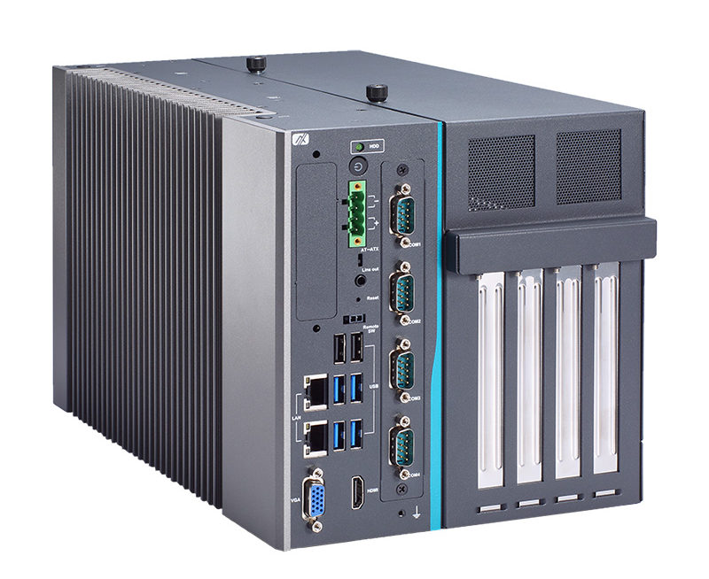
4-slot Industrial System with LGA1151 Socket Intel® Xeon® E3 v5, 7th/6th Gen Intel® Core™ i7/i5/i3 & Celeron® Processor, Intel® C236/Q170, Front-access I/O, PCIe/PCI Slots.

Axiomtek – a world-renowned leader relentlessly devoted in the research, development and manufacture of series of innovative and reliable industrial computer products of high efficiency – is pleased to announce the release of IPC974-519-FL, its newest 4-slot fanless industrial system. This robust IPC system provides edge computing capabilities for a wide variety of industrial AIoT applications, such as real-time control, data analysis, deep learning and automated optical inspection, making great strides to utilize an ideal solution. The industrial PC is powered by the high-performance Intel® Xeon® E3 v5, 7th/6th generation Intel® Core™ (codename: Kaby Lake/Skylake) or Celeron® processors with the Intel® C236 chipset or Q170 chipset. It also supports powerful NVIDIA® GPU with up to 300W TDP. In addition, the system has a wide operating temperature range of -10°C to +70°C with 0.5 m/s airflow and a wide range of 19V to 30V DC power input for harsh operating environments.

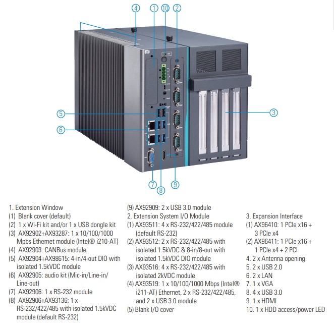
“The IPC974-519-FL has a flexible I/O window slot for ease of customization to meet the requirements of various applications. It has a choice of four different types of I/O modules – a four-port RS-232/422/485 module (AX93511); a four-port isolated RS-232/422/485 module (AX93516); a one-port GbE Ethernet, two-port USB 3.0 and two-port RS-232/422/485 module (AX93519); and a two-port isolated RS-232/422/485 and 8-in/8-out DIO module (AX93512). Additionally, it provides four high speed and full-size PCIe /PCI slots supporting the vision, motion, data acquisition and I/O cards. The AIoT industrial automation computer has an optional built-in power board which provides 300W power to add-in graphics card,” said Ivy Lee, a product manager of Product PM Division at Axiomtek. “To satisfy the wide temperature variations, it also offers an easy-to-install fan module to help dissipate heat generated within the system when high power consumption PCI/PCIe cards are installed.”

Axiomtek has combined this advanced 4-slot industrial system with Cognex VisionPro, the PC-based vision software from Cognex, to provide a first-class automated optical inspection solution. It also includes Intel® AMT 11.0 for easy remote management and Trusted Platform Module (TPM) 2.0 for optimum security. The highly versatile and reliable IPC974-519-FL is equipped with two easy-swappable 2.5″ HDDs with Intel® RAID 0,1,5 for extensive storage needs. It also comes with dual DDR4-2133 ECC/non-ECC SO-DIMM slots with up to 32GB system memory. The industrial computer features a wide choice of front-facing I/O connectors, including two LAN ports, four USB 3.0 ports, two USB 2.0 ports, one VGA, one HDMI, one 4-pin terminal block, and one audio (line-out). There is also a full-size PCI Express Mini Card slot with SIM slot (USB & PCIe interface) for 3G/4G, GPS, Wi-Fi, Bluetooth or other RF connections. Moreover, the IPC974-519-FL has two SMA type antenna holes.

Advanced Features:

  • LGA1151 socket Intel® Xeon® E3 v5, 7th/6th gen Intel® Core™ i7/i5/i3 & Celeron® processor, up to 80W (codename: Kaby Lake/Skylake)
  • Intel® C236/Q170 chipset
  • Supports 4 expansion slots for full-size add-in cards
  • Supports system power on delay function
  • -10°C to +70°C operating temperature range
  • Supports ECM BIOS setting
  • Supports Intel® RAID 0,1,5
  • Supports NVIDIA® GPU (up to 300W TDP)
  • Supports TPM 2.0
  • Supports Intel® AMT 11.0

Axiomtek’s IPC974-519-FL is now available for purchase. For more product information or customization services, please visit our global website at www.axiomtek.com or contact one of our sales representatives at info@axiomtek.com.tw.

MaaXBoard I.MX 8M Based SBC Runs Android 9.0 Or Yocto Linux

We have written about a host of i.MX8M based SBCs, like Seco’s SBC-C20, Boundary Devices’ Nitrogen8M, Arrow’s 96Boards CE Extended Thor96, SolidRun’s HummingBoard Pulse, and the armStone MX8M from F&S. However, we have come across another i.MX8M based SBC. Embest has launched a $60 “MaaxBoard” SBC which runs Yocto Linux or Android 9.0 on a quad -A53 i.MX8M, and features 2GB to 4GB DDR4, 4K playback, and a Raspberry Pi-like layout and 40-pin header.

Embest is a Chinese manufacturer that switched to Avnet when it acquired Premier Farnell. They have begun selling the Raspberry Pi-like SBC. Typical applications for the SBC include Human-Machine Interfaces (HMI), entertainment, AI device, building automation, education, machine vision, medical imaging, and embedded computing.

We realize that often times, most individually priced SBCs under $100 ship with open hardware specs and community support features, but it appears to be a different case with the MaaxBoard. However, Embest offers hardware and software documentation, and also an image and source code for a Yocto Project based distribution based on Linux 4.14.78. It also offers support for Android 9.0. It’s uncertain if the lone $60 package offers you the i.MX8M Dual, QuadLite, or Quad model. The 1.5GHz Cortex-A53 i.MX8M also includes a Cortex-M4F real-time core and a 4K-ready Vivante GC7000Lite/GC7000VLX GPU. Embest clocks the SoC at 1.4GHz.

The $60 price seems to include 2GB RAM and an empty eMMC socket. The product page mentions “up to” 2GB DDR4 SDRAM and “0 ~ 64GB” eMMC, but Embest’s SlideShare preview presentation from June lists a default of 2GB RAM but no specific eMMC listing. The MaaxBoard is also equipped with a MicroSD slot, an 802.11ac/Bluetooth 4.x module, and a GbE port. Available also is 2x USB 3.0 ports, a power-only USB Type-C port, MIPI-DSI and CSI connectors, and some high-end SPDIF and SAI digital audio interfaces.

Maaxboard mini

By the end of the year, MaaxBoard will be joined by a very similar MaaXBoard Mini SBC equipped with NXP’s i.MX8M Mini SoC, that should be even more efficient thanks to the 14nm processor, but the price has not been announced yet. Embest has already posted a teaser page with some photos but no details. The image indicates that the HDMI port has been removed and replaced with one of the dual USB 3.0 ports. The i.MX8M Mini offers up to four faster, 1.8GHz Cortex-A53 cores with lower power consumption but is limited to HD video.

The board ships in an anti-static bag with a generic safety leaflet. That means you need to source your own USB-C power supply and cables.

The MaaXBoard is available now for $60, presumably with 2GB DDR4 and WiFi/BT, and comes with an empty eMMC socket. The unpriced MaaXBoard Mini will ship later this year. More information can be found in the Embest (Avnet Manufacturing Services) MaaXBoard announcement, MaaXBoard shopping page, and Dropbox wiki, as well as the MaaXBoard Mini teaser page.

Specifications listed for the MaaxBoard include:

  • Processor — NXP i.MX8M Dual, QuadLite, or Quad (2x or 4x Cortex-A53 @ up to 1.4GHz); Vivante GC7000Lite GPU; VPU on all but QuadLite; Cortex-M4F @ 266MHz
  • Memory/storage – 2GB to 4GB DDR4
  • eMMC socket for up to 64GB
  • MicroSD slot
  • Networking/wireless:- 10/100/1000 Ethernet port, 802.11ac with Bluetooth 4.x with ant. connector.
  • Media I/O: HDMI 2.0a port with audio for up to 4k@60, MIPI-DSI, MIPI-CSI, SPDIF/UART and SAI audio connectors plus SAI/I2S on 40-pin, Supports more than 20 audio channels each @384KHz with DSD512.
  • Other I/O: 2x USB 3.0 host ports, USB Type-C port with 5V power input only, 7x and 8x GPIO connector.
  • Expansion — 40-pin GPIO connector (“partially” RPi HAT compatible) with I2C, SPI, UART, I2S, etc.
  • Other features — Power and user buttons; 2x LEDs
  • Power — 5V/3A via USB Type-C
  • Operating temperature — 0 to 70°C with 20% ~ 90% humidity resistance
  • Dimensions — 85 x 56 x 12mm
  • Operating system — Yocto image with Linux 4.14.78 and source code; Android 9.0 support

The MaaXBoard is available for $60, presumably with 2GB DDR4 and WiFi/BT, but with an empty eMMC socket. The unpriced MaaXBoard Mini will ship later this year. More information may be found in the Embest (Avnet Manufacturing Services) MaaXBoard announcement, MaaXBoard shopping page and Dropbox wiki, as well as the MaaXBoard Mini teaser page.

Glasgow Interface Explorer for exploring digital interfaces

A highly capable and extremely flexible open source multitool for digital electronics. Explore digital interfaces on ease.

What is Glasgow Interface Explorer?

Glasgow is a tool for exploring digital interfaces. It is designed for embedded developers, reverse engineers, digital archivists, electronics hobbyists, and anyone else who wants to communicate with a wide selection of digital devices while enjoying maximum reliability and minimum hassle. It can be attached to most devices without additional active or passive components, and it provides extensive protection from unexpected conditions and operator error.

The Glasgow hardware can support many digital interfaces because it uses reconfigurable logic. Instead of offering just a small selection of standard hardware supported interfaces, it uses an FPGA to adapt on the fly to the task at hand without compromising performance or reliability, even for unusual, custom or obsolete interfaces.

The Glasgow software is a set of building blocks designed to eliminate incidental complexity. Each interface is packaged into a self-contained applet that can be used directly from the command line or integrated into a more complex system. Using Glasgow does not require any programming knowledge, though it is much more powerful if you know a bit of Python.

Features

Below are a few of the tasks that Glasgow already performs quite well:

  • Communicating via UART
    • Automatically determining and following the baud rate of the device under test
  • Initiating transactions via SPI or I²C
  • Reading and writing 24-series EEPROMs
  • Reading and writing 25-series Flash memories
    • Determining memory parameters via SFDP
  • Reading and writing ONFI-compatible Flash memories
  • Determining memory parameters via ONFI parameter page
  • Programming and verifying AVR microcontrollers with SPI interface
  • Automatically determining unknown JTAG pinouts
  • Playing back JTAG SVF files
  • Debugging ARC processors via JTAG
  • Debugging some MIPS processors via EJTAG
  • Programming and verifying XC9500XL CPLDs via JTAG
  • Synthesizing sound using a Yamaha OPL chip and playing it in real time on a webpage
  • Reading raw modulated data from 5.25” and 3.5” floppy drives
  • …and much more!

Everything above can be done with only a Glasgow revC board, some wires, and – depending on the device under test – external power. No additional frontend circuitry is needed.

Technical Specifications

  • iCE40HX8K Lattice Semiconductor FPGA (supported by a fully open source FPGA flow)
  • FX2 HighSpeed USB interface capable of saturating 480 Mbps throughput
  • Two 8-channel GPIO banks provide 16 highly flexible GPIO
  • Each GPIO is capable of a theoretical speed up to 100 MHz (actual speed depends on many factors)
  • Each GPIO has a dedicated level shifter with individual direction control
  • Each GPIO has a dedicated, software controlled 10 K Ohm Pull-Up/-Down resistor
  • Each GPIO bank has a dedicated programmable linear voltage regulator, configurable from 1.8 V to 5 V and capable of providing up to 150 mA of power
  • Each GPIO bank has a dedicated sense ADC capable of monitoring the GPIO bank voltage
  • All GPIO have ESD protection diodes
  • An optional set of 14 differential pair GPIO, connected directly to the FPGA without any frontend circuitry, can be used for high speed interfaces
  • A dedicated SYNC connector
  • Five user-controllable LEDs connected to the FPGA
  • Five status LEDs

Legend

How Can I Learn More?

Visit the Glasgow GitHub project page, and ask away in the glasgow Freenode IRC channel or on the 1BitSquared Discord server, and follow esden and whitequark on Twitter.

Pixblasters Video LED Controller transform LED strips to huge displays

Combine LED strips to create a huge display that acts as a regular video monitor. All this with the FPGA based RGB LED controller that is capable of controlling up to 16,384 WS2812 based RGB LEDs at 60 FPS. Not only that, but you can daisy chain multiple controllers which can control up to hundreds of thousands of LEDs.

Due to their high cost and complexity, huge, shiny, beautiful video displays with thousands of LEDs have always been out of reach of enthusiasts and small business owners. Pixblasters MS1 changes all of that.

Pixblasters demo. Display made using LED strips glued to aluminum plates.

Pixblasters MS1 enables DIY enthusiasts and signage professionals, even those with minimal technical skills, to turn a bunch of addressable RGB LED strips into immense video LED displays. This FPGA-based LED controller enables new levels of professional-grade digital signage that cannot be attained by standard LED modules. The LED strips can be curved and glued to different surfaces to form giant yet economically viable video installations that can span entire buildings.

Key Features

  • Easy to use with any computer, any OS:
    Pixblasters connects to any computer as an ordinary external monitor, with no programming needed. You can use it with Raspberry Pi, PC, media boxes, phones, etc. Simply plug in the monitor cable and the controller will smoothly drive the LEDs at the maximum frame-rate of 60 fps.
  • Straightforward display content and management:
    Anything that shows in the selected part of monitor image shows on the LEDs as well. No need for special software for anti-aliasing or fonts. Use any digital signage software and add layered screen divisions, text, animations, video, RSS… LEDs work at their maximum speed and are perfectly synchronized, no matter the number of LEDs and chained MS1 controllers, or the display size.
  • Display size and resolution:
    A single MS1 can control 4.7/17.7 m² (~ 50.6/190.5 ft²) while daisy-chained MS1s can control an LED display of hundreds of square meters using thirty to sixty LED strips. Daisy-chained controllers that drive a total of 16,384 LEDs can support HD LED displays.
  • Remote controllable and customizable:
    Control it remotely from anywhere in the world through the network interfaces of the driving computer. Don’t worry about the LED display’s architecture. Users with special display applications (such as big, real-time timetables and scoreboards) can develop custom software for a computer monitor.
  • Open source FPGA demo:
    Use the hardware platform for experimenting with, and learning about, driving RGB LEDs. Note: the open source FPGA demo design supports a subset of the fully-featured Pixblasters MS1 LED controller.

Features

  • Xilinx® Spartan®-6 XC6LX9-3 FPGA chip
  • On-board Microchip PIC18F26J50 microcontroller:
    • The microcontroller connects to the PC, runs the configuration software, and permanently stores the configuration data. It also enables simple firmware updates with any new features.
  • Output resolutions (H x V): 512 x 32 (native), 256 x 64, 128 x 128, 180 x 96, etc.
  • Board dimensions: 95 x 100 mm
  • LED details:
    • 32 LED digital outputs: up to max. 512 LEDs per output
    • Maximum WS2812B/SK6812 LED display frame rate: 60 fps
    • Currently supported LED types: WS2811, WS2812, WS2812B, SK6812
    • Supports RGB666 (256K colors) color format
    • Maximum driving capacity of the single MS1 controller is 16,384 RGB LEDs
    • 5 VDC 24 mA digital outputs compatible with the most popular RGB LED types
  • Connectivity:
    • HDMI video input allows for easy connection from the computer – it also works with adapter cables should your computer have a DVI® output
    • Push-in strip power and signal connectors enable easy wiring without soldering
    • Validated with different computers and different OS’s: Raspberry Pi Linux, Microsoft® Windows® PC, media boxes, phones and tablets…
    • On-board EDID flash enables automatic connection to any computer and any OS
  • Power:
    • Protected 5 VDC power supply input
    • The LED power supplies need to be wired separately to fulfill the power and current requirements of giant LED displays
  • Display controls:
    • Cropping image window
    • Display formatting
    • LED timing parameters
    • Supports different video resolutions (max. 720p – 1280 x 720 at 60 fps)
    • Integrated video input cropping and mirroring
    • Multiple lines per output mode
    • LED gamma correction
  • Daisy-chain multiple controllers:
    • Each MS1 board can work either as the Master or the Slave video controller
    • Daisy-chained controllers can drive more than 200,000 perfectly synchronized LEDs differently arranged in HD LED displays
    • The high-speed video link between MS1 boards assures max. fps and synchronicity
    • Low-speed control link interface
    • Video and control links use common UTP cables (Ethernet)
    • On-board DIP switches allow for an easy selection of the Master, Slave and six other FPGA configurations, including user-defined FPGA configurations
    • A single digital output has the ability drive multiple output video horizontal lines
    • Configuration is fully customizable through a menu on the PC connected via the USB serial cable

The project is live on Crowd Supply and basic pledge for Pixblasters Go costs $219.

NLM0011/NLM0010- LED Driver IC with effective NFC-PWM programming

Infineon Technologies developed the NFC-PWM series (NLM0011 & NLM0010) for fast and cost effective implementation of NFC programming for LED drivers. The NFC programming can replace the labor intensive “plug-in resistor” current setting method with the contact less NFC interface. It improves the operational efficiency and flexibility in value chain by implementing automatic programming in the manufacturing line. With this it reduces the LED driver variants, simplifies the selection of LED modules, and allows end-of-line configuration.

The devices are NFC wireless configuration ICs with configurable PWM output primarily designed for LED applications. It enables cost effective NFC programming implementation by using a PWM signal directly to control the analog driver IC which eventually reduces the cost of BOM.

These devices can operate in two different modes,  Active and Passive Mode. When the device is in passive mode the LED driver is not powered and the configurations of PWM parameters can be done via the NFC interface. When the device is in Active mode, it is powered by a Vcc Voltage supply, and a PWM output is generated according to the stored parameters. The PWM signal is converted into a desired DC voltage to control the current output of an LED driver by using an external R/C filter.

Features

  • Configurable pulse width modulation (PWM) output
  • NFC contactless interface compliant to ISO/IEC 18000-3 mode 1 (ISO/IEC 15963)
  • Constant light output (CLO) with 8 configurable points
  • Integrated operation-time counter (OTC) and on/off counter
  • Non-volatile memory (NVM) including UID and 20 bytes free memory for user data
  • Stable PWM output with fixed 2.8 V amplitude and +/-0.1% duty cycle accuracy

NLM0011 has the Integrated constant lumen output (CLO) function which compensated the luminous flux drop (aging effect) of the LED module by automatically adjusting the LED current to the aging characteristics of the LEDs. NLM0011 automatically adjusts the PWM duty cycle to compensate the LED degradation with the help of integrated operation time counter (OTC) and stored LED degradation curve in the CLO table.

There is no need for firmware development efforts as the device can fit perfectly to the mainstream analog driver ICs and can easily adapt into the existing designs to replace the “Plug-in- resistor” current configuration concept. The solution can easily go along with the existing analog LED driver designs and the NFC programming specification form the module –Driver interface special interest Group (MD-SIG). The NFC-PWM series can also be used in applications such as motor control and SMPS. The NLM0011 and NLM0010 can be ordered now in a SOT23-5 package, for more information you can use the datasheet or product page from Infineon.

Free Elektor Article: TMC2160 Motor Driver Board

Stepper motors are popular in computer and microcontroller-based position control applications like robotics, industrial automation, CNC machines, 3D printers and video camera control. Due to their uncomplicated internal construction and their limited number of connection wires, stepper motors look deceptively simple. On the internet, there are even lots of tutorials on how to control these motors using an antique L293D driver IC and an Arduino, but for serious applications everything depends on the quality and the capabilities of the motor driver.

… read more

OneMix 3Pro Mini Laptop is Powered by Intel Core i5-10210Y Comet Lake-Y Processor

After the release of several models of the One Mix mini laptops from One Netbook, like the One Mix 2S Yoga and the One Mix 3 Yoga, the company has recent just unveiled its intentions to launch another new model of the One Mix mini laptop called; One Mix 3 Pro, which is expected to come with an upgraded processing capacity for an improved performance for multi-threaded applications.

The upcoming One Mix 3 Pro is the first computer of its size to come with the 10th generation Intel Core “Comet Lake” processor. Instead of the 8th gen Core “Amber Lake” processors on previous models, the One Mix 3 Pro mini laptop is equipped with the Intel 10th generation Y-series Comet Lake processor – Comet Lake-Y Intel Core i5-10210Y processor with a 7W TDP – and designed for low power high performance output.

The mini laptop has dimensions 204 x 129 x 14.9mm, weighs around 660 grams and is allegedly said to be a convertible 2 in 1 tablet as it comes with a 360 degree hinge. It also comes with a 8.4 inch 2560 x 1600 pixel touch screen display, a backlit keyboard, and a fingerprint scanner for user input at the top right of the laptop. For system memory, the One Mix 3 pro comes with a dual channel 16GB LPDDR3 RAM, a microSD card reader and a 512GB NVMe SSD for storage.

Other features of the One Mix 3 Pro mini laptop include:

  • One micro HDMI port for video output
  • One USB “full function” type-C port and another USB 3.0 port for USB connection.
  • GPU – 24 EU Intel HD 615 graphics, up to 1.05GHz (300MHz – 1.05 GHz)
  • 3.5mm audio jack and digital audio via HDMI
  • Mouse buttons, headset
  • Support for a 4096 degree of pressure-sensitive optional pen.
  • Intel Core i5-10120Y Amber Lake-Y processor
  • System Memory – dual channel 16GB LPDDR3 RAM
  • Base/Turbo speed – 1.0 GHz / 4.0 GHz and 6MB cache
  • Cores/Threads – 4/8
  • Battery – 8,600mAh battery that supports 5V / 9V / 12V charger.

The One Mix mini laptop is expected to ship with a Windows 10 Home Edition operating system and should work with other version of windows. There is no word yet from One Netbook about pricing and availability of this mini laptop, but as one can guess, it should cost more than the previous One Mix models.

One Netbook plans to start selling the mini laptop in November, and they are likely to make it available through international resellers immediately after.

USB Armory Mk II USB Linux Computer Targets Security Applications

F-Secure Foundry recently launched a crowdfunding campaign for their new, tiny form factor USB Armory MK II computer. The device which comes with a form factor that looks like a usb flash drive is an open-source, full featured USB computer with Bluetooth, USB-C ports, 512MB RAM and 900MHz and was developed as an improvement to the USB Armory computer dongle launched far back in 2014.

The USB Armory MK II comes with the more efficient NXP i.MX6ULZ ARM Cortex TM – A7 processor, a 16GB eMMCflash memory chip and new security features like;

  1. High Assurance Boot (HABv4) that enables the on-chip internal Boot ROM to authenticate the initial boot loader with a digital signature.
  2. Secure non-volatile storage that includes a secure RTC, master key control, security state machine and tamper/violation detection and reporting.
  3. True Random Number Generator which when included in the Linux kernels enables the component within the Linux framework.
  4. External cryptographic co-processors (A71CH and ATECC) that provide high-endurance monotonic counters used for external verification of firmware rollback/downgrade attacks.
  5. eMMC Replay Protected Memory Blocks that feature replay – protected authenticated access to flash memory using a shared connection between the eMMC and the host.

All of these features are not surprising, as, according to F-secure foundry, the USB MK11 was developed to help users with potential security applications like;

  1. Password manager with integrated web server
  2. OpenSSH client and agent for untrusted hosts
  3. Router for end-to-end VPN tunneling
  4. Portable penetration testing platform
  5. Hardware security module
  6. Tor bridge
  7. Authentication token

Some of the highlight features of the USB Armoury MK11 hardware include;

  1. NXP i.MX6ULZ ARM Cortex TM – A7 Processor at 900MHz
  2. U-blox ANNA-B112 BLE Bluetooth module
  3. 512MB DDR3 RAM
  4. USB 2.0 port and 2 USB type-C ports (Dual Role Power Receptacle and Upstream Facing Port
  5. Small form factor (Dimension – 66mm x 19mm x 8mm )
  6. Slide switch for boot mode selection between microSD and eMMC
  7. External security elements – NXPA71CH + Microchip ATECC608A

Intro Video

The NXP i.MX6ULZ ARM Cortex TM – A7 processor along with superior speed (900MHz) and other features that meet current trend like USB-C ports are some of elements that gives the new MK11 an edge over the earlier MK1. A summary of the features of both boards is provided in the table below to highlight the difference between them.

The USB Armory MK II supports full TCP/IP connection to/from it via USB CDC Ethernet emulation along with wireless connectivity over BLE, and serial communication over USB or physical UART using the Debug board. It should be noted that HDMI video is not supported over the 2 USB-C ports; only the USB 2.0 protocol is supported over the USB-C ports.

More details on the USB Armory MK II and the Crowdfunding campaign can be found on the project page on Crowdsupply. Over $20000 has already been committed by backers and all orders are expected to be shipped by the end of 2019 or in early 2020 with free shipping to backers in the US and a $15 service charge to ship to the rest of the world.

3µm microLEDs transferred by the millions

Taiwanese startup Mikro Mesa Technology has announced a major breakthrough in the mass transfer of microLEDs, with a non-compression low temperature bonding process allowing millions of microLEDs to be transferred in one step. by Julien Happich @ www.eenewsled.com

Blue-green two-color pixel structure at a pitch of under 5µm. (Photo/Mikro Mesa)

The company started cooperation with Chinese custom LCD display manufacturer Nanjing CLP Panda in 2017 and it took two years of development to deliver the first 3µm microLED chips. The ultra-small pixels means more microLEDs come out of the epitaxial wafers, and the mass transfer from wafers as large as 4-inch in diametre means up to millions of pixels can be transferred at a time, including multi-color microLEDs arrays. The large transfer area also reduces the number of necessary transfers for the production of large-size full-color displays, increasing yield.
According to Mikro Mesa insiders, the display technology can produce high-precision displays up to 1,800 dpi and could be applied to 55-inch or higher microLED TVs. The company anticipates the mass transfer process will make its microLEDs competitive with OLEDs for screens in wearables, smart phones, and AR headsets.

5µm die display samples made with Mikro Mesa’s massive transfer technology. (Photo/Mikro Mesa).

What’s more, due to its low process temperature, the technology is compatible with flexible and transparent substrates, enabling the design of transparent displays with much higher performance than today’s AMOLED displays.

Tiny Reflow Controller with character LCD

Reflow ovens are an important part of the development of PCB for electronic products when using surface mount components. They provide a route through which PCBs can be quickly populated with SMD components, however, for accurate results, the heat across the oven needs to be controlled and timed correctly. To achieve this, manufacturers use a kind of controller, like “Tiny Reflow Controller”, and with several DIY reflow ovens being used by makers around the world, we thought it would be a good fit for today’s tutorial to focus on the development of DIY Reflow Oven Controller.

As mentioned above, reflow oven controllers are quite important in ensuring just the right amount of heat is applied in the soldering process for SMD components and this importance has led to the development of quite a number of different Reflow oven controller projects, which someone can find on the internet. However, for today’s tutorial, we will look at the first version of Rocket Stream’s tiny Reflow Oven Controller v1 which is probably the most well tested DIY reflow oven controller on the internet, as it is the one being used by Rocket Stream themselves for the manufacturing of their boards.

Tiny Reflow Controller with character LCD – [Link]

TOP PCB Companies