Reflow ovens are an important part of the development of PCB for electronic products when using surface mount components. They provide a route through which PCBs can be quickly populated with SMD components, however, for accurate results, the heat across the oven needs to be controlled and timed correctly. To achieve this, manufacturers use a kind of controller, like “Tiny Reflow Controller”, and with several DIY reflow ovens being used by makers around the world, we thought it would be a good fit for today’s tutorial to focus on the development of DIY Reflow Oven Controller.
As mentioned above, reflow oven controllers are quite important in ensuring just the right amount of heat is applied in the soldering process for SMD components and this importance has led to the development of quite a number of different Reflow oven controller projects, which someone can find on the internet. However, for today’s tutorial, we will look at the first version of Rocket Stream’s tiny Reflow Oven Controller v1 which is probably the most well tested DIY reflow oven controller on the internet, as it is the one being used by Rocket Stream themselves for the manufacturing of their boards.
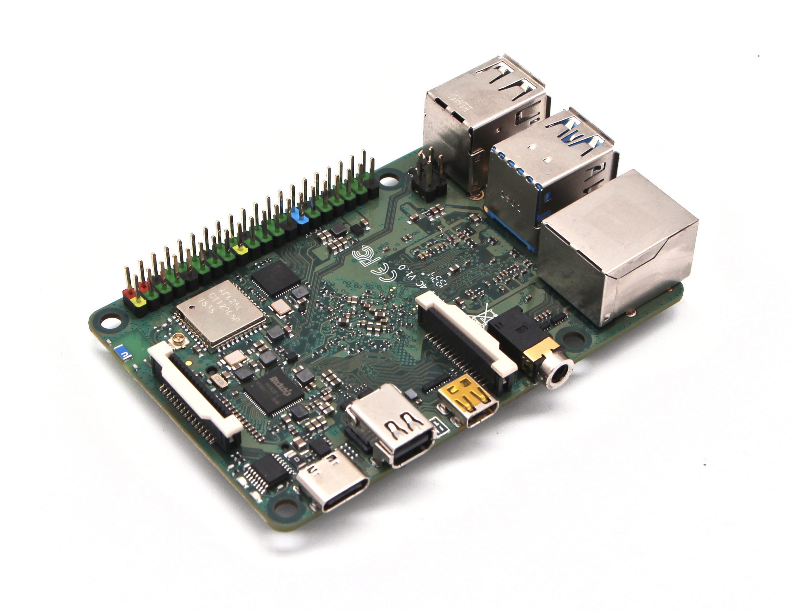
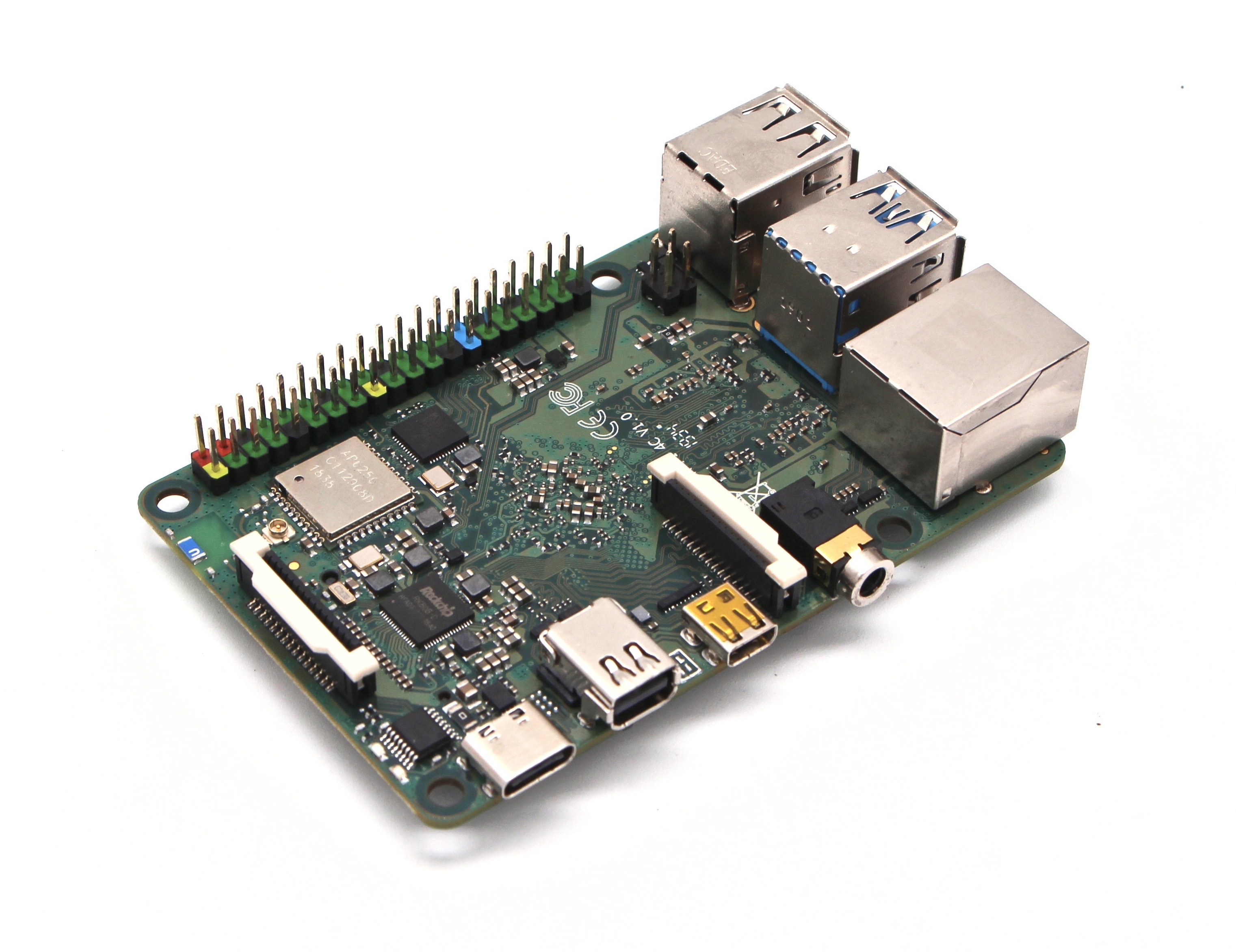
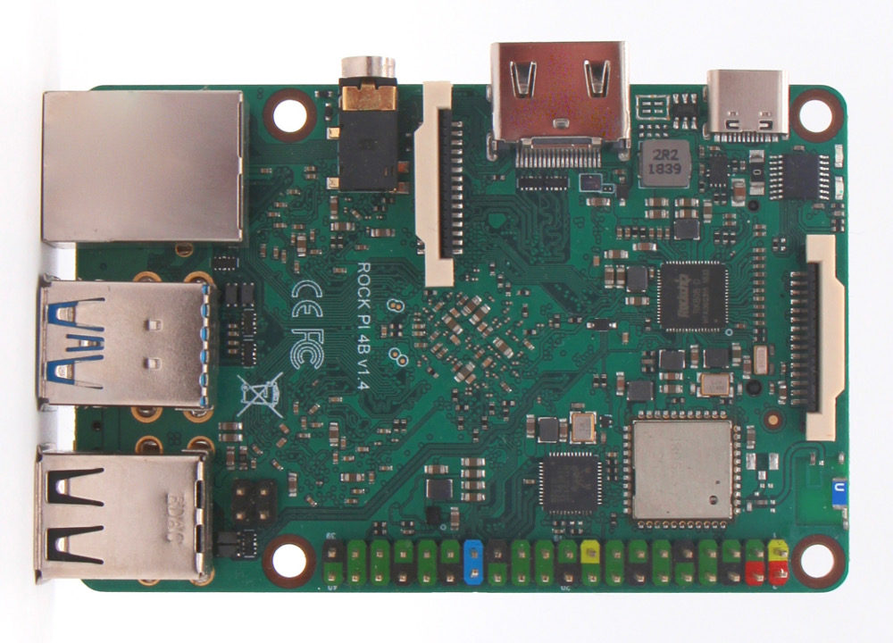
The Rocket Stream’s Reflow Oven Controller v1 is powered by the ATtiny1634R and uses the latest thermocouple sensor interface IC MAX31856 from Maxim. It is one of the cheapest designs on the internet as Rocket Stream was able to reduce the overall cost of the design by not using a development board like the Arduino and using as many SMD parts as possible in place of through-hole components, to reduce the time that goes in and the work involved leaving only the terminal block and the LCD connector as the only through-hole components.
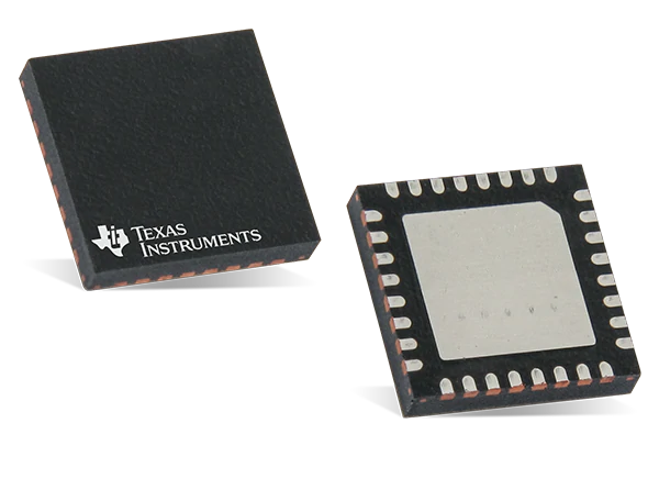
The ATtiny1634R is one of the new ATtinys we discussed in the last article. It is a High Performance, Low Power AVR® 8-bit Microcontroller with Advanced RISC Architecture, 16K Bytes of In-System, Self-Programmable Flash Program Memory and 256 Bytes of In-System Programmable EEPROM with support for up to 100,000 Write/Erase Cycles. It comes In-System Programmable via SPI Port and can be programmed using the Arduino IDE.
Other components involved include an external Solid State Relay (SSR) which should be rated according to the current draw of your oven (heater) and a K type thermocouple which provides temperature feedback to the controller and an LCD on which information/status of the system is displayed.
At the end of this project, you know the workings behind the Tiny Reflow Controller and you will have built up the courage required to attempt building one by yourself.
Required Components
The following main components are required to build the project:
- ATtiny1634R
- MAX31856 thermocouple interface
- K-Type Thermocouple(Rocket stream recommends those with fiberglass or steel jacket
- 8×2 LCD black character with yellow backlight
- 2 push button
- 1 red LED
- 2 Terminal Blocks
- 1 Transistor
- 1 Buzzer
Yes you guessed right. The list is definitely longer than this but so things doesn’t get messy, other components that are required are provided in the table below
Component Count: 51
| Ref | Qnty | Value | ||||
|---|---|---|---|---|---|---|
| C1, C2 | 2 | 10nF | ||||
| C3, C6, C7, C8, C9 | 5 | 100nF | ||||
| C4, C5 | 2 | 1uF 16V X7R | ||||
| C10, C11, C12 | 3 | 10uF 10V X5R | ||||
| D1 | 1 | Red | ||||
| D2 | 1 | PMEG3020CPA | ||||
| D3 | 1 | 1N4148WS | ||||
| J1, J2 | 2 | TERMINAL-BLOCK-1×2 | ||||
| J3 | 1 | MICRO-USB | ||||
| J4 | 1 | 2.54mm 2×3 | ||||
| J5 | 1 | 2.54mm 1×6 | ||||
| L1 | 1 | BLM18KG221SN1D | ||||
| LOGO1 | 1 | LOGO-ROCKET-SCREAM | ||||
| LOGO2 | 1 | LOGO-KICAD | ||||
| LOGO3 | 1 | LOGO-ROCKET-SCREAM | ||||
| LOGO4 | 1 | LOGO-OSHW | ||||
| LS1 | 1 | HYG9605B | ||||
| M5, M6 | 2 | FIDUCIAL | ||||
| Q1, Q2 | 2 | 2N3904 | ||||
| R1 | 1 | 35WR10KLFTR | ||||
| R2, R3 | 2 | 100R | ||||
| R4, R5, R9, R10 | 4 | 10K | ||||
| R6 | 1 | 2K2 | ||||
| R7 | 1 | 27K | ||||
| R8 | 1 | 53K6 | ||||
| SW1, SW2 | 2 | IT-1109S | ||||
| SW3 | 1 | TS-018 | ||||
| U1 | 1 | ATTINY1634R-MU | ||||
| U2 | 1 | MCP1700T-3302E/MB | ||||
| U3 | 1 | MAX31856 | ||||
| U4 | 1 | RT0802A |
This BOM is also attached in the zip file under the download section and could be used to place the order for all the components at once.
Schematics
Since most of the components to be used are SMD, it only makes sense to implement this project on a PCB. However, users can choose to get the through-hole version of the components so it can be implemented on a breadboard. The schematics for the project is shown in the image below.
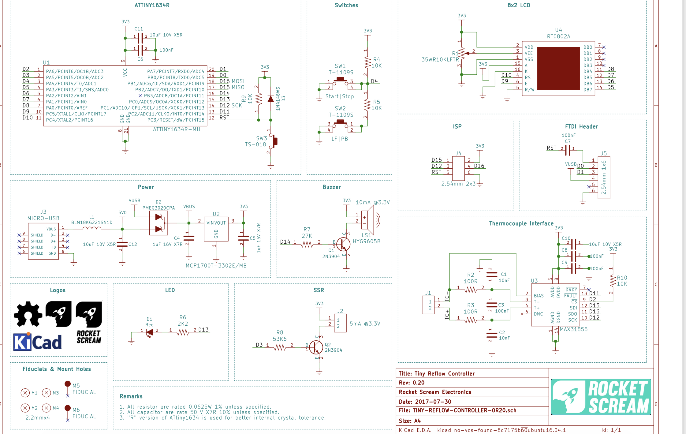
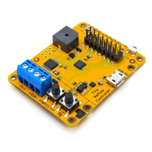
The schematics and the resulting PCB were developed with KICAD and the files are attached in the zip file under the download section. You can edit the design to make whatever modification you want or just use the Gerber files which have already been generated to produce your own PCB. An image of the tiny reflow oven controller is shown below.
Code
We will use the Arduino IDE to develop the code for today’s project, as such, you will need to install the Arduino IDE board support files for the ATTINY1634R microcontroller so it can be programmed using the Arduino IDE. Check out our tutorial on setting up the Arduino IDE to program ATtiny based microcontrollers to get some help.
The sketch for today’s project is based on the example code shipped by Rocket Stream. It runs the reflow process via a PID control algorithm that is based on the awesome Arduino PID library written by Brett Beauregard. The sketch simply evaluates the current heat level, compares it with what the value should be at that particular reflow stage and adjust itself using the PID algorithms to ensure it’s up to par.
Asides the PID Library, other libraries used for the project include; the Liquid Crystal Library which was used to interface with the LCD, the Adafruit Max31856 library which was used to interface with the thermocouple, and the Arduino EEPROM library which was used to manage the storage and extraction of data on the EEPROM. While the EEPROM library comes with the Arduino IDE, the other libraries can be installed via the Arduino library manager.
As usual, I will do a brief explanation of the code highlighting the major parts. The example code we will work with, takes into account both leaded and lead-free reflow oven configurations, allowing users to change from one to the other via a push button.
We start the sketch by including all the libraries that we will use, after which we create a type definition that holds several parameters to indicate the state of the reflow process.
// ***** INCLUDES *****
#include <EEPROM.h>
#include <LiquidCrystal.h>
#include <Adafruit_MAX31856.h>
#include <PID_v1.h>

// ***** TYPE DEFINITIONS *****
typedef enum REFLOW_STATE
{
  REFLOW_STATE_IDLE,
  REFLOW_STATE_PREHEAT,
  REFLOW_STATE_SOAK,
  REFLOW_STATE_REFLOW,
  REFLOW_STATE_COOL,
  REFLOW_STATE_COMPLETE,
  REFLOW_STATE_TOO_HOT,
  REFLOW_STATE_ERROR
} reflowState_t;
We also create other type declarations to hold the reflow status, switch status, debounce state and the Reflow_Profile based on the switch status.
typedef enum REFLOW_STATUS
{
  REFLOW_STATUS_OFF,
  REFLOW_STATUS_ON
} reflowStatus_t;

typedef	enum SWITCH
{
  SWITCH_NONE,
  SWITCH_1,
  SWITCH_2
}	switch_t;

typedef enum DEBOUNCE_STATE
{
  DEBOUNCE_STATE_IDLE,
  DEBOUNCE_STATE_CHECK,
  DEBOUNCE_STATE_RELEASE
} debounceState_t;

typedef enum REFLOW_PROFILE
{
  REFLOW_PROFILE_LEADFREE,
  REFLOW_PROFILE_LEADED
} reflowProfile_t;
Next, we create variables to hold constant values that will be used irrespective of the profile selected (General Profile constant) and we follow it up by creating variables to hold values specific to Lead-free profile and also create those specific to the leaded profile. This ensures that irrespective of the profile selected by the user, the necessary information will be available.
// ***** CONSTANTS *****
// ***** GENERAL PROFILE CONSTANTS *****
#define PROFILE_TYPE_ADDRESS 0
#define TEMPERATURE_ROOM 50
#define TEMPERATURE_SOAK_MIN 150
#define TEMPERATURE_COOL_MIN 100
#define SENSOR_SAMPLING_TIME 1000
#define SOAK_TEMPERATURE_STEP 5

// ***** LEAD FREE PROFILE CONSTANTS *****
#define TEMPERATURE_SOAK_MAX_LF 200
#define TEMPERATURE_REFLOW_MAX_LF 250
#define SOAK_MICRO_PERIOD_LF 9000

// ***** LEADED PROFILE CONSTANTS *****
#define TEMPERATURE_SOAK_MAX_PB 180
#define TEMPERATURE_REFLOW_MAX_PB 224
#define SOAK_MICRO_PERIOD_PB 10000
Next, we create variables to be used by the PID Algorithm, followed by LCD messages and a few other variables. The names are very descriptive so it should be easy to follow.
// ***** PID PARAMETERS *****
// ***** PRE-HEAT STAGE *****
#define PID_KP_PREHEAT 100
#define PID_KI_PREHEAT 0.025
#define PID_KD_PREHEAT 20
// ***** SOAKING STAGE *****
#define PID_KP_SOAK 300
#define PID_KI_SOAK 0.05
#define PID_KD_SOAK 250
// ***** REFLOW STAGE *****
#define PID_KP_REFLOW 300
#define PID_KI_REFLOW 0.05
#define PID_KD_REFLOW 350
#define PID_SAMPLE_TIME 1000

// ***** LCD MESSAGES *****
const char* lcdMessagesReflowStatus[] = {
  "Ready",
  "Pre",
  "Soak",
  "Reflow",
  "Cool",
  "Done!",
  "Hot!",
  "Error"
};

// ***** DEGREE SYMBOL FOR LCD *****
unsigned char degree[8]  = {
  140, 146, 146, 140, 128, 128, 128, 128
};

// ***** PIN ASSIGNMENT *****
int ssrPin = 3;
int thermocoupleCSPin = 2;
int lcdRsPin = 10;
int lcdEPin = 9;
int lcdD4Pin = 8;
int lcdD5Pin = 7;
int lcdD6Pin = 6;
int lcdD7Pin = 5;
int buzzerPin = 14;
int switchPin = A1;

// ***** PID CONTROL VARIABLES *****
double setpoint;
double input;
double output;
double kp = PID_KP_PREHEAT;
double ki = PID_KI_PREHEAT;
double kd = PID_KD_PREHEAT;
int windowSize;
unsigned long windowStartTime;
unsigned long nextCheck;
unsigned long nextRead;
unsigned long updateLcd;
unsigned long timerSoak;
unsigned long buzzerPeriod;
unsigned char soakTemperatureMax;
unsigned char reflowTemperatureMax;
unsigned long soakMicroPeriod;
// Reflow oven controller state machine state variable
reflowState_t reflowState;
// Reflow oven controller status
reflowStatus_t reflowStatus;
// Reflow profile type
reflowProfile_t reflowProfile;
// Switch debounce state machine state variable
debounceState_t debounceState;
// Switch debounce timer
long lastDebounceTime;
// Switch press status
switch_t switchStatus;
switch_t switchValue;
switch_t switchMask;
// Seconds timer
int timerSeconds;
// Thermocouple fault status
unsigned char fault;
With all the variables created, we then create an instance of the PID, the LiquidCrystal, and the MAX31856 libraries after which we move to the void setup() function.
// PID control interface
PID reflowOvenPID(&input, &output, &setpoint, kp, ki, kd, DIRECT);
// LCD interface
LiquidCrystal lcd(lcdRsPin, lcdEPin, lcdD4Pin, lcdD5Pin, lcdD6Pin, lcdD7Pin);
// MAX31856 thermocouple interface
Adafruit_MAX31856 thermocouple = Adafruit_MAX31856(thermocoupleCSPin);
We start the void setup() function by checking the currently selected reflow profile on the EEPROM this helps determine which of the variable groups should be selected. If no reflow profile was previously stored, the system selects the Leadfree profile as default.
void setup()
{
  // Check current selected reflow profile
  unsigned char value = EEPROM.read(PROFILE_TYPE_ADDRESS);
  if ((value == 0) || (value == 1))
  {
    // Valid reflow profile value
    reflowProfile = value;
  }
  else
  {
    // Default to lead-free profile
    EEPROM.write(PROFILE_TYPE_ADDRESS, 0);
    reflowProfile = REFLOW_PROFILE_LEADFREE;
  }
Next, we initialize the SSR pin to ensure the reflow oven is open after which we initialize the buzzer setting it to turn on immediately the system powers up.
// SSR pin initialization to ensure reflow oven is off
  digitalWrite(ssrPin, LOW);
  pinMode(ssrPin, OUTPUT);

  // Buzzer pin initialization to ensure annoying buzzer is off
  digitalWrite(buzzerPin, LOW);
  pinMode(buzzerPin, OUTPUT);

  // LED pins initialization and turn on upon start-up (active high)
  pinMode(LED_BUILTIN, OUTPUT);
  digitalWrite(LED_BUILTIN, HIGH);
We also initialize the thermocouple, indicating the type, and also initialize the LCD and display a sort of splash screen with the date and version of the controller.
// Initialize thermocouple interface
  thermocouple.begin();
  thermocouple.setThermocoupleType(MAX31856_TCTYPE_K);

  // Start-up splash
  digitalWrite(buzzerPin, HIGH);
  lcd.begin(8, 2);
  lcd.createChar(0, degree);
  lcd.clear();
  lcd.print(" Tiny  ");
  lcd.setCursor(0, 1);
  lcd.print(" Reflow ");
  digitalWrite(buzzerPin, LOW);
  delay(2000);
  lcd.clear();
  lcd.print(" v1.00  ");
  lcd.setCursor(0, 1);
  lcd.print("26-07-17");
  delay(2000);
  lcd.clear();
Next, we initialize serial communication, turn off the Status LED, and initialize the variables we will use to monitor time as the sketch runs.
// Serial communication at 115200 bps
  Serial.begin(115200);

  // Turn off LED (active high)
  digitalWrite(LED_BUILTIN, LOW);
  // Set window size
  windowSize = 2000;
  // Initialize time keeping variable
  nextCheck = millis();
  // Initialize thermocouple reading variable
  nextRead = millis();
  // Initialize LCD update timer
  updateLcd = millis();
}
With this done, we move to the void loop() function where all the major actions take place.
The code for the void loop() function is quite bulky but the idea is simple. We use the variables earlier created for time tracking to manage the reflow process, monitoring the amount of heat with the thermostat, and using that information as an input into the PID algorithm which then determines how the heater operates. For each stage in the reflow process, the PID operates in such a way that the designated amount of heat for that stage is achieved. While all of this is going on, the time and temperature information are also being displayed on the screen to provide visual feedback to the user and the switches which are used to set the reflow status and the reflow profile are also being watched so the system can act immediately on any change in their state.
void loop()
{
  // Current time
  unsigned long now;

  // Time to read thermocouple?
  if (millis() > nextRead)
  {
    // Read thermocouple next sampling period
    nextRead += SENSOR_SAMPLING_TIME;
    // Read current temperature
    input = thermocouple.readThermocoupleTemperature();
    // Check for thermocouple fault
    fault = thermocouple.readFault();

    // If any thermocouple fault is detected
    if ((fault & MAX31856_FAULT_CJRANGE) ||
        (fault & MAX31856_FAULT_TCRANGE) ||
        (fault & MAX31856_FAULT_CJHIGH) ||
        (fault & MAX31856_FAULT_CJLOW) ||
        (fault & MAX31856_FAULT_TCHIGH) ||
        (fault & MAX31856_FAULT_TCLOW) ||
        (fault & MAX31856_FAULT_OVUV) ||
        (fault & MAX31856_FAULT_OPEN))
    {
      // Illegal operation
      reflowState = REFLOW_STATE_ERROR;
      reflowStatus = REFLOW_STATUS_OFF;
    }
  }

  if (millis() > nextCheck)
  {
    // Check input in the next seconds
    nextCheck += 1000;
    // If reflow process is on going
    if (reflowStatus == REFLOW_STATUS_ON)
    {
      // Toggle red LED as system heart beat
      digitalWrite(LED_BUILTIN, !(digitalRead(LED_BUILTIN)));
      // Increase seconds timer for reflow curve analysis
      timerSeconds++;
      // Send temperature and time stamp to serial
      Serial.print(timerSeconds);
      Serial.print(",");
      Serial.print(setpoint);
      Serial.print(",");
      Serial.print(input);
      Serial.print(",");
      Serial.println(output);
    }
    else
    {
      // Turn off red LED
      digitalWrite(LED_BUILTIN, LOW);
    }
  }

  if (millis() > updateLcd)
  {
    // Update LCD in the next 250 ms
    updateLcd += 250;
    // Clear LCD
    lcd.clear();
    // Print current system state
    lcd.print(lcdMessagesReflowStatus[reflowState]);
    lcd.setCursor(6, 0);
    if (reflowProfile == REFLOW_PROFILE_LEADFREE)
    {
      lcd.print("LF");
    }
    else
    {
      lcd.print("PB");
    }
    // Move the cursor to the 2 line
    lcd.setCursor(0, 1);

    // If currently in error state
    if (reflowState == REFLOW_STATE_ERROR)
    {
      // Thermocouple error (open, shorted)
      lcd.print("TC Error");
    }
    else
    {
      // Display current temperature
      lcd.print(input);

#if ARDUINO >= 100
      // Display degree Celsius symbol
      lcd.write((uint8_t)0);
#else
      // Display degree Celsius symbol
      lcd.print(0, BYTE);
#endif
      lcd.print("C ");
    }
  }

  // Reflow oven controller state machine
  switch (reflowState)
  {
    case REFLOW_STATE_IDLE:
      // If oven temperature is still above room temperature
      if (input >= TEMPERATURE_ROOM)
      {
        reflowState = REFLOW_STATE_TOO_HOT;
      }
      else
      {
        // If switch is pressed to start reflow process
        if (switchStatus == SWITCH_1)
        {
          // Send header for CSV file
          Serial.println("Time,Setpoint,Input,Output");
          // Intialize seconds timer for serial debug information
          timerSeconds = 0;
          // Initialize PID control window starting time
          windowStartTime = millis();
          // Ramp up to minimum soaking temperature
          setpoint = TEMPERATURE_SOAK_MIN;
          // Load profile specific constant
          if (reflowProfile == REFLOW_PROFILE_LEADFREE)
          {
            soakTemperatureMax = TEMPERATURE_SOAK_MAX_LF;
            reflowTemperatureMax = TEMPERATURE_REFLOW_MAX_LF;
            soakMicroPeriod = SOAK_MICRO_PERIOD_LF;
          }
          else
          {
            soakTemperatureMax = TEMPERATURE_SOAK_MAX_PB;
            reflowTemperatureMax = TEMPERATURE_REFLOW_MAX_PB;
            soakMicroPeriod = SOAK_MICRO_PERIOD_PB;
          }
          // Tell the PID to range between 0 and the full window size
          reflowOvenPID.SetOutputLimits(0, windowSize);
          reflowOvenPID.SetSampleTime(PID_SAMPLE_TIME);
          // Turn the PID on
          reflowOvenPID.SetMode(AUTOMATIC);
          // Proceed to preheat stage
          reflowState = REFLOW_STATE_PREHEAT;
        }
      }
      break;

    case REFLOW_STATE_PREHEAT:
      reflowStatus = REFLOW_STATUS_ON;
      // If minimum soak temperature is achieve
      if (input >= TEMPERATURE_SOAK_MIN)
      {
        // Chop soaking period into smaller sub-period
        timerSoak = millis() + soakMicroPeriod;
        // Set less agressive PID parameters for soaking ramp
        reflowOvenPID.SetTunings(PID_KP_SOAK, PID_KI_SOAK, PID_KD_SOAK);
        // Ramp up to first section of soaking temperature
        setpoint = TEMPERATURE_SOAK_MIN + SOAK_TEMPERATURE_STEP;
        // Proceed to soaking state
        reflowState = REFLOW_STATE_SOAK;
      }
      break;

    case REFLOW_STATE_SOAK:
      // If micro soak temperature is achieved
      if (millis() > timerSoak)
      {
        timerSoak = millis() + soakMicroPeriod;
        // Increment micro setpoint
        setpoint += SOAK_TEMPERATURE_STEP;
        if (setpoint > soakTemperatureMax)
        {
          // Set agressive PID parameters for reflow ramp
          reflowOvenPID.SetTunings(PID_KP_REFLOW, PID_KI_REFLOW, PID_KD_REFLOW);
          // Ramp up to first section of soaking temperature
          setpoint = reflowTemperatureMax;
          // Proceed to reflowing state
          reflowState = REFLOW_STATE_REFLOW;
        }
      }
      break;

    case REFLOW_STATE_REFLOW:
      // We need to avoid hovering at peak temperature for too long
      // Crude method that works like a charm and safe for the components
      if (input >= (reflowTemperatureMax - 5))
      {
        // Set PID parameters for cooling ramp
        reflowOvenPID.SetTunings(PID_KP_REFLOW, PID_KI_REFLOW, PID_KD_REFLOW);
        // Ramp down to minimum cooling temperature
        setpoint = TEMPERATURE_COOL_MIN;
        // Proceed to cooling state
        reflowState = REFLOW_STATE_COOL;
      }
      break;

    case REFLOW_STATE_COOL:
      // If minimum cool temperature is achieve
      if (input <= TEMPERATURE_COOL_MIN)
      {
        // Retrieve current time for buzzer usage
        buzzerPeriod = millis() + 1000;
        // Turn on buzzer to indicate completion
        digitalWrite(buzzerPin, HIGH);
        // Turn off reflow process
        reflowStatus = REFLOW_STATUS_OFF;
        // Proceed to reflow Completion state
        reflowState = REFLOW_STATE_COMPLETE;
      }
      break;

    case REFLOW_STATE_COMPLETE:
      if (millis() > buzzerPeriod)
      {
        // Turn off buzzer
        digitalWrite(buzzerPin, LOW);
        // Reflow process ended
        reflowState = REFLOW_STATE_IDLE;
      }
      break;

    case REFLOW_STATE_TOO_HOT:
      // If oven temperature drops below room temperature
      if (input < TEMPERATURE_ROOM)
      {
        // Ready to reflow
        reflowState = REFLOW_STATE_IDLE;
      }
      break;

    case REFLOW_STATE_ERROR:
      // Check for thermocouple fault
      fault = thermocouple.readFault();

      // If thermocouple problem is still present
      if ((fault & MAX31856_FAULT_CJRANGE) ||
          (fault & MAX31856_FAULT_TCRANGE) ||
          (fault & MAX31856_FAULT_CJHIGH) ||
          (fault & MAX31856_FAULT_CJLOW) ||
          (fault & MAX31856_FAULT_TCHIGH) ||
          (fault & MAX31856_FAULT_TCLOW) ||
          (fault & MAX31856_FAULT_OVUV) ||
          (fault & MAX31856_FAULT_OPEN))
      {
        // Wait until thermocouple wire is connected
        reflowState = REFLOW_STATE_ERROR;
      }
      else
      {
        // Clear to perform reflow process
        reflowState = REFLOW_STATE_IDLE;
      }
      break;
  }

  // If switch 1 is pressed
  if (switchStatus == SWITCH_1)
  {
    // If currently reflow process is on going
    if (reflowStatus == REFLOW_STATUS_ON)
    {
      // Button press is for cancelling
      // Turn off reflow process
      reflowStatus = REFLOW_STATUS_OFF;
      // Reinitialize state machine
      reflowState = REFLOW_STATE_IDLE;
    }
  }
  // Switch 2 is pressed
  else if (switchStatus == SWITCH_2)
  {
    // Only can switch reflow profile during idle
    if (reflowState == REFLOW_STATE_IDLE)
    {
      // Currently using lead-free reflow profile
      if (reflowProfile == REFLOW_PROFILE_LEADFREE)
      {
        // Switch to leaded reflow profile
        reflowProfile = REFLOW_PROFILE_LEADED;
        EEPROM.write(PROFILE_TYPE_ADDRESS, 1);
      }
      // Currently using leaded reflow profile
      else
      {
        // Switch to lead-free profile
        reflowProfile = REFLOW_PROFILE_LEADFREE;
        EEPROM.write(PROFILE_TYPE_ADDRESS, 0);
      }
    }
  }
  // Switch status has been read
  switchStatus = SWITCH_NONE;

  // Simple switch debounce state machine (analog switch)
  switch (debounceState)
  {
    case DEBOUNCE_STATE_IDLE:
      // No valid switch press
      switchStatus = SWITCH_NONE;

      switchValue = readSwitch();

      // If either switch is pressed
      if (switchValue != SWITCH_NONE)
      {
        // Keep track of the pressed switch
        switchMask = switchValue;
        // Intialize debounce counter
        lastDebounceTime = millis();
        // Proceed to check validity of button press
        debounceState = DEBOUNCE_STATE_CHECK;
      }
      break;

    case DEBOUNCE_STATE_CHECK:
      switchValue = readSwitch();
      if (switchValue == switchMask)
      {
        // If minimum debounce period is completed
        if ((millis() - lastDebounceTime) > DEBOUNCE_PERIOD_MIN)
        {
          // Valid switch press
          switchStatus = switchMask;
          // Proceed to wait for button release
          debounceState = DEBOUNCE_STATE_RELEASE;
        }
      }
      // False trigger
      else
      {
        // Reinitialize button debounce state machine
        debounceState = DEBOUNCE_STATE_IDLE;
      }
      break;

    case DEBOUNCE_STATE_RELEASE:
      switchValue = readSwitch();
      if (switchValue == SWITCH_NONE)
      {
        // Reinitialize button debounce state machine
        debounceState = DEBOUNCE_STATE_IDLE;
      }
      break;
  }

  // PID computation and SSR control
  if (reflowStatus == REFLOW_STATUS_ON)
  {
    now = millis();

    reflowOvenPID.Compute();

    if ((now - windowStartTime) > windowSize)
    {
      // Time to shift the Relay Window
      windowStartTime += windowSize;
    }
    if (output > (now - windowStartTime)) digitalWrite(ssrPin, HIGH);
    else digitalWrite(ssrPin, LOW);
  }
  // Reflow oven process is off, ensure oven is off
  else
  {
    digitalWrite(ssrPin, LOW);
  }
}
The complete code is attached along with the other files under the download section.
Programming the ATtiny1634R
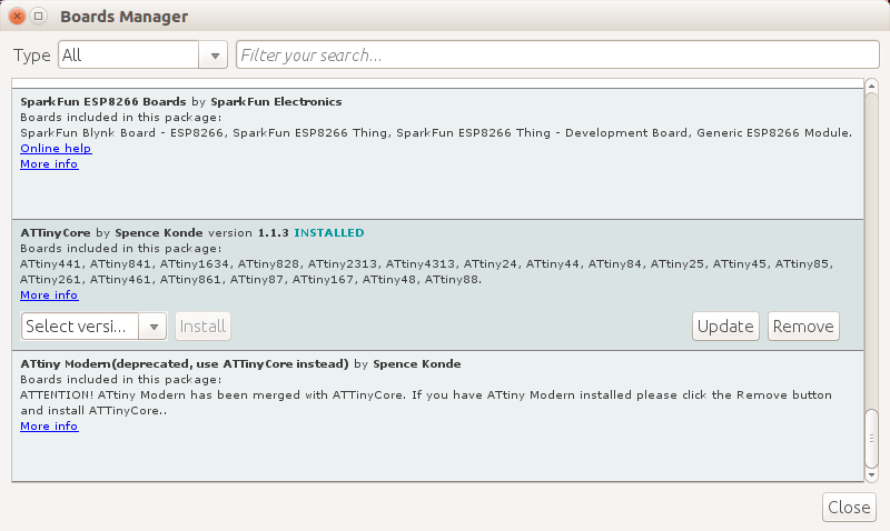
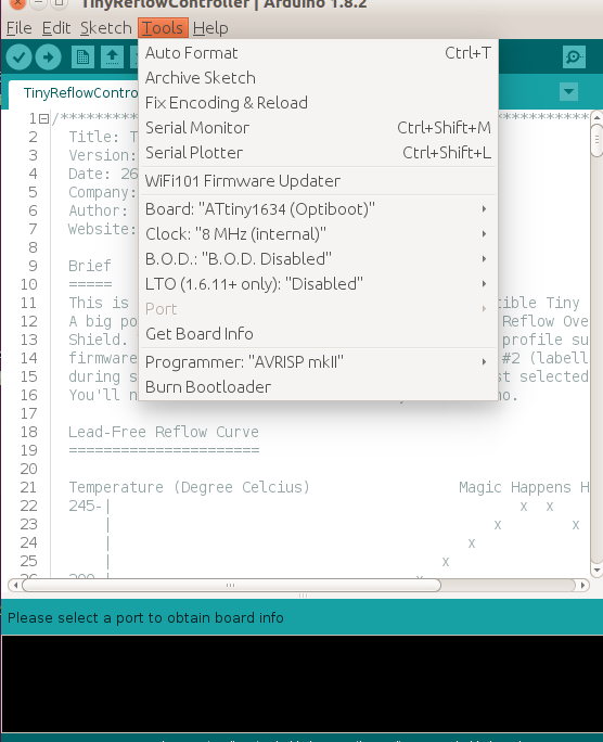
The board provides a standard FTDI (or compatible) USB-serial 6-pin breakout which can be used to upload firmware to the onboard mcu. This can done through the Arduino IDE. The on-board ATtiny1634R microcontroller uses the ATtinyCore written by Spence Konde. All you have to do is to install the ATtinyCore through the Arduino IDE Boards Manager. Prior to this you will have to burn ATtinyCore bootloader to the mcu. You can use an AVRISP mkII (or any of the AVR programmer supported on the IDE) to program the bootloader onto the ATtiny1634R. To program the bootloader, you connect the standard 6-pin AVR ISP (2×3 pins 2.54 mm) to the AVRISP mkII programmer. Then you hit “burn bootloader” after selecting the correct board option. Once the bootloader is in, then you can use the FTDI USB-serial to upload code normally from Arduino IDE.
Once the ATtinyCore board package has been installed, you should select ATtiny1634 (Optiboot) with the 8 MHz internal clock:
Demo
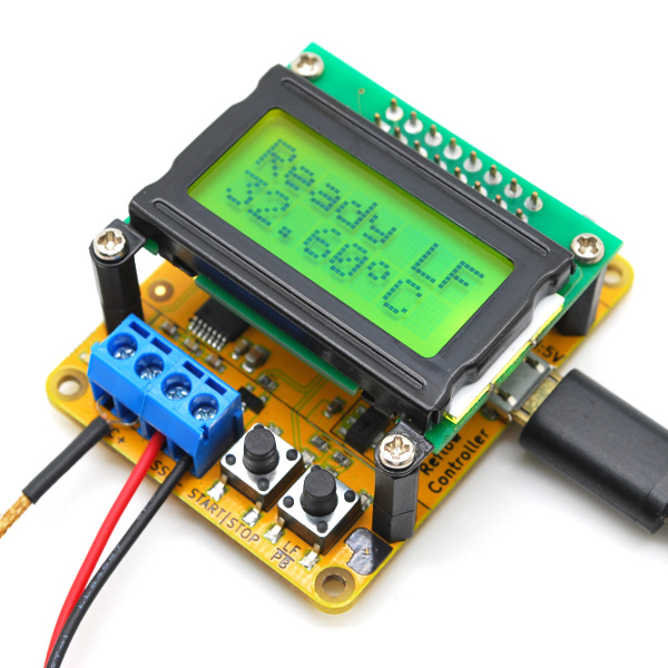
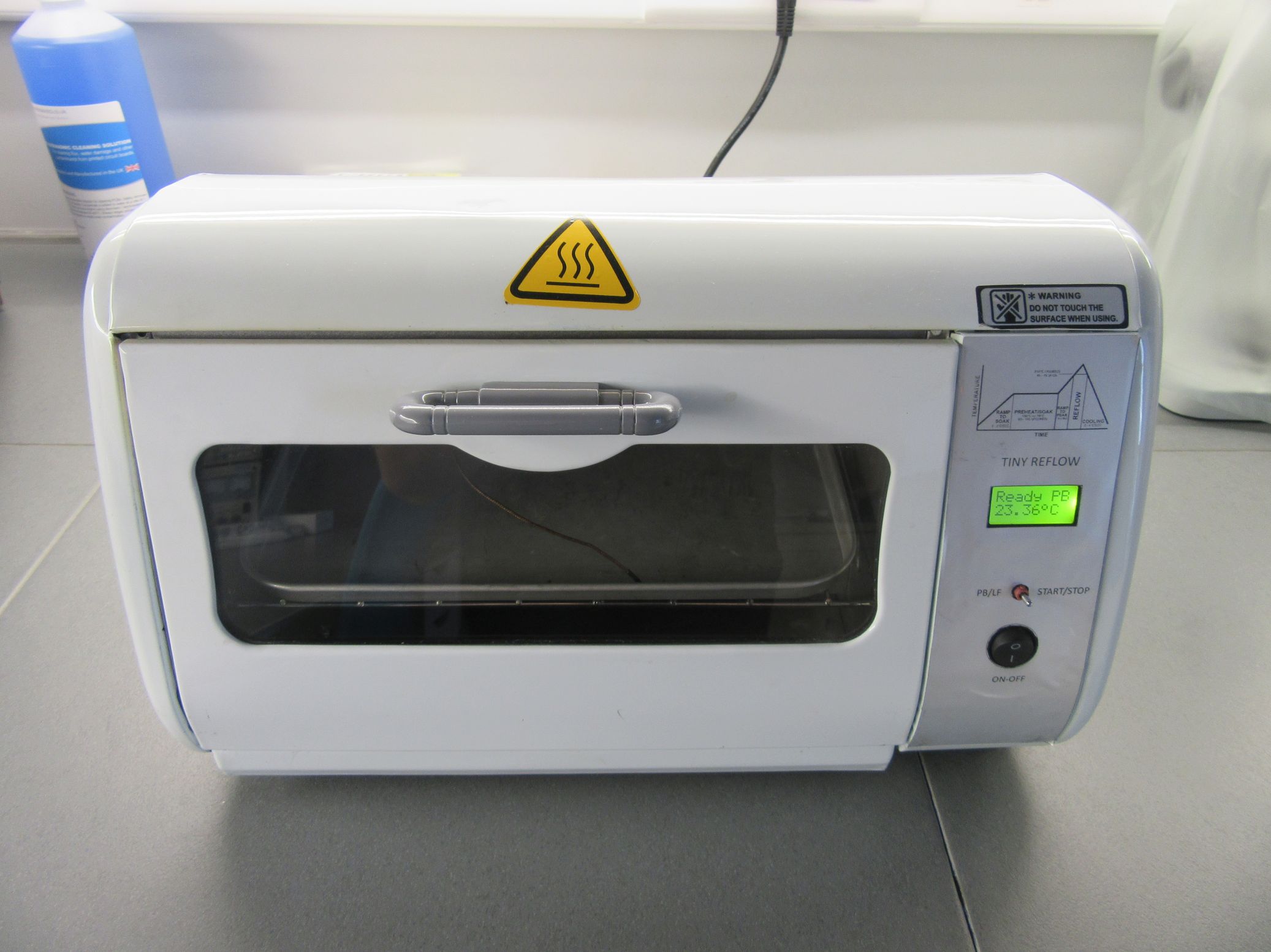
The PCB version of the reflow controller comes with an FTDI interface through which it can be programmed so if you are building on a breaboard, ensure you make provision for that too. Using a FTDI to USB Cable, connect the setup to your computer. Select the board type and upload the code to it. With this done, you can now connect your tiny reflow oven controller to your oven and power it on. You should see the splash come up with a screen similar to the image below.
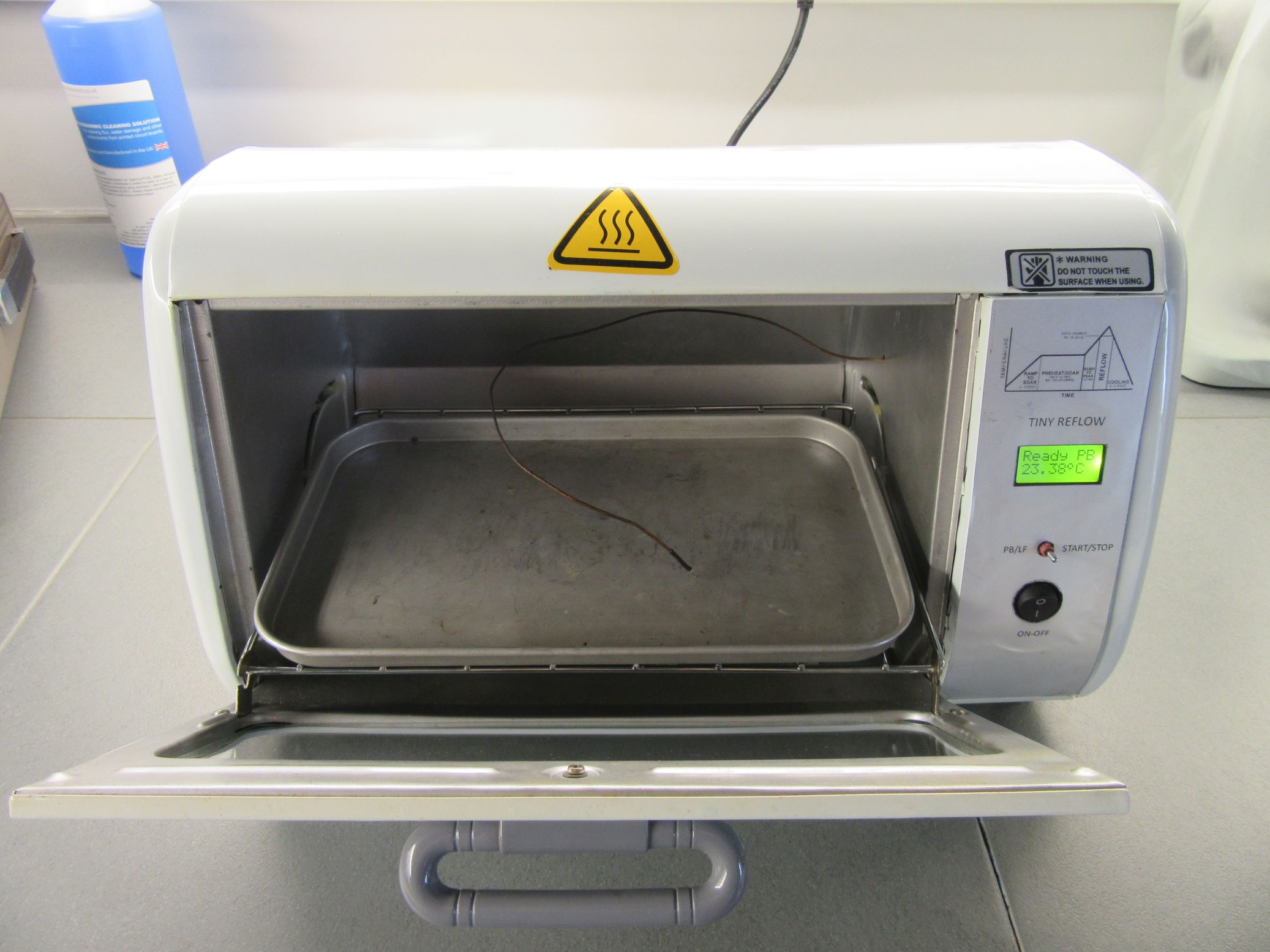
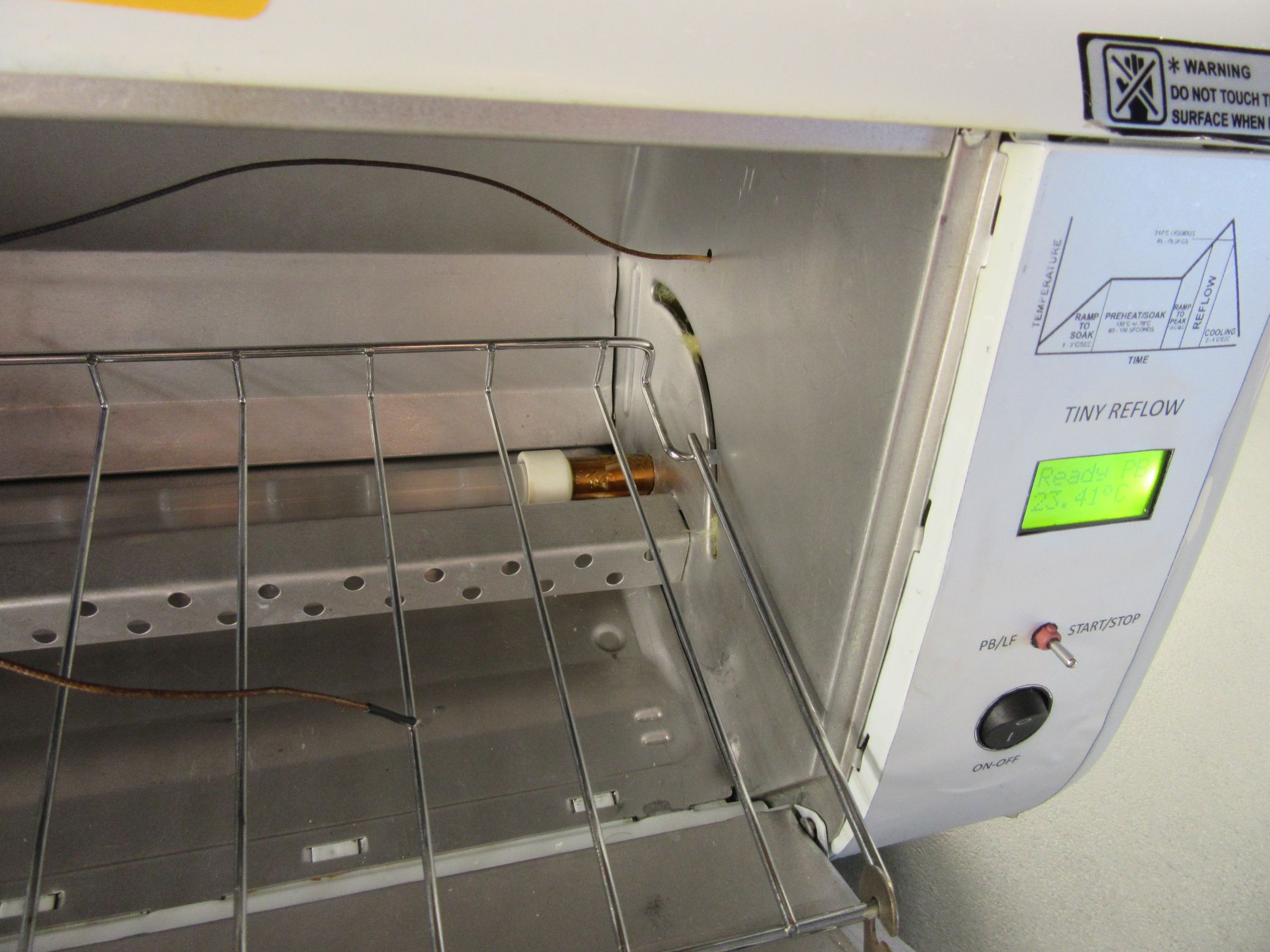
Installation on the mini Oven
We have installed the Tiny Reflow controller v1 on our small modified oven. This was a small 600W oven with analog dials and thermostat and we added insulation and two additional heating elements of 300W each. So total power is now 1200W. This makes the oven more powerfull and it is now able to reach desired temperature easier than with the 600W heating elements. You can see the different of the 600W and 1200W performance on the following graphs.
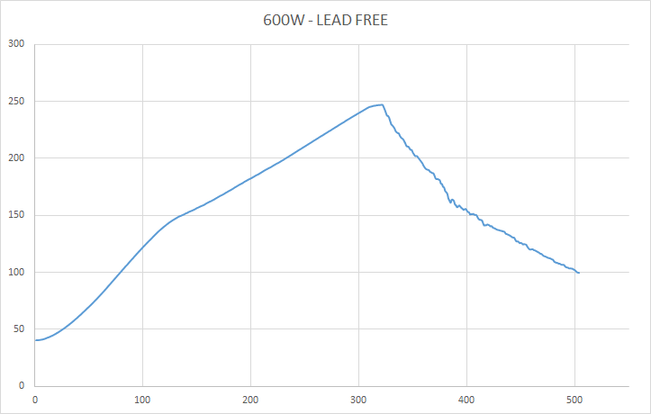
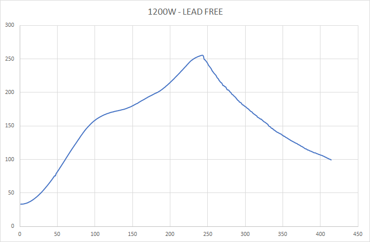
Reflow Results
The Tiny Reflow provides some statistics on it’s RS-232 output. Use any serial terminal program at 115200 bps 8N1 configuration to collect the temperature information across time. Two plots of the reflow profiles are shown below. The first is before modifying and insulating the oven (600W) and the second if for the 1200W modified oven. As you can see on the second graph the total reflow time was about 415 sec while the first graph shows 500 sec. Also you can notice that the 1200W reflow profile achieved a better preheat temperatre slope than the 600W that means it reached the desired temperature more easily. The 600W oven was strungling to do.
Demo Video
Conclusion
You can go through this list curated by Rocket Stream to get suggestions on the best kind of ovens to use with the tiny reflow controller or visit their eshop to purchase an already assembled and tested board.
That’s it for today’s tutorial. Thanks for reading. As usual, feel free to reach out to me via the comment section if you have any question about the project and also let me know if you made one following this guide.