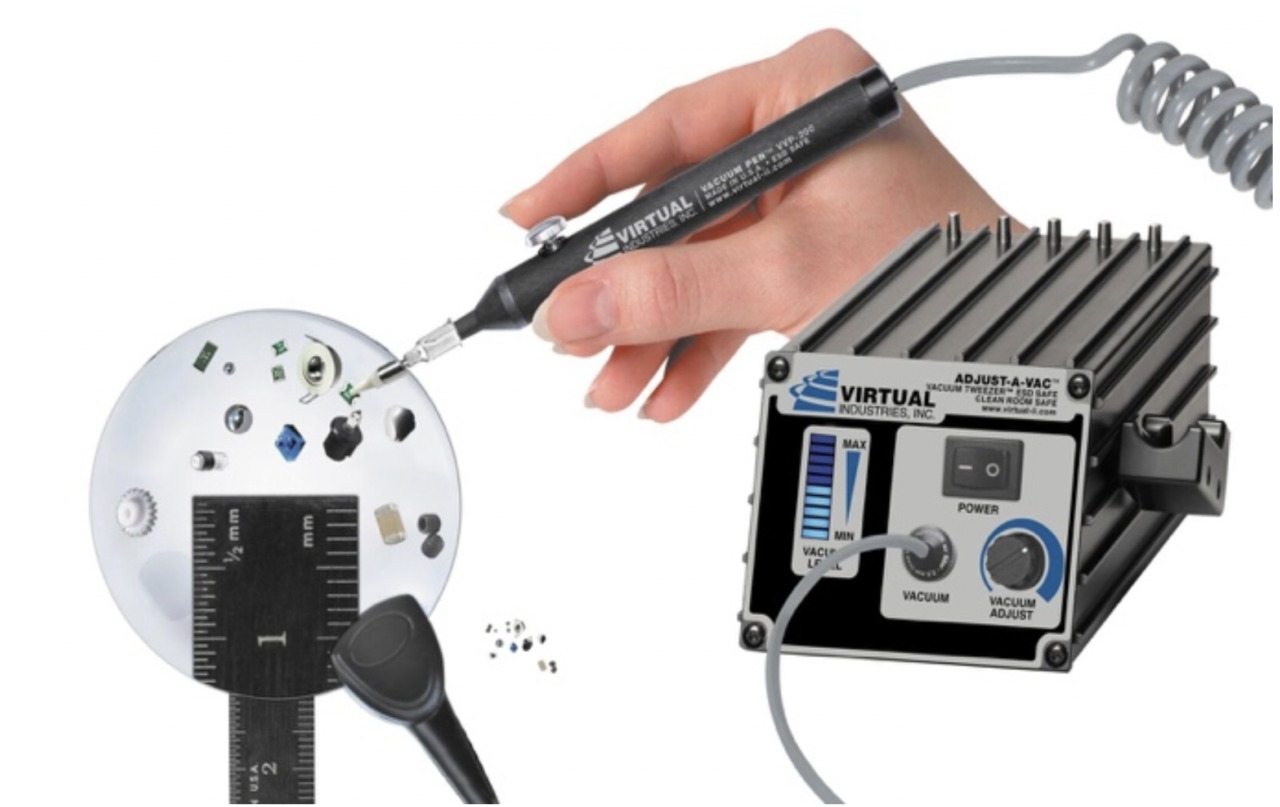
Virtual Industries Inc., a leading supplier of manual vacuum handling solutions, is pleased to introduce the new ADJUST-A-VAC™ AUTO-SHUT-OFF ESD-SAFE Kit with Buna-N Static Dissipative Non-Marking Vac (AV-6000A-110). A new series of VACUUM TWEEZER™ kits has been added to the Virtual Industries product line with an AUTO-SHUT-OFF feature. The new sensor turns on and off the ADJUST-A-VAC, helping users to be more productive, save energy, and extend life of the unit.
Now, when users turn the power switch to the AUTO position, the unit will be off. When you pick up the vacuum pen from its holder, the blue LED vacuum level bar will glow to show power is on.
The ADJUST-A-VAC ESD Safe Kit with ESD Safe Delrin Small Parts Tips and ESD-Safe Vacuum Tips allows the operator to adjust the vacuum level from just below atmospheric pressure to up to ten inches of mercury depending on the fragility of the part being handled. The vacuum tweezer system was developed as a result of customer concerns about manual handling of very thin/delicate substrates, wafers, MEMS devices and other very fragile components.
An integrated ten segment bar-graph-display visibly shows the vacuum level present during handling operations. The bar graph will show minimum vacuum level until a part is grasped and then the blue LED bar graph displays the vacuum level presented to the part being handled. Additionally, the vacuum port integrates a user replaceable inlet filter that protects operation of the tool from dust particles – the filter part number to order is VF-40M-5. Kits are available in 110 or 220 volt operation.
For more information about any of Virtual Industries’ advanced equipment, visit www.virtual-ii.com.
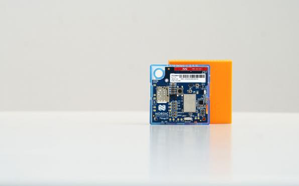
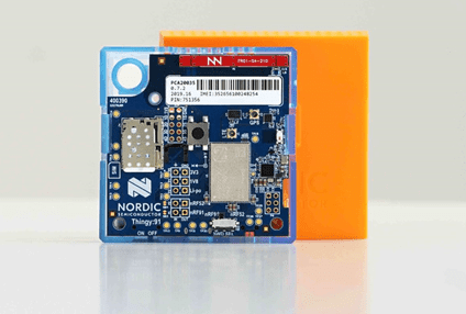
Based on Nordic’s industry-leading nRF9160 SiP multimode LTE-M/NB-IoT module with GPS, which uniquely supports Arm TrustZone Internet-grade encryption and security, the battery-powered Nordic Thingy:91 is a simplified rapid prototyping platform designed specifically for cellular IoT. It includes a full asset tracking sample application, an exhaustive list of nine sensors, ‘straight-out-of-the-box’ operation, and support for a full range of complementary short-range wireless technologies including Bluetooth 5 and NFC courtesy of Nordic’s flagship nRF52840 SoC.
Nordic Semiconductor announces the introduction of the ‘Thingy:91’ rapid cellular IoT prototyping platform which is certified for global, low-power, long-range LTE-M/NB-IoT applications, has unique Arm TrustZone security, includes a full range of sensors (see below), plus embedded support courtesy of a Nordic nRF52840 advanced multiprotocol System-on-Chip (SoC) for complementary ultra low power short-range wireless technologies such as Bluetooth®5, Thread, Zigbee, and ANT.
A Nano (4FF) eSIM card from iBasis preloaded with 10MB of data is bundled with the Thingy:91 to enable automatic, instant, out-of-the-box cellular LTE-M and NB-IoT connectivity and roaming in a long and growing list of countries with cellular IoT networks.
A prime application for the Thingy:91 is asset tracking, especially as it ships with a full sample asset-tracking application in place. This could take the form of shipping containers where individual items within the container can be tracked via short-range Bluetooth 5 (e.g. location within container and temperature for cold storage goods), with the container itself and any important changes in the status of its contents tracked remotely via long-range cellular wireless technology.
The Nordic Thingy:91 is housed in a 6 x 6-cm plastic and rubber case which includes a USB connector to charge the device’s 1440 mAh rechargeable Li-ion battery. The Thingy:91’s sensor list includes environmental sensors for measuring temperature, humidity, air quality, and air pressure, plus a color and light sensor, along with separate low-power and additional high G-force accelerometers.
Over the past few tutorials, we have explored different projects that involve building GUI interfaces and menu on the Nokia 5110 LCD display. For today’s tutorial, we will do something similar to that but we will kick it up a notch by introducing a GSM module which will help us put a range of GSM based options in the menu.
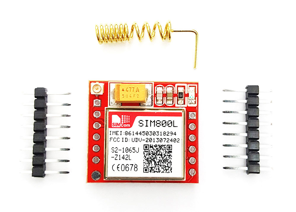
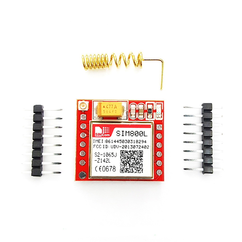
At the center 0f, today’s project is the SIM800l GSM/GPRS Module. This module is a miniature GSM modem, which can be integrated into a great number of IoT projects. The module can be used to achieve anything you can do with a normal feature phone, including sending SMS/text messages, make or receive phone calls, connecting to the internet through GPRS, TCP/IP, among others. In addition to this, the module supports quad-band GSM/GPRS network and can be controlled via microcontrollers or processors over serial communication, as such, it should work wherever you are in the world and should work with whichever microcontroller you choose to use it with.
Aside the SIM800l, we will also use the Nokia 5110 LCD Display, 3 pushbuttons, and an Arduino Pro Micro. The Nokia 5110 LCD will be used to display all the options associated with the project, providing visual feedback to the user when scrolling through them while the pushbuttons will be used to move up and down through the menu and make a selection when desired. The Arduino Micro, on the other hand, will serve as the brain for the project. It processes the inputs from the pushbuttons and determines what is displayed on the screen.
SIM800L GSM module with Nokia 5110 LCD and Arduino – [Link]
Over the past few tutorials, we have explored different projects that involve building GUI interfaces and menu on the Nokia 5110 LCD display. For today’s tutorial, we will do something similar to that but we will kick it up a notch by introducing a GSM module which will help us put a range of GSM based options in the menu.
SIM800L Quad-band Network Mini GPRS GSM module
At the center of, today’s project is the SIM800l GSM/GPRS Module. This module is a miniature GSM modem, which can be integrated into a great number of IoT projects. The module can be used to achieve anything you can do with a normal feature phone, including sending SMS/text messages, make or receive phone calls, connecting to the internet through GPRS, TCP/IP, among others. In addition to this, the module supports quad-band GSM/GPRS network and can be controlled via microcontrollers or processors over serial communication, as such, it should work wherever you are in the world and should work with whichever microcontroller you choose to use it with.
Aside the SIM800L, we will also use the Nokia 5110 LCD Display, 3 pushbuttons, and an Arduino Pro Micro. The Nokia 5110 LCD will be used to display all the options associated with the project, providing visual feedback to the user when scrolling through them while the pushbuttons will be used to move up and down through the menu and make a selection when desired. The Arduino Micro, on the other hand, will serve as the brain for the project. It processes the inputs from the pushbuttons and determines what is displayed on the screen.
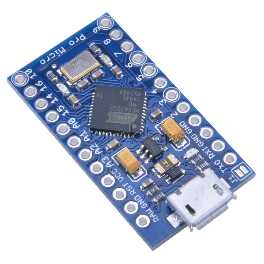
Arduino Pro Micro board
The Arduino pro micro is based on the Atmega32u4 microcontroller and while it is similar to the Arduino Pro Mini, this singular point makes all the difference. The ProMicro possesses an onboard USB transceiver inside the 32U4, which removes the need for a bulky external USB interface and also has a voltage regulator on-board which means it can accept up to 12V DC., although if supplying unregulated power, you need to connect to “RAW”, not “VCC”. The Pro Micro has the same GPIO pins as the Arduino Leonardo and can be used in a project where smaller, easy to program boards are required.
At the end of today’s project, you will know some of the basic commands required to send data from Arduino to a webpage using a GSM module, receiving data from a webpage and generally using the SIM800 GSM Module with Arduino. File request, Network info, Weather info, Location info, Save location, Upload location, Auto Upload, Connect, Disconnect, Lightswitch, Power-down, Reset all these are enabled using the SIM800L
Required Component
The following component is required for this project;
Arduino Pro Micro
Sim800l
Nokia 5110 LCD Display
Pushbuttons (3)
2n222
Jumper Wires
Breadboard
Each of these components can be bought from different electronics component websites. The Pro Micro was used basically because it is cheap and because it’s high speed as such, if these are not a requirement, you can also decide to use an Arduino Uno or any other Arduino board for the project. However, ensure you pay attention on how this change could affect the code for the project.
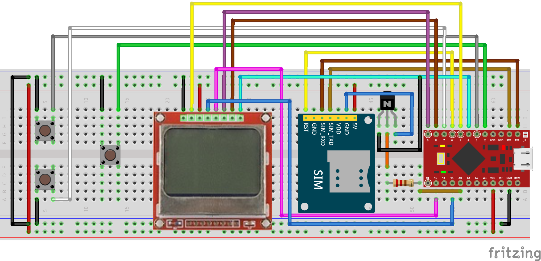
Schematics
The schematics for this project is quite straight forward with the only element that may be difficult to follow is the connection of the Pushbuttons without pull-ups or pull-down resistors. These were done to reduce the number of components used for the project, as such, the internal pull-ups of the Arduino digital pins will be used such that the digital pin is driven LOW when the push button is pressed.
Connect the component as shown in the schematics below.
Schematics
A pin to pin map showing how the components are connected to the Arduino is described below;
To learn more about connecting the Nokia 5110 LCD to Arduino and some of the other cool things that you can do using the display, you can check some of our past tutorials here.
With all the components connected, go over it one more time to ensure everything is as it should be.
Code
The code for these project is quite simple as mentioned in the introduction, we will create a menu on the display that will allow us to control the device and perform all the functions mentioned in the introduction.
To reduce the amount of code we need to write, we will use quite a number of libraries including; the EEPROM Library, the AVR library, the Adafruit_GFX Library, and the Adafruit_PCD8544 library. While the EEPROM and AVR libraries come preloaded on the Arduino IDE, the Adafruit_GFX and PCD8544 libraries will need to be installed via the Arduino library manager or downloaded from the links attached to them and installed. The EEPROM Library will be used to store the weather information and location data pulled from the server, while the AVR library will be used to implement several low power features for the project. The Adafruit_GFX and PCD8544 libraries, on the other hand, will be used to reduce the amount of work required to talk to communicate with the display.
As usual, I will do a run through the code and explain as much of it as possible.
Like always, we start the code by including the libraries that are required for the project.
Next, we declare the pins of the Arduino to which the pins of the other components are connected with descriptive names that help us understand with each pin stands for. Also, create a variable which will be used to hold different values for the project.
#define lcdBL 5 // LCD backlight pin
#define resetPin 6 // Reset pin of Sim800L
#define pwrPin A0 // controling an NPN transistor that provides 0V to GND pin of Sim800L
#define btnEnt 2
#define btnUp 3
#define btnDwn 7
#define MENU_ROW_HEIGHT 11
#define LCD_ROWS 5
#define COUNTER 2550 // auto upload sleep counter will make the device sleep for 6 hours (COUNTER * 1.059 * 8 seconds)
Next, we create an object of the Adafruit PCD8544 library and a few other variables.
Adafruit_PCD8544 display = Adafruit_PCD8544(9, 8, 4);
unsigned long startMillis, currentMillis;
const unsigned long period PROGMEM = 30000; // The duration in milliseconds before the microcontroller goes to sleep
bool GPRSCon, isItSleep, exitBool;
byte menuPos, menuScreen, markerPos, menuStartAt;
const char* const menu[13] PROGMEM = {"File Request", "Network Info", "Weather Info", "Location Info", "Save Location",
"Last Saved" , "Upload Loc", "Auto Upload", "Connect", "Disconnect",
"Light Switch", "Power Down", "Reset Sim800L"
};
byte MENU_LENGTH = sizeof(menu) / sizeof(menu[0]);
Next, we move to the void setup() function.
We start by declaring the pin mode of each of the pins and activating the Arduino built-in pull up resistors on the pins to which the buttons are connected.
Next, we initialize the display, flipping it to the desired orientation and clearing it so it is blank.
display.begin();
display.setRotation(2); // My screen is flipped upside down! :/
display.clearDisplay();
delay(4000); // You may increase this if the duration isn't enough
Next, we use a while loop to check the state of the SIM800L and display the debug information. If it is turned off or not responding, the command resetSim800() is called to restart the GSM module.
while (!checkSim800()) {
display.clearDisplay();
display.println(F("Sim800L is \nturned off or \nnot responding"));
display.display();
delay(2000);
resetSim800();
}
With this done, the waitToReg() function is called to allow the GSM module to connect to a network before proceeding. The menu containing all the functions we will be demonstrating is then displayed on the screen and the millis() is recorded as the variable startmillis. This will be used to estimate how much time has passed later on in the device operations.
The void loop function is charged with detecting if any of the buttons are pressed and depending on the button that is pressed and the current position of the menu, take actions in line with the functions of the project.
The function starts with an “if” function that checks if the push button representing button-down is has been pressed. If yes, the button checks if the menu is at its end and if it’s not, it increases the position by one and refreshes the display. If it is at its end, the position is set to the beginning.
The same is done if the btnup variable representing the pushbutton that is pressed.
Next, the push button designated as “enter” is read via the isButtonDown() function. If yes, this, via a series of if statements, takes into account the current position of the menu using the “menuPos” variable and determines the action to be performed based on the function of the project. For example, if the “menuPos” variable is equal to 3, the locinfo(0) function is called and the menu is displayed after the function has run its course. The if…else if… function is used to check all the possible menu position and call the right functions.
void loop() {
currentMillis = millis();
if (isButtonDown(btnDwn) == true) {
if (menuPos < MENU_LENGTH - 1) {
menuPos++;
if (menuPos - menuStartAt > 3 )
menuStartAt++;
showMenu();
}
delay(100);
startMillis = currentMillis;
}
if (isButtonDown(btnUp) == true) {
if (menuPos > 0) {
menuPos--;
if (menuPos - menuStartAt < 0 && menuStartAt != 0)
menuStartAt--;
showMenu();
}
delay(100);
startMillis = currentMillis;
}
if (isButtonDown(btnEnt) == true) {
if (menuPos == 0) {
String s = openURL(F("raw.githubusercontent.com/HA4ever37/Sim800l/master/Sim800.txt"), true); // Change the URL to your text file link
if (s == "ERROR" || s == "") {
display.clearDisplay();
display.println(F("Bad request! \ntry again"));
display.display();
delay(2000);
}
else {
s = s.substring(s.indexOf('\r') + 2, s.lastIndexOf("OK"));
s = s.substring(s.indexOf('\r') + 2, s.length() - 1);
display.clearDisplay();
digitalWrite(lcdBL, LOW);
/*for (byte i = 0; i < s.length(); i++) {
//Serial.print(s.charAt(i));
display.print(s.charAt(i));
}*/
display.print(s);
display.display();
digitalWrite(lcdBL, HIGH);
delay(500);
digitalWrite(lcdBL, LOW);
while (!isButtonDown(btnEnt) && !isButtonDown(btnUp) && !isButtonDown(btnDwn));
}
showMenu();
}
else if (menuPos == 1) {
netInfo();
showMenu();
}
else if (menuPos == 2) {
const String s = openURL(locInfo(3), false);
char split = '"';
int pos = s.indexOf(F("description\":\"")) + 14;
String weather = s.substring(pos, s.indexOf(split, pos));
weather[0] = toupper(weather[0]);
display.clearDisplay();
display.println(weather);
split = ',';
pos = s.indexOf(F("temp\":")) + 6;
display.print(F("Temp:"));
display.print(s.substring(pos, s.indexOf(split, pos)));
display.println(F(" C"));
pos = s.indexOf(F("p_min\":")) + 7;
display.print(F("Min:"));
display.print(s.substring(pos, s.indexOf(split, pos)));
display.println(F(" C"));
split = '}';
pos = s.indexOf(F("p_max\":")) + 7;
display.print(F("Max:"));
display.print(s.substring(pos, s.indexOf(split, pos)));
display.println(F(" C"));
split = ',';
pos = s.indexOf(F("humidity\":")) + 10;
display.print(F("Humidity:"));
display.print(s.substring(pos, s.indexOf(split, pos)));
display.println(F("%"));
pos = s.indexOf(F("speed\":")) + 7;
display.print(F("Wind:"));
display.print(s.substring(pos, s.indexOf(split, pos)));
//display.print(s.substring(s.indexOf(F("speed\":")) + 7, s.indexOf(F(",\"deg"))));
display.print(F(" m/s"));
display.display();
while (!isButtonDown(btnEnt) && !isButtonDown(btnUp) && !isButtonDown(btnDwn));
showMenu();
}
else if (menuPos == 3) {
locInfo(0);
showMenu();
}
else if (menuPos == 4) {
locInfo(2);
showMenu();
}
else if (menuPos == 5) {
readEeprom();
showMenu();
}
else if (menuPos == 6) {
locInfo(1);
showMenu();
}
else if (menuPos == 7)
autoUp();
else if (menuPos == 8) {
connectGPRS();
showMenu();
}
else if (menuPos == 9) {
disConnectGPRS();
showMenu();
}
else if (menuPos == 10)
toggle();
else if (menuPos == 11)
pwrDown();
else if (menuPos == 12) {
resetSim800();
showMenu();
}
delay(100);
startMillis = currentMillis = millis();
}
if (currentMillis - startMillis >= period)
pwrDown();
}
Next up are the codes, for each of the functions called under the setup() and void loop() functions. The codes are well commented and should be studied to better understand how each of the functions work. If you get stuck trying to figure out what any part of it does, feel free to reach out to me via the comment section.
The complete code for the project is available below and also attached under the download section of the tutorial.
#include <EEPROM.h>
#include <avr/sleep.h>
#include <avr/power.h>
#include <avr/wdt.h>
#include <Adafruit_GFX.h>
#include <Adafruit_PCD8544.h>
#define lcdBL 5         // LCD backlight pin
#define resetPin 6      // Reset pin of Sim800L
#define pwrPin A0       // controling an NPN transistor that provides 0V to GND pin of Sim800L
#define btnEnt 2
#define btnUp 3
#define btnDwn 7
#define MENU_ROW_HEIGHT 11
#define LCD_ROWS 5
#define COUNTER 2550   // auto upload sleep counter will make the device sleep for 6 hours (COUNTER * 1.059 * 8 seconds)
Adafruit_PCD8544 display = Adafruit_PCD8544(9, 8, 4);

unsigned long startMillis, currentMillis;
const unsigned long period PROGMEM = 30000; // The duration in milliseconds before the microcontroller goes to sleep
bool GPRSCon, isItSleep, exitBool;
byte menuPos, menuScreen, markerPos, menuStartAt;
const char* const menu[13] PROGMEM  = {"File Request", "Network Info", "Weather Info", "Location Info", "Save Location",
                                       "Last Saved" , "Upload Loc", "Auto Upload", "Connect", "Disconnect",
                                       "Light Switch", "Power Down", "Reset Sim800L"
                                      };
byte MENU_LENGTH =  sizeof(menu) / sizeof(menu[0]);
void setup() {
  pinMode(btnUp, INPUT_PULLUP);
  pinMode(btnDwn, INPUT_PULLUP);
  pinMode(btnEnt, INPUT_PULLUP);
  pinMode(lcdBL, OUTPUT);
  pinMode(resetPin, OUTPUT);
  pinMode(pwrPin, OUTPUT);
digitalWrite(resetPin, HIGH);
digitalWrite(resetPin, HIGH);
digitalWrite(pwrPin, HIGH);
digitalWrite(lcdBL, LOW);
display.begin();
  display.setRotation(2);     // My screen is flipped upside down! :/
  display.clearDisplay();
  delay(4000);  // You may increase this if the duration isn't enough
while (!checkSim800()) {
    display.clearDisplay();
    display.println(F("Sim800L is \nturned off or \nnot responding"));
    display.display();
    delay(2000);
    resetSim800();
  }
  waitToReg();
  showMenu();
  startMillis = millis();
}
void loop() {
  currentMillis = millis();
  if (isButtonDown(btnDwn) == true) {
    if (menuPos < MENU_LENGTH - 1) {
      menuPos++;
      if (menuPos - menuStartAt > 3 )
        menuStartAt++;
      showMenu();
    }
    delay(100);
    startMillis = currentMillis;
  }
  if (isButtonDown(btnUp) == true) {
    if (menuPos > 0) {
      menuPos--;
      if (menuPos - menuStartAt < 0 && menuStartAt != 0)
        menuStartAt--;
      showMenu();
    }
    delay(100);
    startMillis = currentMillis;
  }
if (isButtonDown(btnEnt) == true) {
if (menuPos == 0) {
String s = openURL(F("raw.githubusercontent.com/HA4ever37/Sim800l/master/Sim800.txt"), true); // Change the URL to your text file link
if (s == "ERROR" || s == "") {
display.clearDisplay();
display.println(F("Bad request! \ntry again"));
display.display();
delay(2000);
}
else {
s = s.substring(s.indexOf('\r') + 2, s.lastIndexOf("OK"));
s = s.substring(s.indexOf('\r') + 2, s.length() - 1);
display.clearDisplay();
digitalWrite(lcdBL, LOW);
/*for (byte i = 0; i < s.length(); i++) {
//Serial.print(s.charAt(i));
display.print(s.charAt(i));
}*/
display.print(s);
display.display();
digitalWrite(lcdBL, HIGH);
delay(500);
digitalWrite(lcdBL, LOW);
while (!isButtonDown(btnEnt) && !isButtonDown(btnUp) && !isButtonDown(btnDwn));
}
showMenu();
}
else if (menuPos == 1) {
netInfo();
showMenu();
}
else if (menuPos == 2) {
const String s = openURL(locInfo(3), false);
char split = '"';
int pos = s.indexOf(F("description\":\"")) + 14;
String weather = s.substring(pos, s.indexOf(split, pos));
weather[0] = toupper(weather[0]);
display.clearDisplay();
display.println(weather);
split = ',';
pos = s.indexOf(F("temp\":")) + 6;
display.print(F("Temp:"));
display.print(s.substring(pos, s.indexOf(split, pos)));
display.println(F(" C"));
pos = s.indexOf(F("p_min\":")) + 7;
display.print(F("Min:"));
display.print(s.substring(pos, s.indexOf(split, pos)));
display.println(F(" C"));
split = '}';
pos = s.indexOf(F("p_max\":")) + 7;
display.print(F("Max:"));
display.print(s.substring(pos, s.indexOf(split, pos)));
display.println(F(" C"));
split = ',';
pos = s.indexOf(F("humidity\":")) + 10;
display.print(F("Humidity:"));
display.print(s.substring(pos, s.indexOf(split, pos)));
display.println(F("%"));
pos = s.indexOf(F("speed\":")) + 7;
display.print(F("Wind:"));
display.print(s.substring(pos, s.indexOf(split, pos)));
//display.print(s.substring(s.indexOf(F("speed\":")) + 7, s.indexOf(F(",\"deg"))));
display.print(F(" m/s"));
display.display();
while (!isButtonDown(btnEnt) && !isButtonDown(btnUp) && !isButtonDown(btnDwn));
showMenu();
}
else if (menuPos == 3) {
locInfo(0);
showMenu();
}
else if (menuPos == 4) {
locInfo(2);
showMenu();
}
else if (menuPos == 5) {
readEeprom();
showMenu();
}
else if (menuPos == 6) {
locInfo(1);
showMenu();
}
else if (menuPos == 7)
autoUp();
else if (menuPos == 8) {
connectGPRS();
showMenu();
}
else if (menuPos == 9) {
disConnectGPRS();
showMenu();
}
else if (menuPos == 10)
toggle();
else if (menuPos == 11)
pwrDown();
else if (menuPos == 12) {
resetSim800();
showMenu();
}
delay(100);
startMillis = currentMillis = millis();
}
if (currentMillis - startMillis >= period)
pwrDown();
}
void waitToReg() {
display.clearDisplay();
display.println(F("Waiting to \nregister sim \ncard"));
display.display();
do {
Serial.print(F("AT+COPS?\r"));
} while (Serial.readString().indexOf(F("+COPS: 0,0,\"")) == -1);
}
String openURL(String string, bool ssl) {
while (!GPRSCon)
connectGPRS();
display.clearDisplay();
Serial.print(F("AT+HTTPINIT\r"));
display.println(F("HTTP \nIntialization\n"));
display.display();
if (Serial.readString().indexOf(F("OK")) == -1)
return "";
Serial.print(F("AT+HTTPPARA=\"CID\",1\r"));
Serial.readString();
display.print(F("Sending URL\nrequest"));
display.display();
Serial.print(F("AT+HTTPPARA=\"URL\",\""));
Serial.print(string + "\"\r");
if (Serial.readString().indexOf(F("OK")) == -1)
return "";
display.print(Serial.readString());
display.display();
display.clearDisplay();
Serial.print(F("AT+HTTPPARA=\"REDIR\",1\r"));
Serial.readString();
if (ssl) {
Serial.print(F("AT+HTTPSSL=1\r"));
Serial.readString();
}
else {
Serial.print(F("AT+HTTPSSL=0\r"));
Serial.readString();
}
Serial.print(F("AT+HTTPACTION=0\r"));
Serial.readString();
while (!Serial.available());
Serial.readString();
if (Serial.readString().indexOf(F(",200,")) != -1)
return "";
display.print(F("Downloading \ndata"));
display.display();
Serial.print(F("AT+HTTPREAD\r"));
string = Serial.readString();
string.trim();
Serial.print(F("AT+HTTPTERM\r"));
Serial.readString();
return string;
}
String locInfo(byte save) {
while (!GPRSCon)
connectGPRS();
display.clearDisplay();
display.println(F("Getting\nlocation info\n"));
display.display();
Serial.print(F("AT+CIPGSMLOC=1,1\r"));
Serial.readString();
while (!Serial.available());
String s = Serial.readString();
if (s.indexOf(',') == -1) {
display.println(F("Failed to \nget info!"));
display.display();
delay(2000);
}
else {
s = s.substring(s.indexOf(',') + 1, s.indexOf("OK"));
s.trim();
String data[4];
for (byte i = 0; i < 4; i++) {
data[i] = s.substring(0, s.indexOf(','));
s = s.substring(s.indexOf(',') + 1, s.length());
}
if (save == 0) {
display.clearDisplay();
display.print(F("Dt:"));
display.println(data[2]);
display.print(F("Time:"));
display.println(data[3]);
display.println(F("Latitude: "));
display.println(data[1]);
display.println(F("Longitude: "));
display.println(data[0]);
display.display();
while (!isButtonDown(btnEnt) && !isButtonDown(btnUp) && !isButtonDown(btnDwn));
}
else if (save == 1) {
display.print(F("Connecing to\nupload server"));
display.display();
display.clearDisplay();
s = "{\"Date\": \"" + data[2] + "\", \"Time\": \"" + data[3] + "\", \"Location link\": \"www.google.com/maps?q=" + data[1] + "," + data[0] + "\"}";
Serial.print(F("AT+HTTPINIT\r"));
Serial.readString();
Serial.print(F("AT+HTTPPARA=\"CID\",1\r"));
Serial.readString();
Serial.print(F("AT+HTTPSSL=0 \r"));
Serial.readString();
Serial.print(F("AT+HTTPPARA=\"URL\",\"api.jsonbin.io/b\"\r"));
Serial.readString();
Serial.print(F("AT+HTTPPARA=\"CONTENT\",\"application/json\"\r"));
Serial.readString();
// WARNING!!! YOU MUST CHANGE the secret-key otherwise your location info will be sent to my JSON account!
Serial.print(F("AT+HTTPPARA=\"USERDATA\",\"secret-key: $2a$10$/4cwS1j8JzAgdbYKEDbeM.x19a0UM5C612PtEvoBv.hqtGagcY.DG\\r\\nprivate: true\"\r"));
Serial.readString();
Serial.print(F("AT+HTTPDATA="));
Serial.print(String(s.length()) + ",2000\r");
Serial.readString();
Serial.print(s + "\r");
Serial.readString();
Serial.print(F("AT+HTTPACTION=1\r"));
Serial.readString();
while (!Serial.available());
s = Serial.readString();
if (s.indexOf(F(",200,")) == -1 ) {
display.print(F("Failed to\nupload info!"));
display.display();
}
else {
display.println(F("Location \nuploaded!"));
display.display();
}
Serial.print(F("AT+HTTPREAD\r"));
Serial.readString();
Serial.print(F("AT+HTTPTERM\r"));
Serial.readString();
}
else if (save == 2) {
writeEeprom("Dt:" + data[2] + "\nTime:" + data[3] + "\nLongitude:\n" + data[0] + "\nLatitude:\n" + data[1]);
display.println(F("Info saved \nto Eeprom!:"));
display.display();
delay(2000);
}
else if (save == 3) {
s = F("api.openweathermap.org/data/2.5/weather?lon=");
s += data[0];
s += F("&lat=");
s += data[1];
s += F("&units=metric&appid=0a3456488cb52d167293ee9ca1f00539"); // Please change the App id to your API key
return s;
}
}
s = "";
return s;
}
void netInfo() {
if (isItSleep) {
wakeUp();
isItSleep = false;
}
display.clearDisplay();
display.println(F("Getting\nnetwork info"));
display.display();
String data[2];
String network;
do {
Serial.print(F("AT+COPS?\r"));
network = Serial.readString();
//Serial.println(network);
} while (network.indexOf(F("+COPS: 0,0,\"")) == -1);
network = network.substring(network.lastIndexOf(F(",\"")) + 2, network.lastIndexOf(F("\"")));
exitBool = false;
attachInterrupt(digitalPinToInterrupt(btnEnt), exitLoop, FALLING);
while (!exitBool) {
Serial.print(F("AT+CSQ\r"));
String quality = Serial.readString();
quality = quality.substring(quality.indexOf(F(": ")) + 2, quality.indexOf(F(",")));
if (quality.toInt() < 10)
quality = "Poor " + quality;
else if (quality.toInt() < 15)
quality = "Fair " + quality;
else if (quality.toInt() < 20)
quality = "Good " + quality;
else
quality = "Excellent " + quality;
Serial.print(F("AT+CCLK?\r"));
String s = Serial.readString();
char am_pm[] = "AM";
byte hrs = 12;
data[0] = s.substring(s.indexOf('\"') + 1, s.indexOf(','));
data[1] = s.substring(s.indexOf(',') + 1, s.indexOf('-'));
if (data[1].substring(0, 2).toInt() > hrs) {
am_pm[0] = 'P';
hrs = data[1].substring(0, 2).toInt() - hrs;
}
else if (data[1].substring(0, 2).toInt() == hrs)
am_pm[0] = 'P';
else if (data[1].substring(0, 2).toInt() == 0);
else if (data[1].substring(0, 2).toInt() < hrs)
hrs = data[1].substring(0, 2).toInt();
display.clearDisplay();
display.println(network);
display.println(F("Sig. Strength:"));
display.println(quality);
display.println(F("Date & Time:"));
display.print(F("20"));
display.println(data[0]);
display.println(String(hrs) + data[1].substring(2, data[1].length() ) + " " + am_pm);
display.display();
}
}
void exitLoop() {
if (isButtonDown(btnEnt)) {
detachInterrupt(btnEnt);
exitBool = true;
}
}
bool checkGPRS() {
Serial.print(F("AT+SAPBR=2,1\r"));
if (Serial.readString().indexOf(F("+SAPBR: 1,1,")) != -1)
return true;
return false;
}
void connectGPRS() {
if (isItSleep) {
wakeUp();
isItSleep = false;
}
if (checkGPRS()) {
display.clearDisplay();
display.println(F("Already \nconnected!"));
display.display();
delay(2000);
}
else {
display.clearDisplay();
display.println(F("Initializing \nSim800L\n"));
display.display();
Serial.print(F("AT+CSCLK=0\r"));
while (!Serial.available());
Serial.readString();
Serial.print(F("AT+SAPBR=3,1,\"APN\",\"pwg\"\r")); // Need to be changed to your APN
Serial.readString();
display.println(F("Trying to\nconnect to the\naccess point"));
display.display();
display.clearDisplay();
Serial.print(F("ATE0\r"));
Serial.readString();
Serial.print(F("AT+SAPBR=1,1\r"));
while (!Serial.available());
if (Serial.readString().indexOf(F("OK")) != -1) {
display.print(F("Connected!"));
GPRSCon = true;
}
else {
display.print(F("Failed to \nconnect!"));
display.display();
delay(1000);
resetSim800();
waitToReg();
}
Serial.print(F("ATE1\r"));
Serial.readString();
}
}
void disConnectGPRS() {
if (!checkGPRS()) {
display.clearDisplay();
display.println(F("Already \ndisconnected!"));
display.display();
delay(2000);
}
else {
display.clearDisplay();
display.print(F("Disconnecting \nGPRS"));
display.display();
Serial.print(F("AT+SAPBR=0,1\r"));
Serial.readString();
delay(100);
Serial.print(F("AT+CSCLK=2\r"));
Serial.readString();
GPRSCon = false;
}
}
void readEeprom() {
String s;
for (int i = 0; EEPROM.read(i) != 0 && i < EEPROM.length(); i++)
s += (char)EEPROM.read(i);
display.clearDisplay();
display.print(s);
display.display();
delay(100);
while (!isButtonDown(btnEnt) && !isButtonDown(btnUp) && !isButtonDown(btnDwn));
}
void writeEeprom(String s) {
for (int i = 0; i < s.length() && i < EEPROM.length(); i++) {
EEPROM.update(i, s.charAt(i));
}
}
void resetSim800() {
if (isItSleep) {
wakeUp();
isItSleep = false;
}
else {
display.clearDisplay();
display.println(F("Restarting"));
display.display();
digitalWrite(resetPin, LOW);
delay(100);
digitalWrite(resetPin, HIGH);
GPRSCon = false;
delay(2000);
waitToReg();
}
}
void autoUp() {
display.clearDisplay();
display.println(F("To disable \nautoupload\nplease restart\nthe device"));
display.display();
delay(3000);
while (true) {
if (isItSleep)
connectGPRS();
locInfo(1);
Serial.print(F("AT+CPOWD=0\r"));
Serial.readString();
digitalWrite(lcdBL, HIGH); // keep the LCD backlight off during sleep time and wakeups to reduce power consumption
display.clearDisplay();
display.display();
display.command( PCD8544_FUNCTIONSET | PCD8544_POWERDOWN);
digitalWrite(pwrPin, LOW);
savePower();
for (int i = 0; i < COUNTER; i++)
myWatchdogEnable (0b100001); // 8 seconds
//myWatchdogEnable (0b100000); // 4
sleep_disable();
power_all_enable();
display.begin();
isItSleep = true;
}
}
void toggle() {
if (isButtonDown(btnEnt))
digitalWrite(lcdBL, !digitalRead(lcdBL));
}
bool isButtonDown(byte pin) {
if (digitalRead(pin) == LOW) {
delay(30);
if (digitalRead(pin) == LOW)
return true;
return false;
}
return false;
}
void showMenu() {
for (byte i = menuStartAt; i < (menuStartAt + LCD_ROWS); i++) {
byte markerY = (i - menuStartAt) * MENU_ROW_HEIGHT;
if (i == menuPos) {
display.setTextColor(WHITE, BLACK);
display.fillRect(0, markerY, display.width(), MENU_ROW_HEIGHT, BLACK);
}
else {
display.setTextColor(BLACK, WHITE);
display.fillRect(0, markerY, display.width(), MENU_ROW_HEIGHT, WHITE);
}
if (i >= MENU_LENGTH)
continue;
display.setCursor(3, markerY + 2);
display.print((char*)pgm_read_word(&(menu[i])));
}
display.display();
}
bool checkSim800() {
Serial.begin(9600);
while (Serial.available() > 0)
Serial.read();
Serial.print(F("AT\r"));
delay(100);
if (Serial.available() > 0) {
Serial.read();
return true;
}
else
return false;
}
void wakeUp() {
digitalWrite(resetPin, HIGH);
digitalWrite(pwrPin, HIGH);
display.clearDisplay();
display.println(F("Waking up \nSim800L"));
display.display();
delay(4000);
while (!checkSim800()) {
display.clearDisplay();
display.println(F("Sim800L is \nturned off or \nnot responding"));
display.display();
delay(2000);
resetSim800();
}
}
void pwrDown() {
delay(250); //debouncing
isItSleep = true;
GPRSCon = false;
digitalWrite(lcdBL, HIGH);
display.clearDisplay();
display.display();
display.command( PCD8544_FUNCTIONSET | PCD8544_POWERDOWN);
digitalWrite(pwrPin, LOW);
attachInterrupt(digitalPinToInterrupt(btnEnt), pinInterrupt, RISING);
set_sleep_mode(SLEEP_MODE_PWR_DOWN);
sleep_enable();
savePower();
sleep_mode();
sleep_disable();
power_all_enable();
display.begin();
digitalWrite(lcdBL, LOW);
startMillis = currentMillis = millis();
showMenu();
}
void pinInterrupt(void) {
detachInterrupt(btnEnt);
}
ISR(WDT_vect) {
wdt_disable();
}
void myWatchdogEnable(const byte interval) {
MCUSR = 0; // reset various flags
WDTCSR |= 0b00011000; // see docs, set WDCE, WDE
WDTCSR = 0b01000000 | interval; // set WDIE, and appropriate delay
set_sleep_mode (SLEEP_MODE_PWR_DOWN);
wdt_reset();
sleep_mode(); // now goes to Sleep and waits for the interrupt
}
void savePower() {
ADCSRA = 0;
power_adc_disable();
ACSR |= (1 << ACD); // disable Analog comparator, saves 4 uA
DIDR0 = 0x3F; //Disable digital input buffers on all ADC0-ADC5 pins
DIDR1 = (1 << AIN1D) | (1 << AIN0D);
power_usart0_disable();
power_spi_disable();
power_twi_disable();
power_timer0_disable(); // Do not disable if you need millis()!!!
power_timer1_disable();
power_timer2_disable();
power_all_disable();
}
The code for the project can also be downloaded from Github here.
Demo
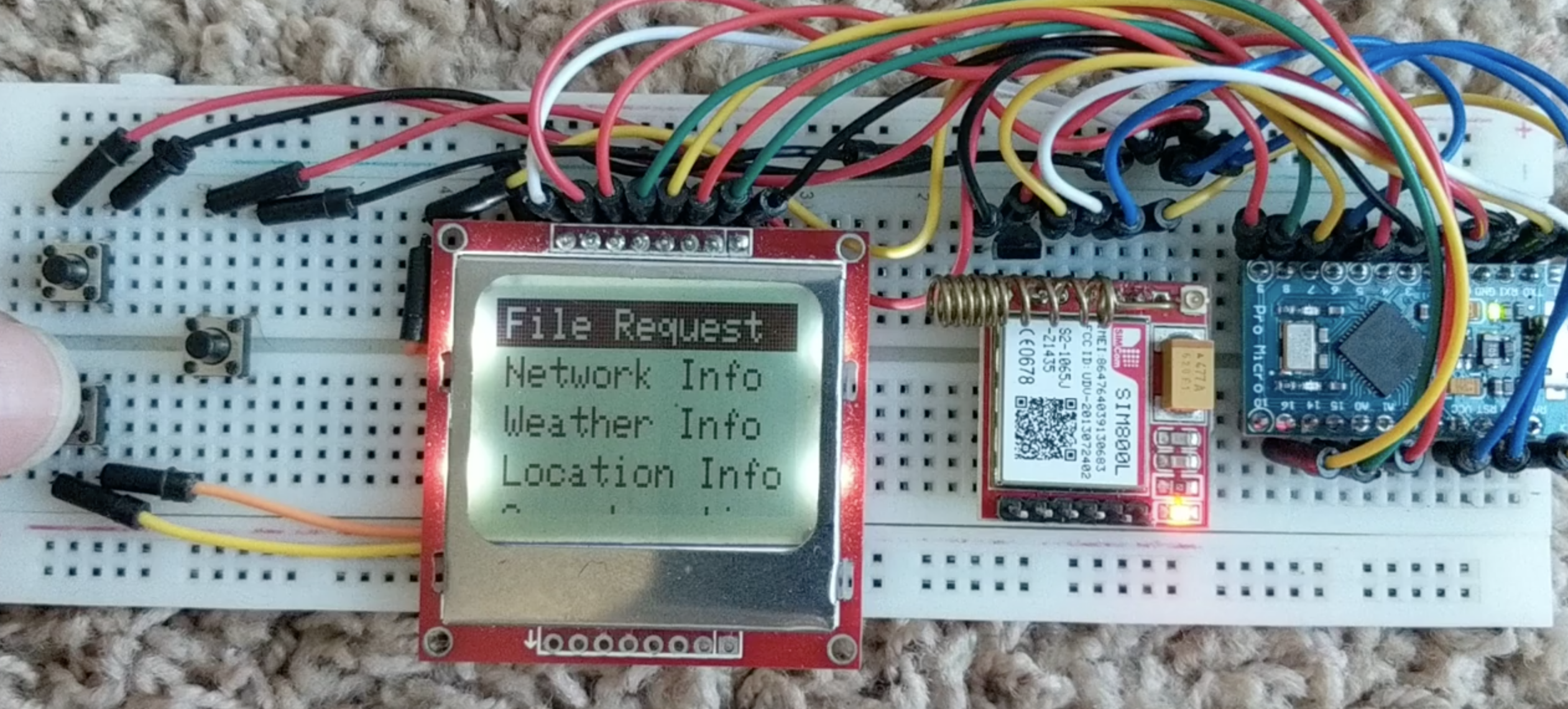
With all the libraries required, installed, copy the code above or from the download section, and upload to the Arduino board. Ensure you select the right board (Arduino Pro Micro) when uploading and ensure all the connections have been double-checked to prevent any error or damage to your components. With the code upload successful, you should see the screen come up as shown in the image below.
Demo
Navigate through the screen using the pushbuttons and try some of the functions out like in the video below.
Going Forward
Over the past few tutorials, we have done massive work on how you can build menu into your own Arduino. With today’s project, we pushed the boundaries further by incorporating a GSM module. These, in my opinion, provides the building block you need to build a DIY feature phone for instance or go further on a more serious note to build a GSM Based Alert system or a GSM-based alarm system with interactive menu, or two-way communication system. The possibilities are endless and it all depends on your imagination.
That’s it for today’s tutorial, thanks for reading. You can watch the video version of the tutorial by HA4ever37 on youtube.
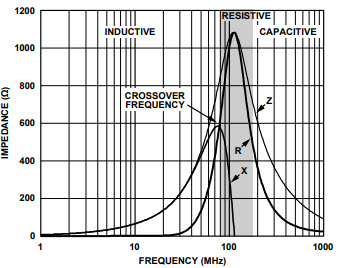
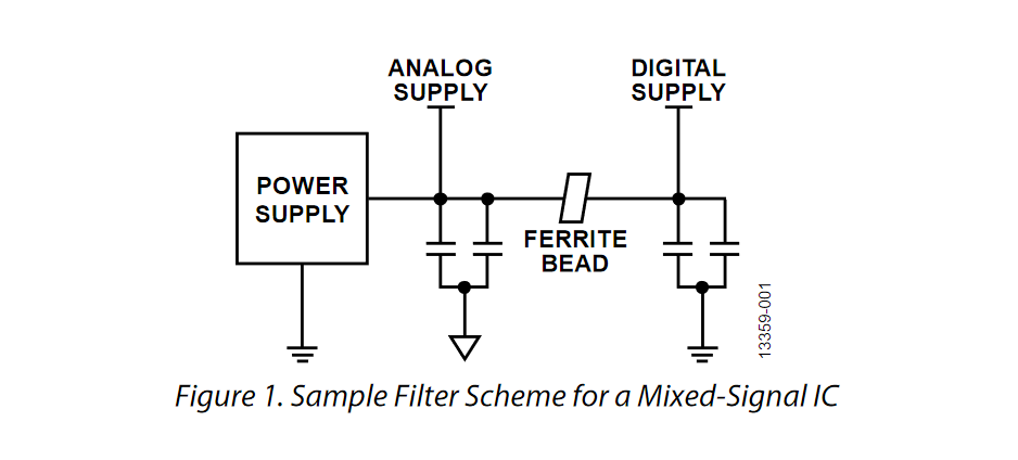
App note from Analog Devices hinting for proper selection of ferrite bead for you applications.
An effective method for filtering high frequency power supply noise and cleanly sharing similar supply rails is the use of ferrite beads. A ferrite bead is a passive device that filters high frequency noise energy over a broad frequency range. It becomes resistive over its intended frequency range and dissipates the noise energy in the form of heat. The ferrite bead is connected in series with the power supply rail and is often combined with capacitors to ground on either side of the bead. This forms a low-pass filter network, further reducing the high frequency power supply noise.
Ferrite bead demystified from Analog Devices – [Link]
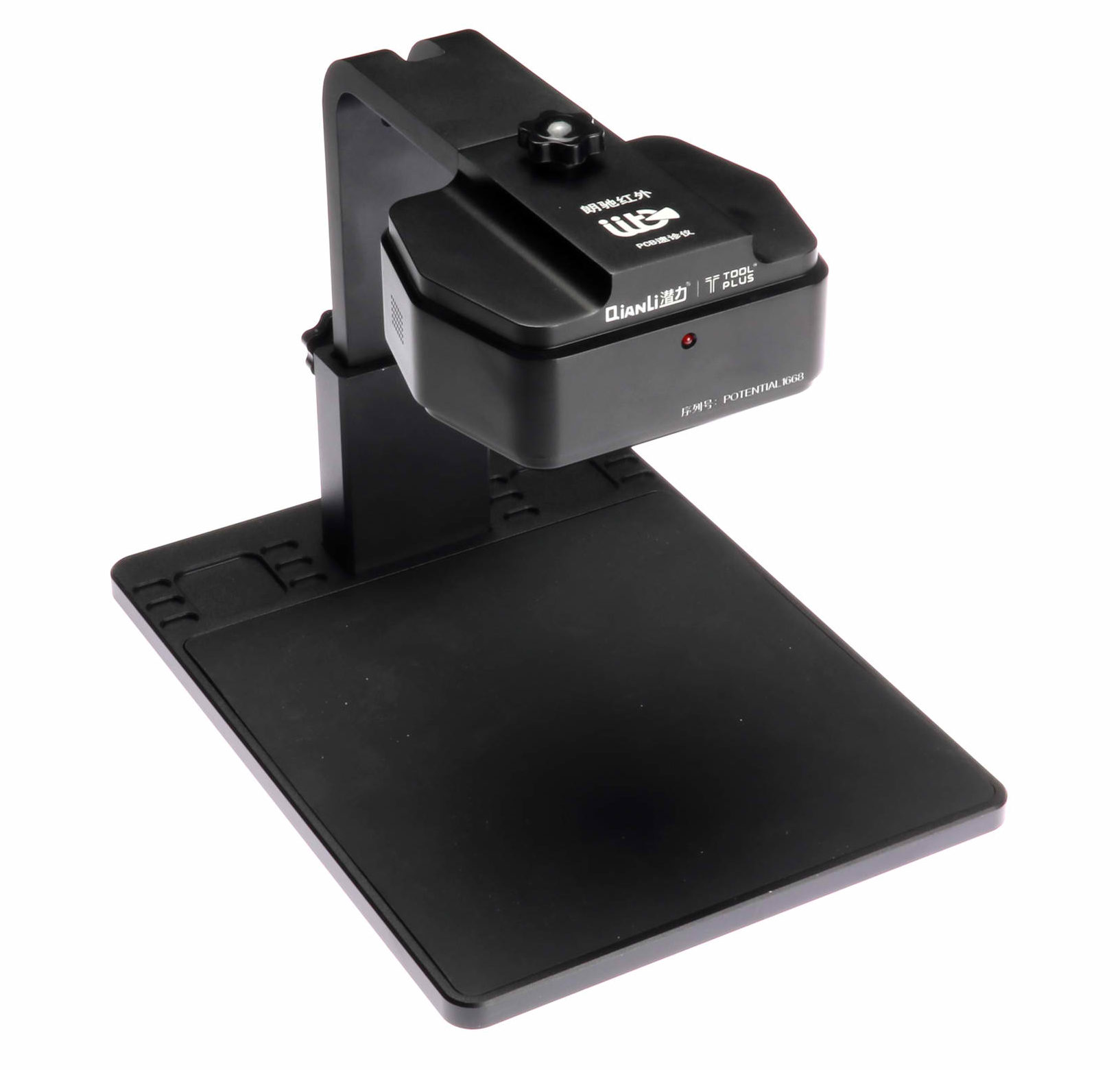
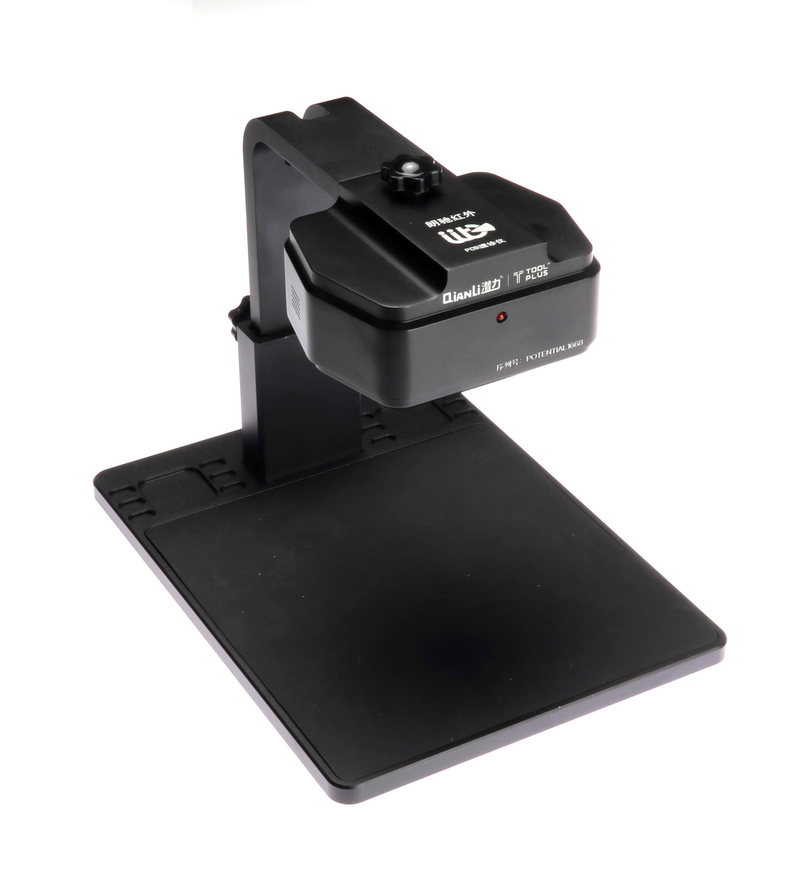
The QianLi’s 160×120 thermal imaging sensor and 1920×1080 visible sensor combine to make a powerful circuit board repair tool, especially helpful in finding overheating or short-circuit issues.
Saelig Co. Inc. has introduced the QianLi LC-IRP01 Thermal Imaging Camera, a diagnostic tool for PCBs which displays heat images to help identify damaged or malfunctioning components or short-circuits. The QianLi LC-IRP01 Thermal Microscope contains two imagers, one for visible wavelengths and one for infrared heat images. These images can be combined on a PC display to quickly identify problem areas. Searching for missing, incorrect or charred components, bad solder joints, and solder bridges becomes much easier with this powerful thermal microscope.
The QianLi Thermal Imaging Camera consists of three parts: the detection head with both an infrared camera and a visible wavelength camera, an adjustable stand, and the powerful computer analysis software. This thermal detection device can display a visible light image, an infrared thermal image, or a visible/infrared superimposed image. This unique combination quickly shows the location of suspect chips or short circuits by switching between both images via the keyboard’s space bar.
Visual inspection with the QianLi’s 1920×1080 sensor is a valuable tool in PCB debug activities, but the addition of 160×120 thermal imaging is especially helpful in finding overheating issues. Rather than using a thermocouple to find the temperature of an individual component, the QianLi displays all of the board temperatures at once. Looking for solder whiskers or bridges between pads or solder joints is especially challenging between the pins of fine-pitch SMD chips without significant magnification, and this device offers 800x digital zooming. If the problem is a short circuit, it will be plainly visible on the PC as an anomalous heat spot when power is briefly applied.
Using a normal/test board comparison analysis, the powerful intelligent PC analysis software supplied can quickly and accurately identify problem chips or short-circuits, which greatly speeds up fault detection, and improves operational efficiency and maintenance accuracy. Finding short-circuits on a PCB can be very difficult by other means. The PC software’s algorithms can detect and highlight thermal anomalies on a wide area – problems such as overheating motherboard chips or short circuits, which are hard to detect by other methods. By comparing normal and abnormal boards, it can help in quickly and accurately identifying circuit board faults. The maximum value component temperature can be also correctly displayed. The software provided can save images or video to preserve maintenance records, video evidence of faults, and provide dated reference comparisons for future maintenance or reports.
The QianLi LC-IRP01 Thermal Imaging Camera is available now from Saelig Company, Inc, starting from $995.
Interested in controlling an object or device without physically touching it? So am I! For today’s tutorial, we will look how to build a DIY based Gesture Controlled Robotic Arm using the Microchip MGC3130 based, Seeed 3D gesture and position tracking shield for Raspberry Pi.
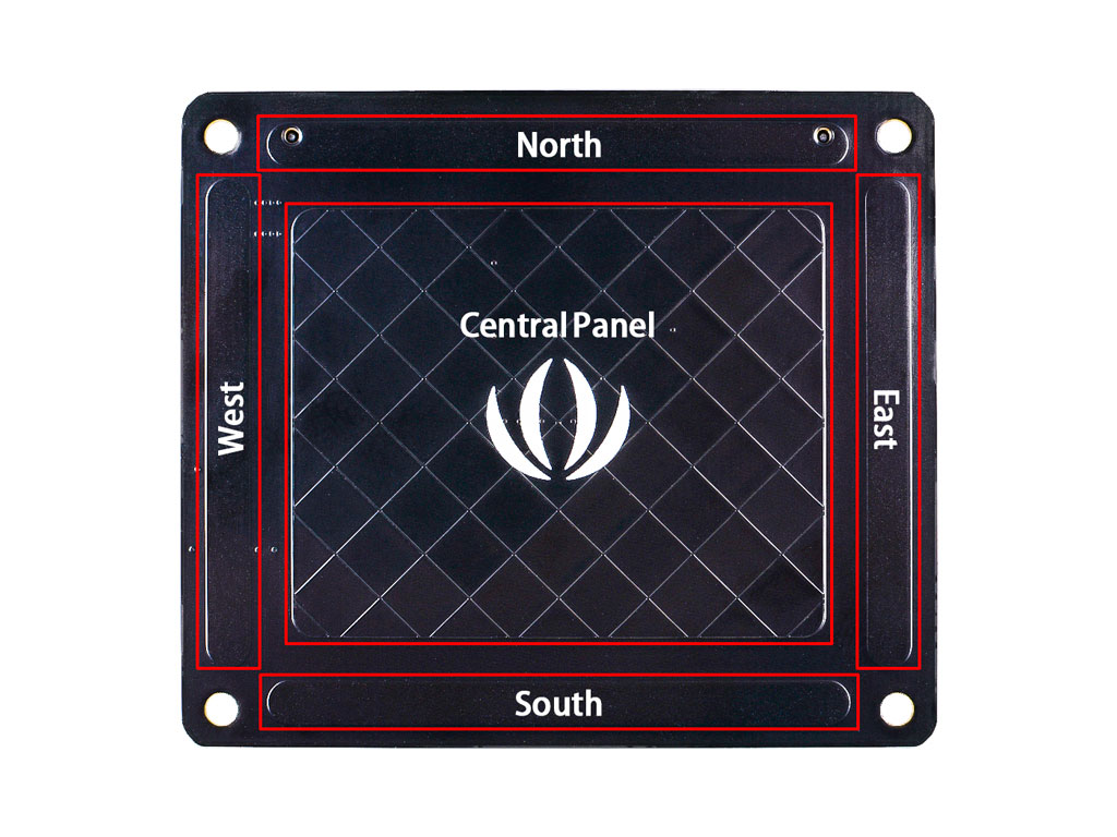
3D tracking has been one of the easiest ways of implementing Natural User Interfaces into devices as it allows users to interact with physical objects without touching them. This is exactly the capability that the Seeed 3D Gesture shield brings to the raspberry pi. This shield is based on the Microchip MGC3130 chip, which enables the Raspberry Pi with 3D gesture recognition and motion tracking function. It can capture x y z position information, can also do proximity sensing and touch sensing, support tap, and double click. As shown in the figure below, the recognition area is divided into two parts: the strip area distributed around and a central panel.
3D Gesture Controlled Robotic Arm using the Seeed MGC3130 and Raspberry Pi – [Link]
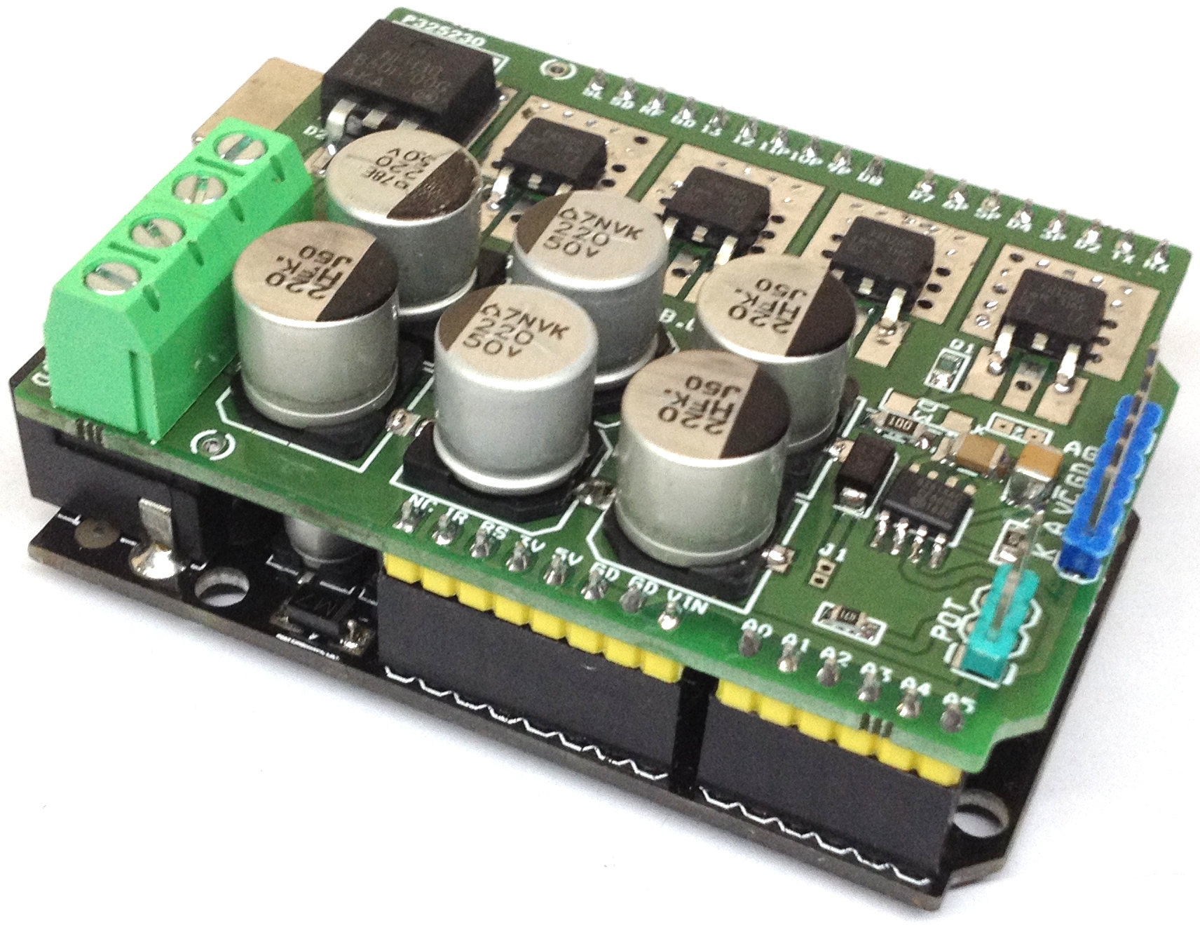
Isolated high power Mosfet DC solid state relay shield allows you to control high current DC load in switching or PWM control mode. The project can be used in wide verity of applications like DC-DC Converters, inverters, DC motor control, solenoid, LED Dimmer, battery chargers and it can control inductive and resistive loads. On board high current fast recovery diode across the load provided for back EMF protection. The board can control load up to 25A with input supply up to 48V DC. High voltage DC input supply up to 90V is possible by altering DC bus capacitor voltage. Input PWM frequency up to 100 KHz duty cycle 0-100%. Mosfet power driver is isolated from Gate driver input. Gate driver circuitry requires 15V DC. Load supply 15V to 48V DC. Jumper J1 helps to use common supply for Arduino and gate driver. Screw terminal CN3 helps to connect load supply and load. Anode of gate driver connected to D3-PWM pin of Arduino to feed PWM signal or ON/OFF. P1 Potentiometer connected to Analog pin A0 of Arduino to adjust the PWM. Higher current Mosfets can be used to get more output current. Gate input requires TTL level signal.
Isolated High Power DC Solid-State Relay Shield for Arduino – [Link]
I think we all have been there – “How do I power my Pi?”
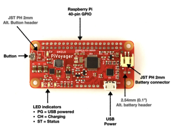
One of the concerns that come with working with the Raspberry Pi is a power supply. As you begin to use your Raspberry Pi to create complex projects, the burden of supplying a portable power supply to it becomes more. With super powerful processing capabilities which makes it useful for everyday computing and sometimes as the brain behind most systems and standalone projects, The Pi is a very useful Single Board Computer (SBC) that is very good at what it does but isn’t exactly the easiest thing to supply power to. To help users get over this power constraint, the Omzlo’s PiVoyager was created.
PIVoyager
The Omzlo’s PiVoyager was designed to make powering the pi less complicated and less stringent. The UPS product from the NoCAN IoT Platform team, when compared with other UPS HaT like the PiJuice Zero, is much lower in price and serves at a relatively higher capacity.
While it is fully compatible with Pi Zero form factor because of the way it is shaped (Pi Zero HaT), it can conveniently work well with any Raspberry Pi with the general 40-pin header in the Pi 2, 3, B+ and 4.
The UPS Hat is a special one with a real-time calendar clock that stores the current date and time while using it with your Raspberry. It comes with a programmable watchdog that powers the Raspberry Pi when it becomes inactive and a wake-up/alarm feature that powers up the Pi at a specific date and time, which could be a very useful feature for certain projects.
Some of the other features of the PiVoyager includes;
Monitoring the battery voltage and the power status of your Pi
it powers up the Pi after a certain delay and forces it to shut down entirely after a certain specified delay.
A built-in bootloader to update the firmware through 12C and a battery connector with an alternative 2-pin header of 2.54mm for connection.
Indicators to show operational status
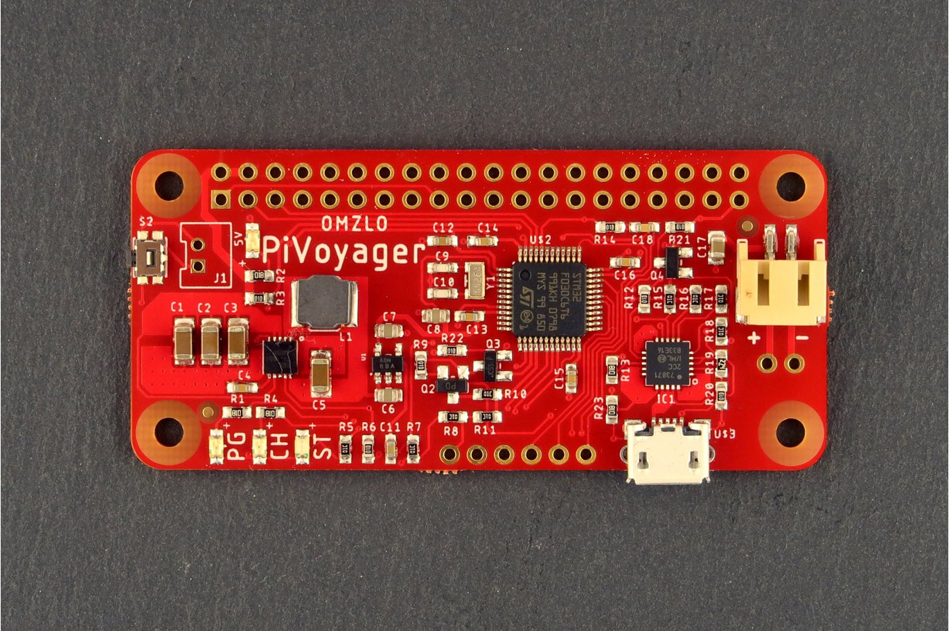
PiVoyager Layout
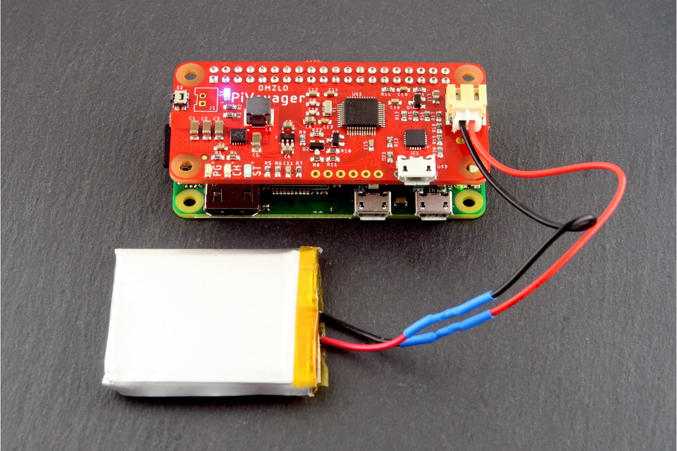
The PiVoyager is specially designed to work with standard LiPo or Li-Ion batteries as an uninterruptible power supply for the Raspberry Pi. It can power the Pi and at the same time charge a Li-Ion/LiPo battery. When the Hat is plugged to the USB power course, it powers and charges the Pi. It supports a default charge current of 1000mA and it is targeted at batteries with a nominal voltage of 3.7V and a charging voltage of 4.2V.
The PiVoyager will not only help to power your Pi but will also supply the right amount of power to it. It can automatically provide a maximum current of 2.1A at 5V to your Raspberry Pi even after the USB is removed without having to switch off the Pi. However, the PiVoyager doesn’t have an in-built battery protection circuitry, so, you have to be careful because things could go wrong if you mistakenly misconnect the terminals of your battery to the HaT.
The Pivoyager is available at Tindle for purchase for $34.66 (with VAT) and $27.95 (without VAT and shipping).
The PiVoyager is open-source and its schematics and firmware can be found on GitHub.
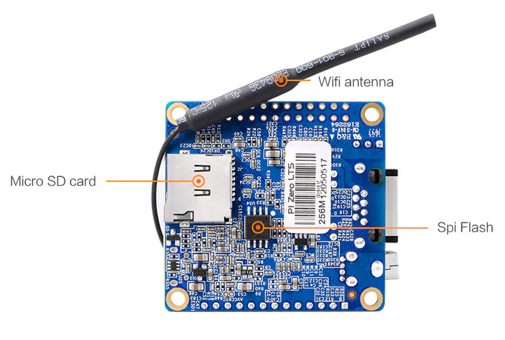
Orange Pi has launched their new Pi Zero LTS development board equipped with an Allwinner H2+ SoC. The Orange Pi Zero LTS, it is an update to Orange Pi Zero Allwinner H2+ board, and has the same specifications, but with changes to the hardware that Shenzhen Xunlong Software claims lower power consumption and reduced heat. Zero LTS features the same SoC and hardware as the Orange Pi Zero. The Orange Pi Zero’s less energy and less heat production features are good marketing strategies, especially for those who do not own the original Zero or have knowledge of it.
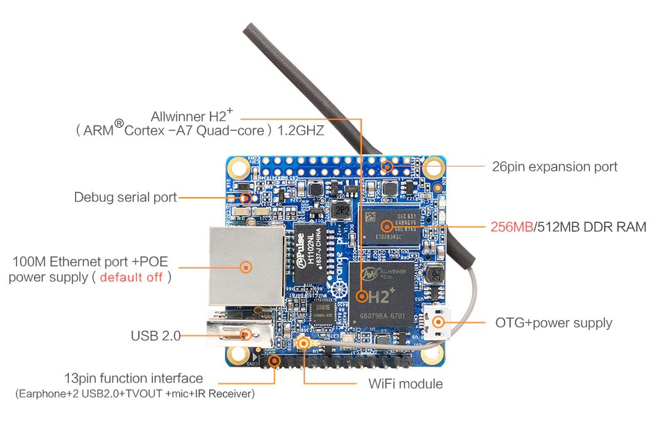
The SBC enables Armbian’s Debian and Ubuntu images and is most suitable for headless applications that require network connectivity via Ethernet and/or WiFi such as smart speakers. On the hardware features, the Orange Pi Zero LTS is based on an Allwinner H2+ SoC with quad-core Cortex-A7 processor with 256Mb or 512Mb of DDR3–1866 SDRAM, SPI Flash, and Mali-400MP2 GPU. It includes a micro SD card slot, 10/100 Ethernet port with PoE (default off), Allwinner XR819 module with 802.11b/g/n Wi-Fi with u.FL antenna connector and external antenna, USB 2.0 port, and micro USB port. For expansion features, there is an unpopulated 26-pin GPIO header compatible with the Raspberry Pi and a 13-pin header with headphone, two USB 2.0, microphone and IR receiver. There is no video output, except for the TV out on the header for composite video.
The SPI flash can be used to store U-boot, so network boot is possible without the need for a microSD card. Available also are a three-pin header for console/debugging applications, a pair of LEDs, and power supplied via micro USB port or PoE. As for software, Orange Pi offers Debian, Ubuntu, Raspbian, Android4.2/7.0, and OpenWRT images, although they are under the Orange Pi Zero category on the company’s download page, but if you want to avoid the stress of searching for images, go for one of the Linux images on Armbian website instead.
It worthy to note that at this point Orange Pi does not provide any official explanation on exactly how they improved the power consumption and heat reduction of the Pi Zero, it is most likely they lowered the SoCs voltage, which would also reduce its performance.
Specifications for the Orange Pi Zero LTS includes :
Connectivity – 10/100M Ethernet, 802.11 b/g/n WiFi via Allwinner XR819 module with u.FL antenna connector and external antenna, USB – 1x USB 2.0 host port, 1x micro USB OTG port, Expansion headers, Unpopulated 26-pin GPIO header mostly compatible with Raspberry Pi (1) header, 13-pin header with headphone, 2x USB 2.0, TV-out, microphone and IR receiver signals
Debugging – 3-pin header for serial console
Misc – 2x LEDs
Power Supply – 5V via micro USB port or optional PoE
Dimensions – 48 x 46 mm
Weight – 26 grams
You can buy the Orange Pi Zero LTS on AliExpress for the same price as the original model, which goes for $8.49 for the 256MB RAM version, and $10.49 for the 512MB model, excluding shipping costs.