Redefining Radio Telescope Digital Backend Receivers with RFSoC Technology

There is a new era of multi-frequency astronomy, in which equipment for observing different types of radio waves is used together to reveal more than they could do individually. In much the same way that you tune the radio to a particular station, radio astronomers can tune their telescopes to pick up radio waves millions of light years from Earth. Using sophisticated computer programming, they can unravel signals to study the birth and death of stars, the formation of galaxies, and the various kinds of matter in the Universe.

A radio telescope is a specialized astronomical instrument designed to detect and study radio-frequency radiation between wavelengths of about 10 meters (30 megahertz [MHz]) and 1 mm (300 gigahertz [GHz]) emitted by extraterrestrial sources, such as pulsars, stars, galaxies, and quasars.  Detecting faint radio emissions relies on the antenna’s size and efficiency, along with the receiver’s sensitivity for signal amplification and detection. A digital backend receiver is a vital component in a radio telescope system, responsible for digitization, signal processing, and high-speed data transmission.

Radio telescopes typically have three basic components,

  1. One or more antennas pointed to the sky to collect the radio waves
  2. A receiver and an amplifier to boost the very weak radio signal to a measurable level
  3. A recorder to keep a record of the signal

RFSoC: A Building Block for Radio Telescopes

The RFSoC unifies RF data converters, programmable logic, and microcontrollers, providing essential functions for radio astronomy backends like real-time signal processing, digitization, high-speed interfacing, and software control. This highly integrated and power-efficient RFSoC streamlines astronomical backend system design, simplifying the architecture and reducing hardware development costs.

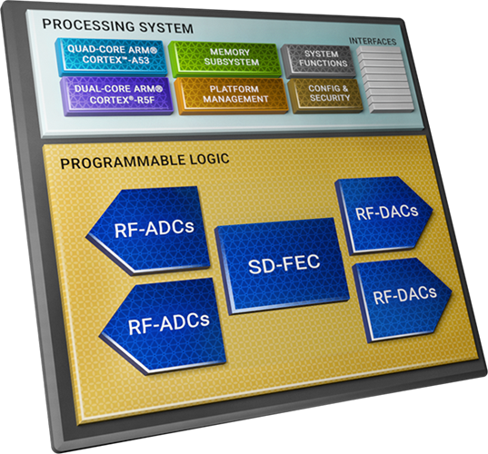
The Zynq UltraScale+ RFSoC offers high-performance analog-to-digital conversion, real-time signal processing capabilities, and extensive bandwidth coverage, making it an ideal solution for designing radio telescope backend receivers.

  1. High-Speed Analog-to-Digital Conversion (ADC)
    The RFSoC integrates high-speed ADCs capable of digitizing radio signals with high precision and speed. Pulsar signals are often faint and require sensitive receivers with fast sampling rates.
  2. Real-Time Signal Processing
    The integration of FPGA and ARM processors within the RFSoC enables real-time processing of radio signals. This feature is invaluable in radio astronomy, allowing for the rapid analysis of celestial data and the detection of transient events, such as fast radio bursts and pulsar emissions.
  3. Versatility and Adaptability
    FPGAs are known for their reconfigurability. Radio astronomy often involves implementing various algorithms to detect weak signals, perform pulsar searching, and conduct interference mitigation.
  4. Energy Efficiency
    Radio telescopes are often located in remote or off-grid areas to minimize interference from human-generated radio signals. The energy-efficient design of the RFSoC is crucial for maintaining these observatories and ensuring their uninterrupted operation.
  5. High-Speed Data Transfer
    The inclusion of high-speed serial transceivers facilitates the efficient transfer of large datasets from radio telescopes to data processing facilities. This is essential for interferometry applications and the creation of high-resolution images using data from multiple telescopes.

RFSoC-based Backend Design

To ensure high-fidelity observational data and meet diverse scientific objectives, a multi-function digital backend can be designed with cutting-edge technologies like ZU49DR Zynq UltraScale+ RFSoC development boards. This advanced system directly samples RF signals at the receiver’s front end and offers flexible processing modes. This approach effectively mitigates signal gain and phase fluctuations caused by environmental factors during transmission.

The figure below provides an overview of the radio telescope backend system, which is built on a heterogeneous architecture incorporating RFSoC, CPU, and GPU components. It includes a Signal acquisition and pre-processing block, a multi-function post-processing block, and a recorder/storage.

Block Diagram of a Digital Backend Receiver

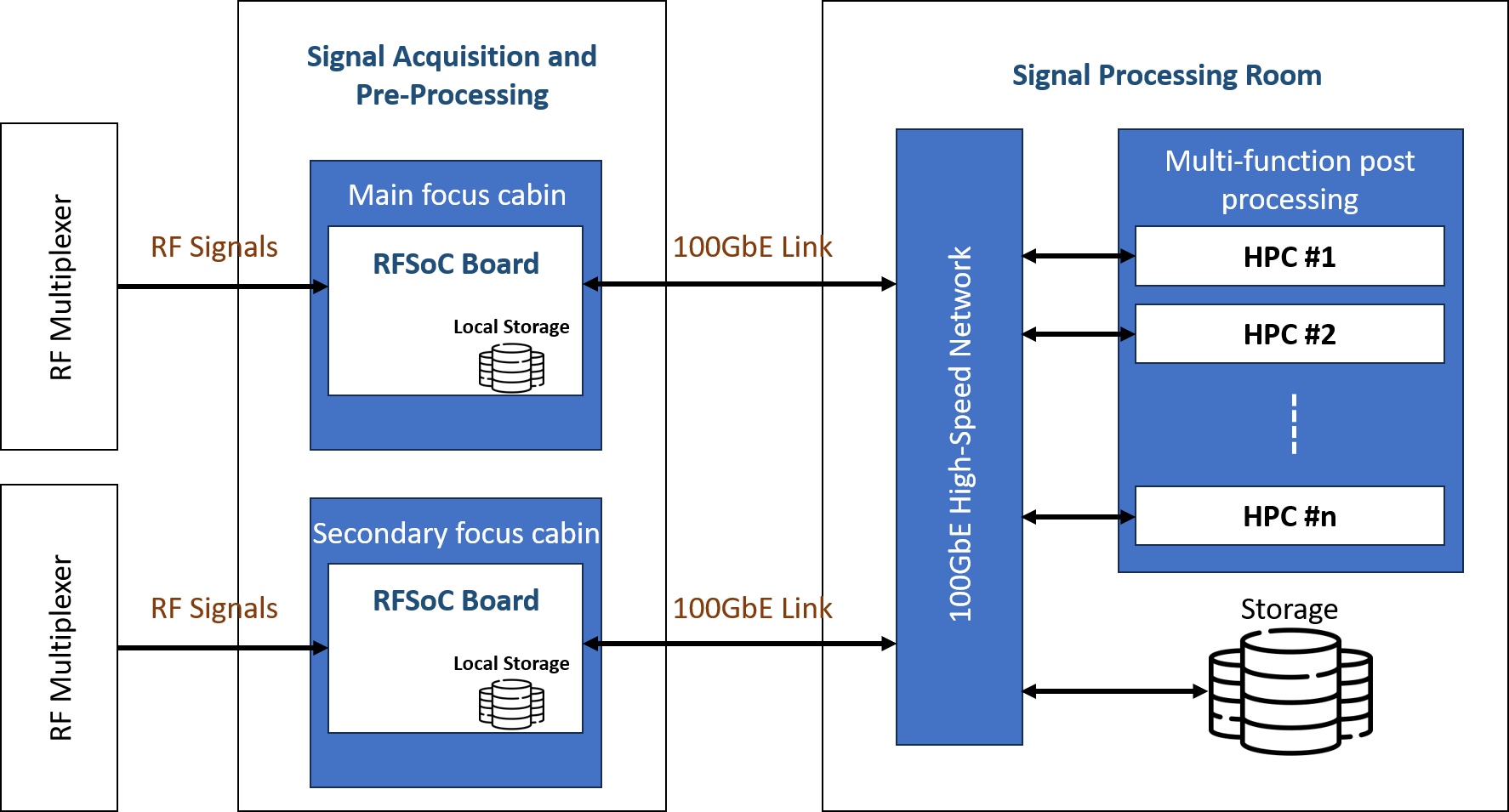
The signal acquisition and preprocessing unit utilize high-performance, low-power RFSoC technology with integrated high-speed 2.5 GSPS ADCs at 12-bit precision. RF multiplexers switch signals from various receivers, covering the entire passband with a maximum simultaneous bandwidth of 14 GHz. It also possesses local storage capabilities for retaining received signals, which can be transmitted to a post-processing unit when necessary for further processing.

The multifunctional post-processing unit accepts high-speed digital signals via a 100 GbE data exchange network. It enables the selection and loading of signal processing modes, including pulsar, spectral line, continuum, and baseband modes. The system offers Radio Frequency interference (RFI) mitigation options tailored to the observed electromagnetic environment. This unit comprises multiple high-performance computer (HPC) nodes that dynamically adjust CPU and GPU computing cores to match signal processing bandwidth and complexity, ensuring flexibility and scalability. Processed high-speed data is buffered into the storage, capable of handling data at a maximum rate of 4 GB/s.

The RF data converters are laid out in tiles, each containing up to four RF-DACs or RF-ADCs. There are multiple tiles available in RFSoC, such that each tile also includes a block, clock handling logic, and distribution routing. This hierarchy of tiles and blocks simplifies the data converter design and implementation.

Designing Radio Telescope Digital Backends using iW-RainboW-G42M System on Module: Powered by AMD Zynq UltraScale+ RFSoC

iWave has designed a powerful System on Module, powered by the ZU49DR RFSoC, that can speed up the design of radio telescopes and utilize the feature-rich RFSoC. The RFSoC SoM features the industry’s highest RF channel count with 16 Channel RF-DACs @ 10GSPS and 16 Channel RF-ADCs @ 2.5GSPS.

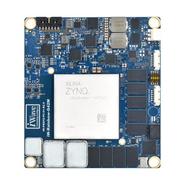
iW-RainboW-G42M System on Module features the ZU49DR and is compatible with the ZU39 and ZU29. The SoM offers a multi-element processing system, including an FPGA, Arm Cortex-A53 processor, and a real-time dual-core Arm Cortex-R5, and high-speed ADC & DAC channels, which makes it able to acquire, process, and act on RF signals. The RFSoC SoM offers onboard 8GB 64bit DDR4 RAM with an error correction code for the processing system and 8GB 64bit DDR4 RAM for programmable logic.

The integrated ultra-low noise programmable RF PLL simplifies the utilization of the SoM in the end product, eliminating concerns about complex clocking architecture. This integration also empowers the system with the highest signal processing bandwidth throughout the comprehensive RF signal chain. Furthermore, it boasts support for SyncE and PTP network synchronization, ensuring a high degree of synchronization.

The module leverages the AMD Zynq UltraScale+ RFSoC Gen3 device, making it ideal to be deployed into RF systems that demand small footprint, low power, and real-time processing. Furthermore, the SoM brings in a drop-in solution for customers who want to simplify the design architecture, expedite the implementation process of astronomical digital backends for radio telescopes, and reduce device power consumption and hardware development costs.

iWave has also engineered an innovative RFSoC PCIe ADC DAC data acquisition card, driven by the G42M Zynq UltraScale+ RFSoC SoM. The 3/4 Length PCIe Gen3 x8 Host Interface on the board connects the RFSoC PCIe Card to the computer/server.

This card incorporates state-of-the-art RF and signal integrity design techniques to ensure high-speed connectivity. Its adaptability enables users to seamlessly integrate this technology into their specific applications, offering a versatile solution for field deployment.

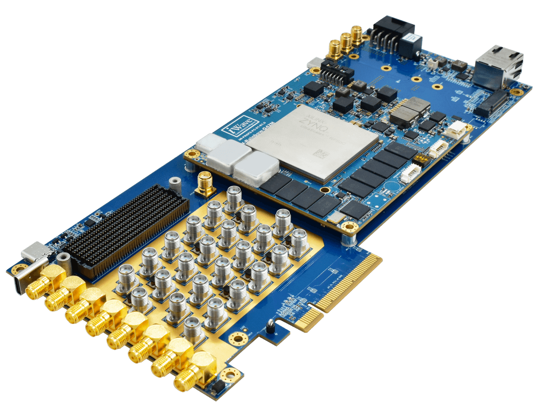
Complementing the RFSoC’s on-chip resources, the iWave RFSoC ADC DAC PCIe Card adds,

  • 16 ADC Channels
    • 4 x Right Angle SMA connectors on the Front Panel with Balun (BW-800MHz-1GHz)
    • 4 x Straight SMA connectors with Balun (BW-800MHz-1GHz)
    • 4 x Straight SMA connectors with Balun (BW-700MHz-1.6GHz)
    • 4 x Straight SMA connectors with Balun (BW-10MHz-3GHz)
  • 16 DAC Channels
    • 4 x Right Angle SMA connectors on the Front Panel with Balun (BW-800MHz-1GHz)
    • 4 x Straight SMA connectors with Balun (BW-800MHz-1GHz)
    • 4 x Straight SMA connectors with Balun (BW-700MHz-1.6GHz)
    • 4 x Straight SMA connectors with Balun (BW-10MHz-3GHz)
  • NVMe PCIe Gen2 x2/x4 M.2 Connector
  • FMC+ HSPC Connector

The System on Module and the PCIe Card are go-to-market and production-ready complete with documentation, software drivers, and a board support package. iWave maintains a product longevity program that ensures that modules are available for long periods of time (10+ years).

For more information, please contact mktg@iwavesystems.com

ASRock Industrial’s 4X4 BOX 8040 Series Mini PC with AMD Ryzen™ 8040 Series Processors Brings AI PC into Your Life

ASRock Industrial releases state-of-the-art 4X4 BOX 8040 Series Mini PCs and 4X4 8040 Motherboard Series, powered by AMD Ryzen™ 8040 Series APUs, crafted to elevate trusted performance and AI PC capabilities. Featuring up to 8 “Zen 4” cores/ 16 threads and AMD Radeon™ 700M graphics, the Series integrates AMD Ryzen™ AI with 16 NPU TOPS, delivering up to 1.6x surge in AI processing performance over its predecessor. With support of dual-channel DDR5 5600MHz memory up to 96GB, the 4X4 BOX 8040 Series comes with enriched I/O connectivity in a compact fanned box. It enables 4K quad-display outputs, five USB ports, including two USB4, accommodates dual storages, and offers dual LAN up to 2.5G, along with Wi-Fi 6E support. The new Series, marked by a significant speed boost with lower power consumption, paves the way for accelerated generative AI workloads, tailoring heightened experience in content creation, gaming, entertainment, office productivity, commerce, and many other AIoT applications through the quintessential AI PC for you.

The 4X4 BOX 8040 Series Brings Upgrades with AMD Ryzen™ 8040 Series APUs

ASRock Industrial’s 4X4 BOX 8040 Series offers versatile selections: 4X4 BOX-8840U, 4X4 BOX-8640U, powered by AMD Ryzen™ 8040 Series (Ryzen™ 7 8840U/ Ryzen™ 5 8640U). With integration of CPU, GPU, and NPU, the AMD Ryzen™ AI upgrades to 16 NPU TOPS and 39 total TOPS (NPU+CPU+GPU), reaching up to 1.6x surge in AI processing performance and a notable 40% speed increase in running AI LLM models than prior gen AMD APUs. Featuring 4nm “Zen 4” architecture with up to 8 cores/ 16 threads, along with AMD Radeon 700M RDNA™ 3 graphics, and dual-channel DDR5 5600MHz SO-DIMM memory up to 96GB. The 4X4 BOX 8040 Series marks a leap forward in AI processing, allowing users to reimagine dynamic applications on their AI PC, such as enhancing productivity, delivering AI-inspired visuals/content, running AI models right on PCs for various AIoT use cases.

The 4X4 BOX 8040 Series Features Excellence

The 4X4 BOX 8040 Series’ enriched I/O connectivity in a compact size of 117.5 x 110 x 49 mm fanned barebone. With integrated AMD Radeon™ 700M Graphics, the Series supports 4K quad-display outputs through two HDMI 1.4b and two DisplayPort 1.4a (with two from Type-C), delivering marvelous visual experience. For dual-storage capabilities, the Series includes one M.2 (Key M, 2242/2280) and one M.2 (Key M, 2242) with PCIe Gen 4×4 for SSD ensuring maximum scalability. In addition, the 4X4 BOX 8040 Series is equipped with dual LAN ports- one 2.5G and one 1G port along with Wi-Fi 6E and Bluetooth 5.2 support to deliver high-speed communication. It also features two USB4, one USB 3.2 Gen2 (Type-A), and two USB 2.0 ports, accompanied by AMD firmware TPM for trusted security. With the 4X4 BOX 8040 Series, you can now seamlessly integrate limitless AI applications into your AI PC.

What’s more: 4X4 8040 Motherboard Series

ASRock Industrial also introduces 4X4 8040 Motherboard Series powered by AMD Ryzen™ 8040 Series APUs (Ryzen™ 7 8840U/ Ryzen™ 5 8640U) in a compact 4X4 form factor. Key features comprise support for two SO-DIMM DDR5 5600 MHz up to 96GB memory. The Series is equipped with one 2.5G LAN and one 1G LAN for reliable communication, plus one M.2 Key E (2230) with PCIe Gen4x1 for wireless. For stunning visuals, the Series supports 4K quad-display through two HDMI 1.4b and two DP 1.4a (with two from Type-C) with AMD Radeon™ 700M Graphics. Dual storage options are supported with one M.2 Key M (2242/2280) and one M.2 Key M (2242) with PCIe Gen4x4 for SSD. Optimized for overall capacity, the motherboard series excels in I/O connectivity and expansions with two USB4, one USB 3.2 Gen2, two USB 2.0 ports, and one COM (TTL-3V) connector. Moreover, a 12~24V DC-in design with flexible power input, 0~70°C wide range operating temperature, with the AMD firmware TPM for software-based security. The 4X4 8040 Motherboard Series introduces speed and capability enhancements for home, business, and embedded use cases.

Bring AI PC into your life with the arrival of the 4X4 BOX 8040 Series and 4X4 8040 Motherboard Series, powered by AMD Ryzen™ 8040 Series APUs. The new Series unlocks new upgrades in computing speed, graphics performance, and AI processing power, providing an ideal platform for generative AI applications and workloads. With integrated enhancements, the 4X4 BOX 8040 Series and 4X4 8040 Motherboard Series stand as the optimal partner to bring AI applications to life.

For more detailed information, please visit our Website, or contact us at Product Inquiry.

Huge Savings on InfiRay Xinfrared Thermal Cameras!

InfiRay Xinfrared P2 Pro and T2S Plus Thermal Cameras

As every engineer understands, executing a task effectively depends on having the right tool at the right time. But quality tools and equipment can be costly, which is why this Black Friday presents an exceptional opportunity for substantial savings on two of the most innovative camera accessories in the market: the InfiRay Xinfrared P2 Pro and T2S Plus Thermal Cameras. The current offer is as follows:

  • Original Price: $339 for the T2s Plus, $299 for the P2pro.
  • Black Friday Price: Just $271 for the T2s Plus, and $208 for the P2pro.
  • Your Savings: An impressive $68 on the T2s Plus, and a whopping $91 on the P2pro!

This Black Friday, InfiRay is offering a substantial 30% off on the P2Pro Cameras, and a similar fantastic deal is now available for the InfiRay Xinfrared T2S+ Cameras. Known for their compact size and high functionality, the T2S+ and P2Pro are invaluable tools for a wide range of inspection tasks.

While reviewing the InfiRay Xinfrared T2S+ and InfiRay Xinfrared P2 Pro Thermal Cameras we found their capabilities up to the mark. The camera’s ability to measure temperature and its night vision capabilities make it a versatile tool.

This camera has a tiny footprint, and it measures (26 x 26 x 24.2mm). It comes in two different variants, compatible with both Android (USB-C) and iOS (Lightning port) devices.

With a 25Hz refresh rate, the T2S+ offers smooth and clear images and videos. The “picture in picture” mode, combines regular and thermal imagery. It also features multiple palette options, including an X-ray-like view, which are features that will come in handy in low light conditions.

This Black Friday, don’t miss the chance to add the InfiRay Xinfrared T2S+ Thermal Camera to your toolkit at an unbeatable price. Whether you are a professional or a DIY enthusiast, or someone who appreciates the practical applications of thermal imaging, the T2S+ is an excellent investment, now more affordable than ever.

Grab this deal while it lasts: Available on both the Shopify and Amazon stores of InfiRay with Promo Code: electronics5

New Grid-EYE – 90° from Panasonic increases field of vision for Machine Learning based IR sensing

Panasonic Industry has launched a new member of its popular Grid-EYE sensor family featuring a 90° lens delivering a wider field of view (FoV) and reducing the number of sensors required to cover a given area to enable people counting and tracking applications. Privacy conscious designers have appreciated the 64 pixel resolution of the Grid- EYE family, and the Grid- EYE 90° will enhance systems designed to track and count the movement of people tracking as well as other applications.

Comments Osamu Mitsumura, Product Manager at Panasonic Industry Europe: “Knowing where people are is the key to design a smart space. Today, industries want to understand and optimize how their buildings are being used, especially the businesses in retail, hospitality and healthcare. Similarly, the lighting industry is increasingly moving towards providing personalized ambient spaces. The pandemic has also highlighted the importance of management of highly frequented or confined spaces – like offices or public washroom facilities. The holy grail of people-tracking/counting solutions has always been Scalability and cost-effectiveness. Grid-EYE 90° delivers both.”

A new sensor with 90° field of view for privacy conscious people tracking

Previously, Grid-EYE has been used in a variety of applications where absolute temperature values are used for detecting hot spots in a smart kitchen or hotter areas of a room for smart air conditioning.

At the same time, Grid-EYE is also highly suitable for people tracking/counting applications. Innovative product designers have used Grid-EYE 60° as a cost-effective alternative to camera or wireless solutions.

The new variant of Grid-EYE builds on Panasonic’s deep expertise of innovative sensing technologies. The new 90° wide-angle lens allows Grid-EYE to have a wider field of view (FoV), improving on previous sensors which offer a 36° and 60° FoV. With the launch of Grid-EYE 90°, system designers can capture the IR signature of a larger area, so fewer sensors are required to cover a given area. This makes it an ideal choice for enhancing the efficiency of people tracking/counting devices.

Low-Res Infrared and Machine Learning: A new approach to counting and tracking

Successful data acquisition using Grid-EYE is only the first step in successfully counting people.  Different techniques can be employed to exploit the sensor data. The use of standard signal processing algorithms works well, but can run into difficulties with infrared sensors. Unlike visual spectrum devices where the quality of data is unambiguous, infrared signals can be tricky to handle when employed in devices – especially the ones with low resolution which can pick up noise very easily, such as Grid-EYE. Everyday occurrences like a hot coffee cup, an open window or an overheating computer, which are not even a subject of discussion in the visual spectrum, are daunting challenges in infra-red. This makes the algorithm development much more complex.

One way to overcome this problem is to use machine learning (ML). ML is a subset of Artificial Intelligence (AI) techniques, that emphasizes on the use of self-learning neural networks to derive inferences from the input data. The neural network can be trained using a known annotated dataset to design a ML model, which can be then deployed in field. This allows offloading complex tasks to neural networks, which previously required customized algorithm and expensive hardware.

Collaboration with CN Group on Dataset acquisition

An ML model with good performance can only be built by training on a good quality dataset. Contrary to more common applications like computer vision where there are rich datasets already available, sensors like Grid-EYE do not often have any datasets to begin with. Recognizing the need to bridge this gap, Panasonic has started a collaboration with CN Group, a software company which is part of the Ciklum company. CN Group has expertise in a wide array of topics including mechanical design, embedded electronics hardware and software, machine learning and IoT. Using a hardware setup which includes Grid-EYE sensor and a camera, CN Group is working to build datasets containing visual and thermal information from an observed scene. Furthermore, using computer vision techniques, the dataset is automatically annotated when humans are detected in the field of view of the camera. CN Group’s contribution in creating quick annotated datasets opens a wide array of possibilities in creating customized thermal datasets for any given location – meeting rooms, staircases, etc. Panasonic and CN group believe that that this collaboration will enable more customized/personalized ML systems for people-tracking/counting using Grid-EYE.

Learn more on the sensor on Panasonic Industry’s website: IR Thermophile array sensor – Grid-EYE | Panasonic Industry Europe GmbH

ENS161 Air Quality Sensor

ScioSense’s range of digital multi-gas sensors is designed for indoor air quality monitoring

ScioSense’s ENS161 is the latest addition to the ENS16x family, a range of digital multi-gas sensors specifically designed for indoor air quality monitoring. Both ENS160 and ENS161 combine the detection of a wide range of gases, including volatile organic compounds (VOCs) and oxidizing gases, with intelligent on-chip algorithms.

The sensor calculates a series of fully processed outputs such as CO2 equivalents (eCO2), total volatile organic compounds (TVOC) equivalents (eTVOC), and a 5-step air quality index (AQI) according to the German Environment Agency, Umweltbundesamt (UBA) (AQI-U), while the ENS161 additionally provides a 500-step relative AQI according to ScioSense (AQI-S) output.

While all this is done on-chip with no required libraries or additional overhead for external controllers or processors, the ENS161 introduces low-power operating modes. By lowering the sample rates of the sensor, low-power and ultra-low-power modes can be offered, reducing average current consumption to 700 µA or 150 µA, respectively. In addition to traditional smart home and building applications, this opens up wearables, battery-powered devices, smart things, and IoT applications to integrate air quality sensing in a space-saving 3 mm x 3 mm LGA package.

Features

  • Multiple, fully processed output signals including eTVOC, eCO2, and AQI outputs AQI-U and AQI-S
  • Low power modes down to 150 μA current consumption
  • On-chip measurement and heater drive control with integrated sensor fusion and automatic baseline algorithms, no need for external libraries
  • TrueVOC® air quality sensor with excellent stability
  • Supply voltage VDD: 1.71 V to 1.98 V
  • Wide operating ranges:
    • Temperature (T): -40°C to +85°C
    • Relative humidity (RH): 5% to 95%
  • Communication through I²C or SPI interface
  • Compact size: 3.0 mm x 3.0 mm x 0.9 mm LGA package
  • Options to access raw sensor data
  • Evaluation kit and dashboard software available

more information: https://www.sciosense.com/products/environmental-sensors/ens16x-digital-metal-oxide-multi-gas-sensor/

Nexperia Battery Life Booster IC

Battery Life Booster IC – Extend coin cell battery life and optimize peak current for pulse load

The NPS4053 switch limits the output current to a constant current by using a constant-current mode when the output load exceeds the current limit threshold or shorted. An internal voltage comparator disables the load switch when the output voltage is higher than the input to protect devices on the input side of the switch. The FLG pin is an active low output to indicate overcurrent, over temperature and reverse voltage conditions.

Features & benefits

  • Programmable constant battery load current: 2 mA to 16 mA
  • Protection against battery voltage dips (Brown-out)
  • Pulse output current: 150 mA
  • Regulated programmable output voltage: 1.8 V to 3.6 V
  • Low output voltage ripple
  • Ultra-low standby current: < 20 nA
  • Typical conversion efficiency of 90% with adaptive optimization
  • Integrated fuel gauge
  • Integrated balancing circuit
  • One auxiliary regulated output pin
  • Small 16 pin lead-free package (SOT763-1/DHVQFN16; 2.5 mm × 3.5 mm × 0.85 mm)
  • Specified from -40 °C to +85 °C

more information: https://www.nexperia.com/products/analog-logic-ics/power-ics/load-switches/series/NPS4053-Q100.html

nRF7002 Based Arduino Shield: Nordic Adds Wi-Fi 6 to Arduino and RPi

The nRF7002 EK is a Wi-Fi 6 evaluation kit in an Arduino-compatible form factor. It’s designed to integrate with various Nordic development kits like the nRF52840 and supports the nRF Connect SDK and code samples. This kit includes the nRF7002-based Arduino Shield and other peripherals. Additionally, Nordic has released a Linux driver for the nRF70 series, enabling compatibility with Raspberry Pi devices.

The nRF7002 is a compact, energy-efficient Wi-Fi 6 chip by Nordic Semiconductor, designed for IoT devices. It supports dual-band Wi-Fi and Bluetooth LE and can be interfaced with SPI/QSPI bus, which makes it ideal for a lot of microcontrollers. It leverages Target Wake Time to save power. It’s integrated into the nRF Connect SDK for development ease.

This board can be integrated with the nRF Connect SDK, and for simplicity, it also includes sample code for development. The whole device is designed with an Arduino shield in mind but its compatibility with standard Arduino boards isn’t specified by Nordic, particularly regarding the use of Wi-Fi/Bluetooth coexistence features. However, it could be managed by an Arduino via the SPI interface with custom-written software.

Nordic recently introduced a Linux driver for its nRF70 chips, which has been successfully tested with a Raspberry Pi 4 using Ubuntu 22.04 64-bit. This setup involved connecting the nRF7002 Evaluation Kit (EK) through a special interposer board. While this interposer board is not available for purchase, its design files are accessible for anyone to build.

Specifications of nRF7002 Based Arduino Shield:

  • Wireless chip – Nordic Semi nRF7002
  • Dual-band Wi-Fi 6 (802.11ax)
  • Wi-Fistation mode
  • Target Wake Time (TWT)
  • 20 MHz channel bandwidth
  • Antenna – 2.4 and 5 GHz antenna for Wi-Fi
  • SWF port for RF measurement
  • Host interface – SPI or QSPI interfaces
  • Dimensions – Arduino shield form factor

The nRF7002 Evaluation Kit is priced at $19 (Not Including Shipping) and available on Crowd Supply, as well as through distributors like Mouser and Digikey. For more information, you can visit the product page.

ESP32-S3 with 3.4-inch Touchscreen: LILYGO New Display Board

LILYGO's latest T-Display-S3-Long is an ESP32-S3 board featuring a unique 3.4-inch wide touchscreen with a 640×180 resolution, tailored for various applications

LILYGO’s latest T-Display-S3-Long is an ESP32-S3 board featuring a unique 3.4-inch wide touchscreen with a 640×180 resolution, tailored for various applications.

This wireless display board features an ESP32-S3R8 WiSoC with 8MB PSRAM and includes a 16MB SPI flash for storage. It also offers two Qwiic connectors, a 30-pin header for additional attachments, a USB Type-C port for power and programming, and a 2-pin connector for an optional LiPo battery. This makes it versatile for various wireless applications.

In the above parts marking image, you can see the placement of the 3D Wi-Fi Antenna, the Qwicc connectors, and the USB-C connector this becomes important because you will need those measurements if you are trying to make an enclosure for this. you can also verify the placement of other critical components like the power switch, the boot, and the power switch, on the ESP32-S3 with a 3.4-inch Touchscreen. You can also verify the placement of the JST battery connector.

The T-Display-S3-Long from LILYGO offers firmware and samples for PlatformIO/Arduino, including factory test code, TFT and touchscreen samples, and an LVGL demo. It also includes PDF schematics, datasheets, and basic documentation on GitHub. However, due to limited documentation and lack of complete projects, it’s best suited for those experienced in Arduino/PlatformIO programming. Beginners might find it challenging to use.

When you purchase the T-Display-S3-Long board, it comes with a set of accessories that includes one T-Display-S3-long-3.4-V1.0 screen, two STEMMA QT/Qwiic interface lines marked with [P352], one battery cable, and one 1.27mm female pin connector with a 2×15 pin layout.

ESP32-S3 Based T-Display-S3-Long Board Features:

  • MCU: ESP32-S3R8, dual-core, AI acceleration, 512KB RAM, 8MB PSRAM, Wi-Fi & Bluetooth connectivity
  • Storage: 16MB flash
  • Display: 3.4-inch TFT LCD, 640×180, capacitive touchscreen
  • Connectivity: Wi-Fi 4, BLE 5.0, Bluetooth Mesh, 3D antenna
  • USB: Type-C OTG port, SY6970 chip for power, charging, and programming
  • Expansion: 2 Qwiic I2C connectors, 30-pin header
  • Other: Boot/Reset buttons, power switch for battery/USB
  • Power: 5V USB-C, LiPo battery connector, SY8089AAAC regulator
  • Size: 92 x 28 x 16 mm

You can purchase the LILYGO’s T-Display-S3-Long ESP32-S3 board at Aliexpress for $34.98 with shipping, but at the time of writing this article, only 6 pieces are left. more information on the device can be found on LILYGO’s official webpage.

New Software Update Enables Bluetooth for Pico W

In a recent announcement, Raspberry Pi has released 1.5.1 of the C SDK along with the latest MicroPython build. This update enables Bluetooth on the Raspberry Pi Pico W.

Launched last year, the Raspberry Pi Pico W is a small, $6 computer module that can be used for various electronics projects. While releasing the board last year, the board already came with the Infineon CYW43439 module that supports both Wi-Fi and Bluetooth functionality but lacked the necessary drivers required to enable that. But with the new update, you can now use Bluetooth Classic and BLE on this device.

Technical Details:

  • The Pico W’s new Bluetooth functionality is available through an update in the C SDK  version 1.5.1 and the latest MicroPython build.
  • It supports Bluetooth Classic (except ACL/SCO) and BLE, in both Central and Peripheral roles.
  • Users have the flexibility to use Bluetooth Classic, BLE, or both.

For those eager to explore this new feature, the Raspberry Pi team has updated their documentation and written a book titled ‘Connecting to the Internet with Raspberry Pi Pico W‘. These resources guide you through using Bluetooth LE with both the C SDK and MicroPython. You can also get the latest version of Micropython on their GitHub Rep0.

According to Raspberry Pi Integrating Wi-Fi and Bluetooth in the Pico W was a complex task. and Raspberry Pi extends its gratitude to Infineon. The Bluetooth functionality is powered by the BTstack library from BlueKitchen, with this Pico W users will also benefit from a commercial license for BTstack, allowing them to use it in their products.

If you are trying to get your hand on a Raspberry Pi Pio W you can get it from their official website.

Sixfab 5G Raspberry Pi 5 Kit Featuring Quectel RM502Q-AE M.2 Module

Sixfab has just launched a 5G Modem Kit for Raspberry Pi 5 with a Raspberry Pi HAT that takes Quectel RM502Q-AE 5G Sub-6GHz M.2 module working globally (except China)

The New Sixfab 5G HAT for Raspberry Pi 5 features a Raspberry Pi HAT powered by the Quectel RM502Q-AE 5G Sub-6GHz M.2 module for global use (excluding China). Additionally, the HAT features a unique internal antenna designed by SixFab for Sub-6 frequency bands and comes with a USB 3.0 bridge connector.

The Quectel RM502Q-AE is a versatile 5G module for Internet of Things or Enhanced Mobile Broadband (eMBB) applications. It supports 5G Sub-6 GHz frequencies and can transmit high-speed data with downlink rates up to 5 Gbps and uplink rates up to 650 Mbps. Its M.2 form factor and support for MIMO technology make it a powerful choice for applications like industrial routers, PDAs, and rugged tablet applications.

The Quectel module used in this HAT has support for GNSS, but the company decided to deactivate this feature instead they chose to utilize the USB 3.0 port on the Raspberry Pi for connection. This can be due to the lack of documentation available for the new PCIe connector for RPi 5.

The company indicates that the module is not exclusive to the Raspberry Pi 5; since it communicates via USB, it is also compatible with NVIDIA Jetson Nano, Beaglebone, Asus Tinkerboard, NXP i.MX 8 devkits, and regular Windows and Linux PCs, drivers for which are available on their website.

Seeing the design of this board I initially thought that the GPIOs on the RPi would be free to use, but after going through the documentation it was clear that some of the GPIO pins are used to control a fan, turn on/off HAT, select the SIM, access the user button-the user LED and power LED, and some other features.

Key Features of the Sixfab 5G Modem Kit for Raspberry Pi 5

  • Sixfab 5G Modem HAT for Raspberry Pi 5:
    • Includes M.2 socket for 5G module.
    • Nano SIM card holder and embedded SIM support.
    • USB 3.0 port and 40-pin GPIO header for Raspberry Pi 5 SBC connection.
    • User button for easy interaction.
    • Status, power, and user (GPIO21) LED indicators.
    • EEPROM for Raspberry Pi HAT compliance.
    • 2-pin fan connector for cooling.
    • Power supply through 5V USB Type-C port (on HAT).
    • Dimensions: 88.1 x 57.7 x 21.7 mm.
    • Approvals (FCC, IC, CE, UKCA) are in progress.
  • Quectel RM502Q-AE M.2 Module:
    • Supports 5G NR: 3GPP Release 15 NSA/SA operation, Sub-6 GHz.
    • LTE Category: DL Cat 20/ UL Cat 18.
    • Maximum data rates:
      • 5G SA Sub-6: Up to 4.2 Gbps (DL)/450 Mbps (UL).
      • 5G NSA Sub-6: Up to 5 Gbps (DL)/650 Mbps (UL).
    • Host interfaces: USB 3.1 or PCIe 3.0.
    • Dimensions: 52 x 30.0 × 2.3 mm.
    • Weight: 8.4 grams.
  • Additional Components:
    • Extra tall 40-pin GPIO stacking header.
    • Power supply: 5.1V 3.0A DC adapter with universal plugs.
    • Plastic spacer kit.

The Sixfab 5G modem kit for Raspberry Pi 5, although compact, remains a high-cost option. The module kit can be purchased for $450 on the company’s website.

TOP PCB Companies