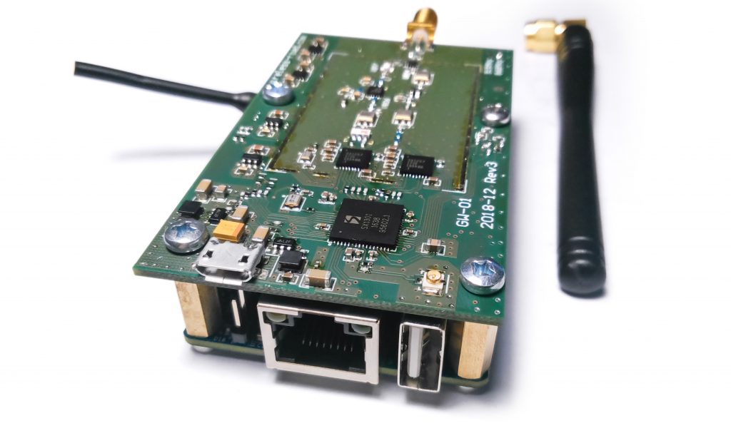
M2M IOT has launched a GW-01 LoRaWAN gateway based on an Orange Pi Zero H2+ SBC which supports outdoors installations. The GW-01 integrates the Zero H2+ with an 8-channel LoRaWAN board based on Semtech’s SX1301 LoRa concentrator. The $120 “GW-01” LoRaWAN gateway runs Linux on an Orange Pi Zero H2+ SBC as well as an 8-channel LoRaWAN board. The GW-01 is a modified version of the GW-01 RPI add-on for the Raspberry Pi, and also the all-in-one GW-01 PoE gateway that features Power-over-Ethernet support that runs on i.MX6 ULL. The three products ship out with an open-source Linux stack, with LoRa gateway and packet-forwarder software pre-installed on the board. The GW-01 gateway clocks in at 868MHz or 915MHz LoRa frequencies, and has -139 dBm sensitivity. It has a 2.5 km range when obstructed by buildings, or up to 10 Km in an open space. The GW-01 measures at 80 х 50 х 20mm minus the supplied antenna and has a 0 to 70°C temperature.
The GW-01 runs OpenWrt, or Armbian on the Orange Pi Zero H2+, and features an Allwinner H2+. The H2+ SoC enables 4x Cortex-A7 cores @ 1.2GHz and a Mali-400 MP2 GPU. The Zero H2+ offers a meager 256MB DDR3 RAM, and the available display interface is an AV-out header. Available also is a single USB 2.0 host, micro-USB OTG with 5V power input, and 10/100 Ethernet ports. The board also has a microSD slot, WiFi, and a 26-pin header that supports early Raspberry Pi boards.
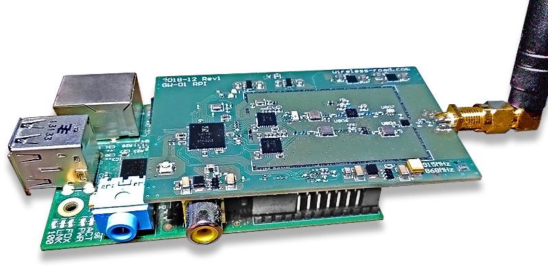
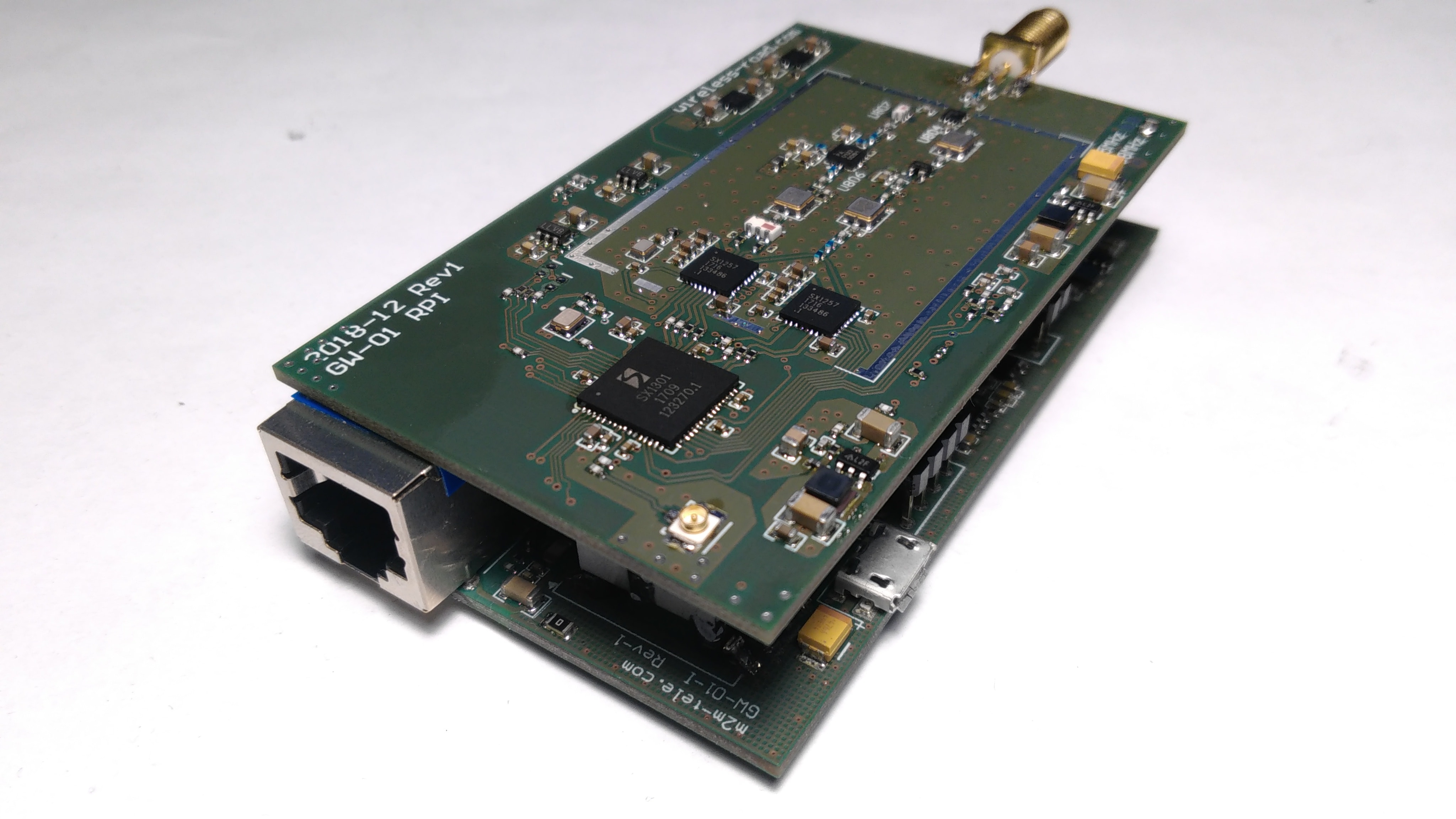
GW-01 RPI
The Zero H2+ board on the GW-01 has 8MB serial flash instead of the 2MB. The reason for the increment is to incorporate the 4.5MB OpenWrt image. One thing I see that stands out about the SBC is that it has lower power consumption and a lower price ( $8.50) than any of the latest RPI boards. For prototyping purposes, M2M IOT recommends TheThingsNetwork or its own cloud.m2m-tele server. The GW-01 RPI and GW-01 PoE have similar specs with the GW-01, with the exception of the PoE model having a wider -35 to 70°C range. The GW-01 RPI can operate with any Raspberry Pi 2 or 3 board.
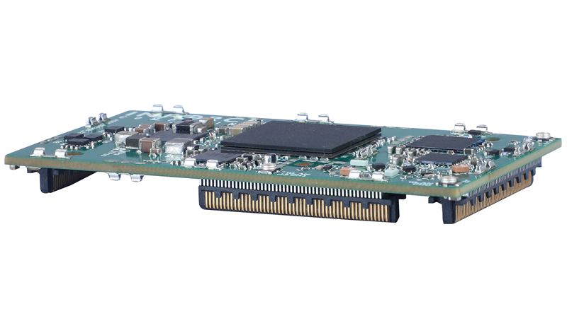
GW-01 PoE
The RPI and PoE models have an 80 x 50mm footprint like the GW-01, and the SBC on the PoE model also adds 20mm on the vertical, and they both ship with antennas. The PoE model also runs on OpenWrt like the GW-01, while the RPI shield runs Raspbian. The GW-01 PoE is a standalone product which integrates a homegrown SBC based on NXP’s power-sipping, single Cortex-A7 based i.MX6 ULL SoC. It features an Ethernet port with 48V PoE support for easier installation.
The GW-01 is available for $120, the RPI model is $95, and the PoE model is $245. More information may be found on the M2M IOT website and GitHub page, and also the shopping pages for the GW-01, GW-01 RPI, and GW-01 PoE.
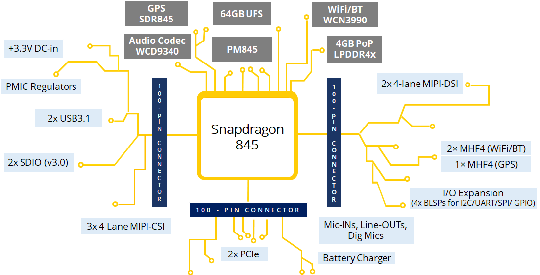
A production ready micro SoM based on Snapdragon™ 845 SoC architected for Artificial Intelligence and Immersion
The compact sized Inforce 67X1 SOM’s multiple MIPI-CSI interfaces and on-device artificial intelligence (AI) allows users to capture cinema-grade videos and blur the lines between physical and virtual worlds. The product’s enhanced hardware and software capabilities bring high-performance, true-to-life cinematic video capture, with 64x more high-dynamic range color information for video capture and playback on Ultra HD Premium displays, compared to the previous generation. This massive boost in color information includes 10-bit color depth for over one billion shades of colors that can be displayed to the wide Rec. 2020 gamut for brilliant 4K/Ultra HD @60 fps videos. The Adreno GPU enables room-scale 6 degrees of freedom (6DoF) with simultaneous localization and mapping (SLAM)—for features such as wall-collision detection. Snapdragon 845 also introduces “Adreno foveation,” which substantially reduces power consumption, improves visual quality and boosts XR application performance, as compared to the previous generation. All these features make it ideal for manufacturers to develop SWaP constrained devices in the immersive multimedia space, wearables, portable healthcare and connected cameras’ domain.
The Snapdragon 845 platform has processor advancements that offer an improved user experience
Qualcomm Kryo 385 CPU: Manufactured in 2nd gen 10nm LPP, optimized across 4 performance and 4 efficiency cores for higher performance.
Hexagon™ 685 DSP: Designed to support supports sophisticated, on-device AI processing, delivering richer camera, voice, XR and gaming experiences.
Adreno™ 630 VPS: Featuring room-scale 6DoF with SLAM, Adreno Foveation, and significantly improved graphics rendering and video processing, the Visual Processing Subsystem(VPS) comprising the GPU, VPU and DPU provides a larger-than-life immersive experience. It includes support for Vulkan 2/OpenGL ES 3.2/OpenCL.
Dual 14-bit Spectra™ 280 ISPs support up to 16MP each for simultaneous concurrent cameras
Qualcomm® AI Engine: The 3rd generation AI Platform enables on-device intelligence and simplifies how you take pictures and videos. It also enables enhanced features like camera bokeh, more true to life XR, gaming, and long lasting battery life. The Snapdragon core hardware architectures are engineered to run AI applications quickly and efficiently.
Specifications
Based on the Snapdragon™ 845 processor (SDA845) manufactured in 10nm FinFET process technology
Customized Kryo™ ARMv8 compliant 64-bit Octa-core CPUs arranged in two dual-clusters, running at 2.8GHz (Gold) and 1.8GHz (Silver) each
Adreno™ 630 VPS with 64 bit addressing and designed for significantly improved graphics and efficient rendering as compared to the previous generation
Hexagon™ 685 DSP with dual-Hexagon vector processor designed for on-device AI processing, low-power audio, XR/gaming and computer vision processing
Spectra™ 280 camera (dual) Image Signal Processors (ISPs) to support up to 24MP single or 16MP@60 fps dual cameras
PROCESSING POWER, MEMORY, AND STORAGE
Qualcomm® Snapdragon™ 845 (SDA845 SoC) processor
4GB on-board LPDDR4X RAM
64GB UFS ROM
1x µSD card v3.0 interface
USB-C on USB 3.1/gen1 + USB-SS
Intelligent scalable power management for superior energy efficiencies through PMIC
802.11n/ac 2X2 MU-MIMO 2.4GHz/5GHz WiFi & BT/LE 5.x via WCN3990
GPS/GLONASS via SDR660G
1x 1-lane PCIe Gen 2 and 1x 1-lane PCIe Gen 3
Audio Lineouts, HPH and Mic-In from integrated PMIC codec
POWER, MECHANICAL, AND ENVIRONMENTAL
Power: +3.8V/6A Input
Dimensions: 50mm x 28mm
Operating Temp: -20C to +85 C (Extended Temp SKU)
Storage Temp: -20 to 85 C
Relative Humidity: 5 to 95% non-condensing
RoHS and WEEE compliant
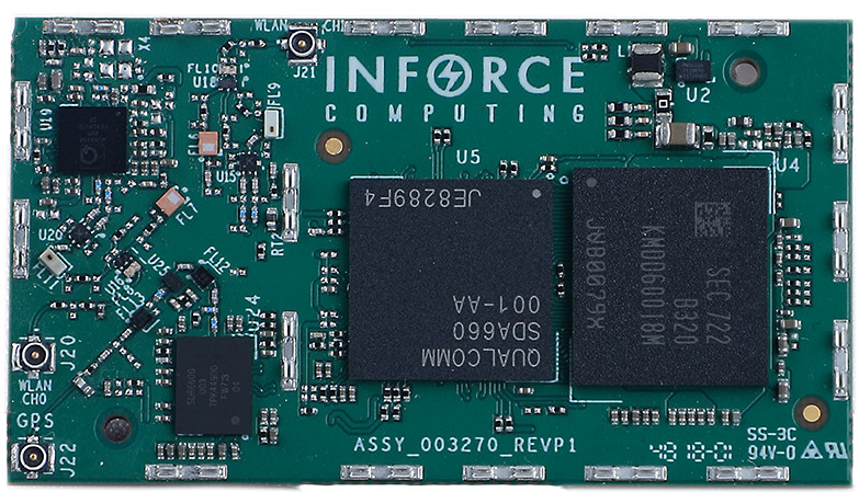
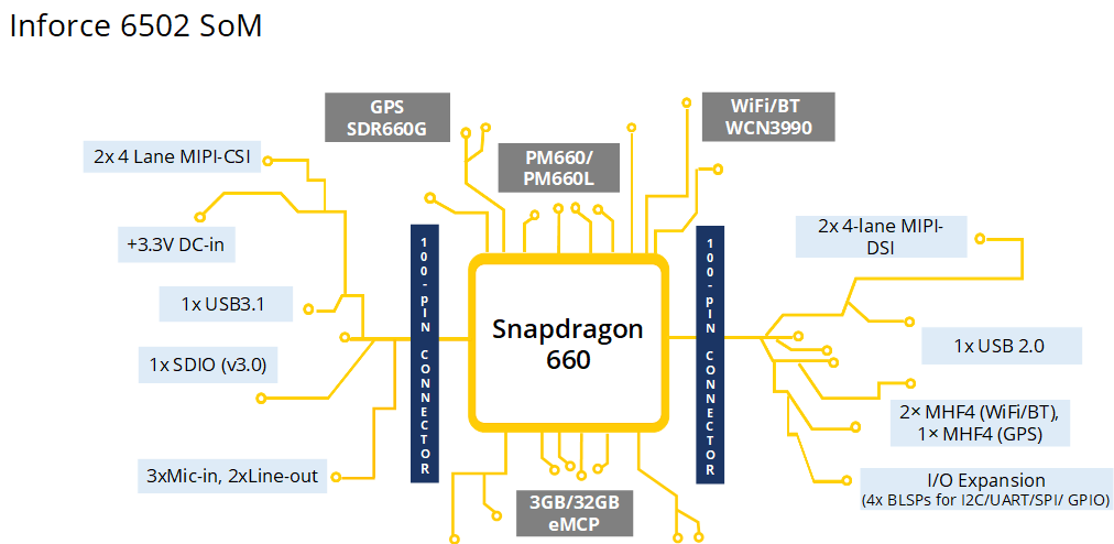
– Inforce 6502
A production ready micro SoM based on Snapdragon™ 660 SoC with stereoscopic depth sensing and deep Learning capabilities
The compact sized Inforce 6502 SOM offers multiple MIPI-CSI interfaces with which depth perception use-cases like proximity detection, semantic segmentation, autonomous driving and facial recognition can be enabled with ease on a system built with this product. The product’s enhanced hardware and software capabilities for on-camera deep learning and video analytics, 4K HEVC video encoding and advanced features for robust hardware-based security make it ideal for manufacturers to develop SWaP constrained devices in the wearables, portable healthcare and connected cameras’ domain including bodycams and IP security cameras.
The Snapdragon 660 platform has processor advancements that offer an improved user experience
Qualcomm Kryo 260 CPU: Higher performance with independent efficiency and power clusters, each designed to optimize for a unique UX
Hexagon™ 680 DSP: Vector eXtensions (HVX) designed to support Caffe2 and Tensorflow for machine learning and image processing
Adreno™ 512 GPU: Vulkan/OpenGL ES 3.2/OpenCL support and lifelike visuals coupled with efficient rendering of advanced 3D graphics
Dual 14-bit Spectra™ 160 ISPs support up to 16MP each for simultaneous concurrent cameras
Qualcomm® AI Engine: The Snapdragon core hardware architectures are engineered to run AI applications quickly and efficiently.
Specifications
Based on the Snapdragon™ 660 processor (SDA660) manufactured in 14nm FinFET process technology
Customized Kryo™ ARMv8 compliant 64-bit Octa-core CPUs arranged in two dual-clusters, running at 2.2GHz (Gold) and 1.8GHz (Silver) each
Adreno™ 512 GPU with 64 bit addressing and designed for upto 30% better graphics and efficient rendering as compared to Adreno 506
Hexagon™ 680 DSP with dual-Hexagon vector processor (HVX-512) designed for 787MHz for low-power audio and computer vision processing
Spectra™ 160 camera (dual) Image Signal Processors (ISPs) to support up to 24MP single or 16MP dual cameras
PROCESSING POWER, MEMORY, AND STORAGE
Qualcomm® Snapdragon™ 660 (SDA660 SoC) processor
3GB on-board LPDDR4 RAM
32GB eMMC ROM
1x µSD card v3.0 interface
USB-C on USB 3.1/gen1 + USB-HS
Intelligent scalable power management for superior energy efficiencies through PMIC
802.11n/ac 2X2 MU-MIMO 2.4GHz/5GHz WiFi & BT/LE 5.x via WCN3990
GPS/GLONASS via SDR660G
Audio Lineouts, HPH and Mic-In from integrated PMIC codec
POWER, MECHANICAL, AND ENVIRONMENTAL
Power: +3.3V/6A Input
Dimensions: 50mm x 28mm
Operating Temp: -20C to +85 C (Extended Temp SKU)
Storage Temp: -20 to 85 C
Relative Humidity: 5 to 95% non-condensing
RoHS and WEEE compliant
More information
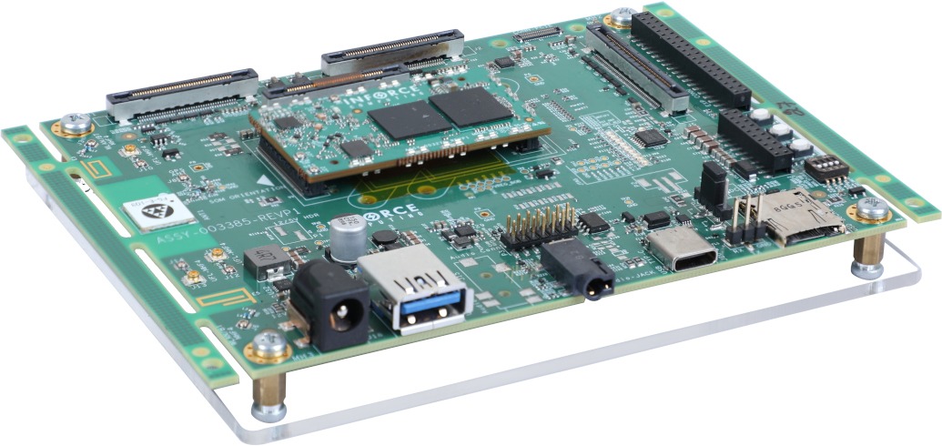
The Inforce 6701 and Inforce 6502 modules are available now. The Inforce 6701 sells for $285 or $300 (extended temp) and the Inforce 6502 lists only the $208 commercial temp SKU, both in single quantities. The SoM +ACC-1C20 Carrier is available as the IFC6701-00-P1 (6701) and IFC6502-00-P1 (6502) Reference Designs and sell for $600 and $500, respectively. It’s unclear what the prices are for the other Inforce 6502 carrier boards.
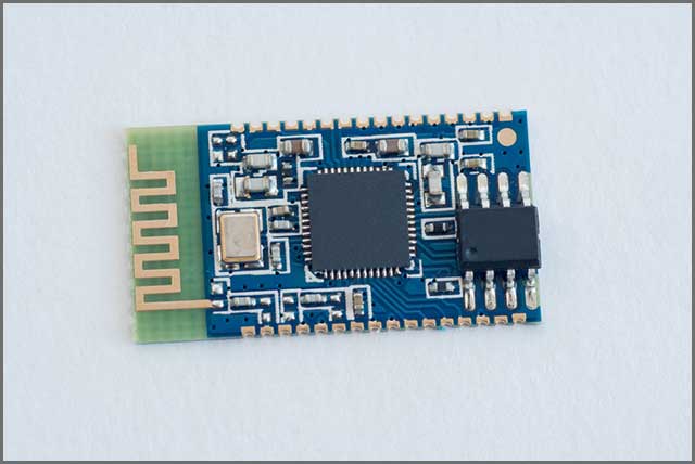
SHIJIAZHUANG, China, July 9, 2019 (Newswire.com) –OurPCB, a multi-national PCB Manufacturing and PCB Assembly company, today published a Guide on ‘Bluetooth Circuit Board-How To Count As a High-Quality Bluetooth Board‘
It has six chapters that cover every detail about Bluetooth Circuit Board.
The publication is available on the https://www.ourpcb.com/bluetooth-circuit-board.html section of the company’s website for free. It is a simple guide authored by the OurPCB technical team to help both beginners and professionals have a better understanding of Bluetooth Circuit Board.
“OurPCB is always working on creating and publishing articles and topics that are truly valuable to the customers that can help customers solve problems. The articles and bits of knowledge which can solve customers’ problems and needs when designing and manufacturing PCBs or seeking PCBA services; this is the value of company’s existence,” said Mr.Hommer, OurPCB General manager.
Among the key subjects on Bluetooth Circuit Board include:
Bluetooth Circuit Board: This section gives a brief overview of the definition of Bluetooth and the principles of Bluetooth technology, and introduces information about the components of the Bluetooth board.
Types of Applications of Bluetooth: This section details some typical applications of Bluetooth boards, including Wireless Headsets and Earphones, Cordless Keyboards and Mouse.
Bluetooth Module: This section provides an overview of the advantages of the Bluetooth Module and introduces a common Bluetooth module type: the HC05 Bluetooth Serial Port Protocol (SPP) module. Also presents the application range of the Bluetooth module.
Bluetooth Speaker Circuit Board: This section details the Bluetooth Speaker Circuit Board information.
Bluetooth Transmitter Circuit Board: This section focuses on the Bluetooth transmitter board with three critical components – regulation voltage, sensor data and wireless transmission and related information.
Bluetooth Receiver Board: This section briefly describes the role of the Bluetooth Receiver and Bluetooth Receiver Board.
Finally, the focus of this article is to let you know that you have to maintain professional standards while assembling a Bluetooth circuit board; otherwise, the functionalities, range and other features will suffer. If you have any needs or questions, feel free to contact us. There is a lot of knowledge about PCB on the website to help you know more about what you want when purchasing PCB and PCBA services.
About OurPCB
OurPCB is a multi-national PCB Manufacturing and PCB Assembly company that provides Global service and support while utilising its Chinese manufacturing capabilities.
Our Assembly factory has received ISO9001 certification. For bare PCB manufacturing, we also received ISO and UL certifications.
Media Contact: Contact Person: Hommer Zhao (General Manager)
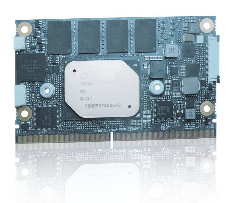
Kontron, a leading global provider in IoT/Embedded Computer Technology (ECT), has introduced the new SMARC-sXAL4 module. The module is available with either Intel Atom®, Intel® Pentium® or Intel® Celeron® processors of the latest generation. With dimensions of only 82mm x 50mm, it can be used flexibly, and the E2 version is designed for use in an extended temperature range from -40°C to +85°C. Thanks to its large number of interfaces, significantly improved computing power and excellent performance-per-watt ratio, the SMARC-sXAL4 is ideally suited for use in industrial IoT and Industry 4.0 systems.
The SMARC-sXAL4 will be available in five versions: either with DualCore or QuadCore processors. Together with the SMARC-sXAL (E2), which supports DDR3 ECC memory, Kontron now offers customized modules for every purpose based on all current IoT-enabled embedded processors from Intel®. The SMARC-sXAL4 has up to eight GB LPDDR4 memory down RAM, up to two 1000 MBit/s Ethernet, up to four PCIe x1 and four USB 2.0 ports (alternatively: one USB OTG), as well as two USB 3.0 ports. Up to 128 Mbytes of eMMC (MLC) onboard memory serve as mass storage. The new module also has a SATA 6 GB/s and four serial interfaces (two RX and TX ports each), one HD Audio and one I2S, five I2C, two SPI, two MIPI CSI and twelve GPIO, one HDMI, one DP++ and one Dual Channel LVDS interface (on request also for eDP displays). Users also benefit from the high graphics performance of Intel® HD Gfx Gen9. Up to three 4K displays can be controlled independently.
The SMARC-sXAL4 uses the operating systems Windows® 10, Enterprise, Windows 10 IoT, Linux and VxWorks. The VCC voltage of the module is 5V; a wide-range voltage input has been omitted
The new Kontron SMARC-sXAL4 (E2) supports the Kontron APPROTECT security solution based on Wibu-Systems CodeMeter®. Kontron APPROTECT Licensing also enables new business models such as ‘pay-per-use’ and time-based trial versions.
The SMARC-sXAL4 is available in the following standard variants:
SMARC-sXAL4 N4200 4G/8S SMARC with Intel® Pentium® N4200, 4GB LPDDR4 memory down, 8GB eMMC pSLC, commercial temperature
SMARC-sXAL4 N3350 2G/4S SMARC with Intel® Celeron® N3350, 2GB LP-DDR4 memory down, 4GB eMMC pSLC, commercial temperature
SMARC-sXAL4 E3930 4G/8S SMARC with Intel Atom® x7 E3930, 4GB LPDDR4 memory down, 8 GB eMMC pSLC, industrial temperature
SMARC-sXAL4 E3940 4G/16S SMARC with Intel Atom® x7 E3940, 4GB LPDDR4 memory down, 16 GB eMMC pSLC, industrial temperature
SMARC-sXAL4 E3950 8G/32S SMARC with Intel Atom® x7 E3950, 8GB LPDDR4 memory down, 32 GB eMMC pSLC, industrial temperature
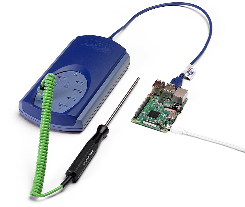
Pico Technology has announced what the company believes to be the first ever fully supported software package for the popular and inexpensive Raspberry Pi single-board computer.
Optimized and tested on the new Raspberry Pi 4, and the current 3B and 3B+ on Raspbian Stretch, the PicoLog 6 data logging software package provides a visual, easy-to-use interface allowing engineers to quickly set up simple or complex acquisitions and record, view and analyze data. It’s the same fully functioning software that runs on Windows, macOS and Linux.
Coupled with a Raspberry Pi, this new PicoLog 6 package expands the flexibility and opens the door for Pico’s data loggers to be used in new and different ways. Users c an now connect the logger to the Pi and remove the keyboard, mouse and video to make an inexpensive stand-alone logger storing its captured data locally on a Pi SD-Card. Connecting the board by WiFi or Ethernet, one can internet-enable the Pico logger which can then be accessed remotely using an open-source VNC server and viewer freely available. Using the Power over Ethernet (PoE) capability on the Raspberry Pi 3B+ paired with the PoE PiHAT not only eliminates the need for an external power supply and powered USB hub, it also internet-enables the logger at the same time.
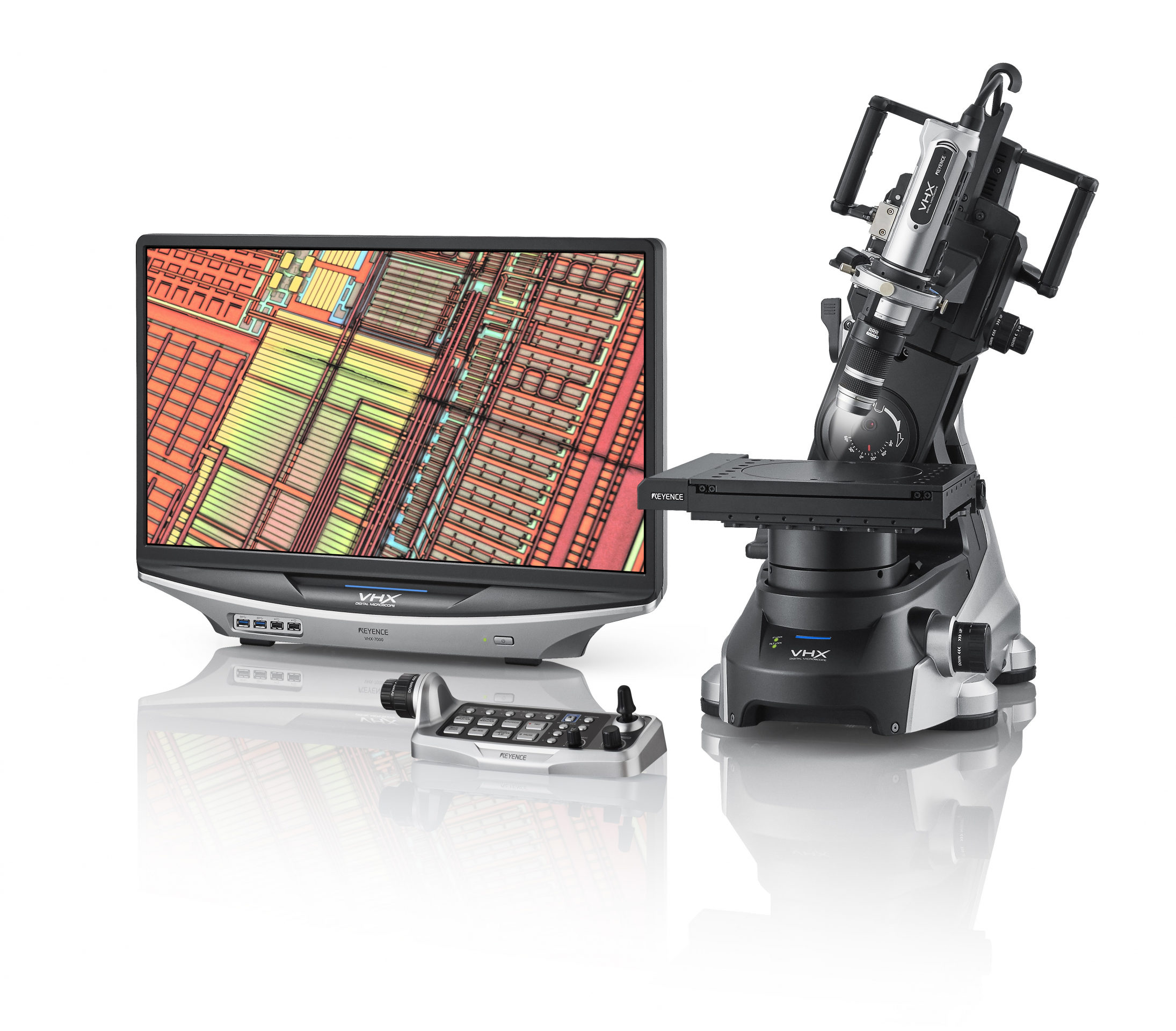
The VHX-7000 digital microscope, which is now available in the UK and Ireland, offers high magnification and accuracy, and is both versatile and easy to use. With a wide array of functions and features, the VHX-7000 is the best way to future-proof microscopy requirements for years to come.
Using the Keyence VHX-7000, both 2D and 3D measurements can be performed with ease. Just one microscope is required to take roughness, contamination, grain size and a host of other measurements. Observation is provided with an optimal balance of brightness and clarity. Moreover, images can be easily saved on the 1 TB hard drive (enough capacity for millions of images) and shared over LAN or USB. Similarly, reports can be automatically created and shared.
Features such as ‘Optical Shadow Effect Mode’ make subtle contours stand out (in colour) and enhance uneven surfaces and stains at the push of a button. By combining a 4K CMOS image sensor with a new multi-directional lighting variation technique, the VHX-7000 can deliver images that rival an SEM (scanning electron microscope).
Even novice users can easily capture high-resolution images. The operator simply places the target on the stage, and everything else – including alignment and focus adjustment – is fully automatic. A handheld controller puts functions such as magnification switching at the fingertips of the user.
Among major features is high-speed image stitching, which occurs automatically upon command. In addition, by capturing multiple images while the stage is moving, 3D data capture and stitching can take place simultaneously, which makes it possible to view and analyse the overall contours of the target.
In terms of 3D measurement, even when the target has an uneven surface, a fully-focused image is obtained instantly, composed from multiple images with varying focus positions. The new fully integrated head offers the highest picture quality in the VHX series. What’s more, observation using the VHX-7100 fully integrated head can be carried out automatically at magnifications from 20x to 6000x without manually changing the lens.
A combination of optics, digital camera, electronics, software, and a wide choice of motorised XYZ and rotary stages, means users can perform complete inspection and analysis using a single system. As a result, applications traditionally performed on stereoscopic, metallurgical, measuring and even SEM microscopes can easily be transferred to the VHX-7000.
For automotive and other metal-based industries, on-machine automated contamination and cleanliness analysis compliant with ISO 16232 standards is made possible for large area measurement. Higher magnification and high-resolution imaging combine with one-click auto measurement for quality inspection in semiconductor and electronics industries, while automatic area measurement with object counting can be deployed for grain structure analysis in pharmaceuticals, metallurgy or other demanding sectors.
Ultimately, the new VHX-7000 all-in-one digital microscope will streamline and simplify quality inspection across all industries, while simultaneously providing outstanding image results. Keyence is currently offering a no-obligation, on-site demonstration of the system.
A detailed brochure on the full range of functions, features and options available is available at: www.keyence.co.uk/vhx7000launch
Advantech, a global leading provider of intelligent IoT systems and embedded platforms, is pleased to announce the latest addition to its ARK-1000 series: the ARK-1220, a compact DIN-Rail fanless embedded box PC for industrial and/or outdoor environments. The ARK-1220 adopts Intel Atom® E3940 QC processors with front accessible I/O ports on single bezel—targeting applications such as machine automation, intelligent factories, in-cabinet equipment integration, and IoT gateways. To enable effective device management, the ARK-1220 comes pre-loaded with Advantech’s new IoT device management App: WISE-PaaS/DeviceOn. This App includes hardware security certification and parameter settings required by the relevant application domain to help simplify the initial deployment phase and subsequent management.
Intelligent Management and Security Support for Industrial Environments
WISE-PaaS/DeviceOn was the first to adopt the zero–touch technology connection for software and hardware integration, allowing users to monitor real-time health status and send software and firmware updates over-the-air (OTA) on-site. For system security, the ARK-1220 utilizes the Trusted Platform Module (TPM) 2.0 function by request and supports BitLocker under Windows 10 IoT. Moreover, McAfee and Acronis are integrated into WISE-PaaS/DeviceOn for anti-virus protection and invaluable data recovery and backup. Our hardware and software solutions help users simplify equipment management via an easy, efficient, and secure systematic method that fits different industrial and/or outdoor environments.
Ruggedized and Compact DIN-Rail Fanless Design
The ARK-1220 is powered by Intel Atom® E3940 Quad Core SoC, with up to 1.8 GHz with turbo burst on. The dual channel memory sockets support a maximum of up to 8GB DDR3L 1866 MHz SO-DIMM. Designed for rugged environments, the ARK-1220 supports a -30 ~70°C operating temperature range with 0.7 m/s air flow that is ideal for working outdoors. Its wide ranging power input of 12V – 28V DC-in is suitable for use in environments with fluctuating or unstable power supply. The ARK-1220 supports an array of functional I/O ports, including 4x USB 3.0, 2x LAN, and 2x COM ports placed on front panel. Its compact dimensions are appropriate for applications installed in limited space but requiring I/O flexibility and enhanced performance.
Dual 4K Display with Immersive Graphics and Media Performance
ARK-1220 offers dual 4K ultra HD independent displays with a resolution of up to 3840 x 2160 pixels at 30 Hz. The Gen9 graphics engine runs on low power while enhancing media processing capability with video encoding and playback performance that offers a 40% improvement compared to the previous generation. The ARK-1220 empowers manufacturers to access clearer analysis and management via panel displays or interactive displays in intelligent factories and machine automation processes. For more information, visit the Advantech website or contact your local sales office.
˙ Intel Atom® E3940 Quad Core SoC turbo burst up to 1.8 GHz
˙ DIN-rail system with essential I/O ports on front-side bezel
˙ Dual HDMI display up to 4K ultra HD resolution
˙ Compact design of (W x H x D) 53.5 x 158 x 114 mm (2.11″ x 6.22″ x 4.49″)
˙ 1 x full-size mPCIe with SIM holder and 1 x M.2 2230 for WIFI
˙ 12V ~ 28V wide range power input
˙ -30 ~ 70°C extended operating temperature
˙ Advantech WISE-PaaS/DeviceOn support
In the last tutorial, we examined How to connect your IoT devices to the Arduino IoT Cloud, and we saw how to send and receive data, from and to the cloud. With multiple cloud solutions available for IoT devices, there might be a need for you to work with one not as traditional as the Arduino IoT cloud. To help you prepare, for today’s tutorial, we will look at how to build IoT devices that interact with the Adafruit IO.
Adafruit IO represents Adafruit’s desire to continually develop solutions that support makers and hardware enthusiasts in general. It is essentially an integrated cloud service for IoT devices designed primarily, like most other cloud services, to retrieve and store data. However, to make things more suitable for use by its target audience, Adafruit included features that facilitate real-time data visualization using graphs, gauges, etc., Email/webhook notifications, and Control of devices from the internet. It also features IFTTT and zapier integrations which give us the ability to interact with 100s of web services like RSS feeds and Twitter. It comes with a limited but wholly sufficient free plan as well as a paid plan which gives full unrestricted access for around 10$/month.
IoT devices typically perform tasks involving; either sending data to the cloud or receiving data commands from the cloud, as such, in today’s tutorial will have a two-part tutorial to cover both aspects. For the first part, we will obtain temperature, humidity, atmospheric pressure, and light intensity data from the environment and send it to Adafruit IO where it will be displayed on a dashboard and updated every 2s. To provide an offline view of the data, we will use a 1.44 Adafruit TFT LCD display. You can check some of our past tutorials using the 1.44″ TFT display to better understands how it works.
The second part of the tutorial will be used to demonstrate how to control the device from the cloud. We will set up an on/off button on the cloud which when pressed, will show the corresponding text on a display.
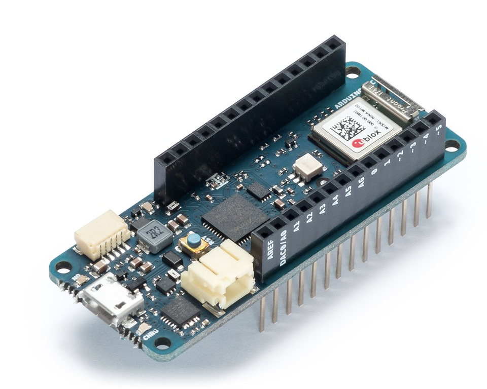
To make all of this happen, at the center of today’s project is the Arduino MKR WiFi 1010 board. It is one of the latest boards of the Arduino line and is a significantly improved version of the MKR 1000 WiFi. It’s equipped with an ESP32 module made by U-BLOX with the aim of speeding up and simplifying the development of WiFi-based IoT applications, leveraging on the flexibility and low power consumption of the ESP32 module.
Getting Started with Adafruit.io IoT Cloud Platform – [Link]
In the last tutorial, we examined How to connect your IoT devices to the Arduino IoT Cloud, and we saw how to send and receive data, from and to the cloud. With multiple cloud solutions available for IoT devices, there might be a need for you to work with one not as traditional as the Arduino IoT cloud. To help you prepare, for today’s tutorial, we will look at how to build IoT devices that interact with the Adafruit IO.
Adafruit IO represents Adafruit’s desire to continually develop solutions that support makers and hardware enthusiasts in general. It is essentially an integrated cloud service for IoT devices designed primarily, like most other cloud services, to retrieve and store data. However, to make things more suitable for use by its target audience, Adafruit included features that facilitate real-time data visualization using graphs, gauges, etc., Email/webhook notifications, and Control of devices from the internet. It also features IFTTT and zapier integrations which give us the ability to interact with 100s of web services like RSS feeds and Twitter. It comes with a limited but wholly sufficient free plan as well as a paid plan which gives full unrestricted access for around 10$/month.
IoT devices typically perform tasks involving; either sending data to the cloud or receiving data commands from the cloud, as such, in today’s tutorial will have a two-part tutorial to cover both aspects. For the first part, we will obtain temperature, humidity, atmospheric pressure, and light intensity data from the environment and send it to Adafruit IO where it will be displayed on a dashboard and updated every 2s. To provide an offline view of the data, we will use a 1.44 Adafruit TFT LCD display. You can check some of our past tutorials using the 1.44″ TFT display to better understands how it works.
The second part of the tutorial will be used to demonstrate how to control the device from the cloud. We will set up an on/off button on the cloud which when pressed, will show the corresponding text on a display.
To make all of this happen, at the center of today’s project is the Arduino MKR WiFi 1010 board. It is one of the latest boards of the Arduino line and is a significantly improved version of the MKR 1000 WiFi. It’s equipped with an ESP32 module made by U-BLOX with the aim of speeding up and simplifying the development of WiFi-based IoT applications, leveraging on the flexibility and low power consumption of the ESP32 module.
Arduino MKR WiFi 1010
The board is made up of three main blocks:
SAMD21 Cortex-M0+ 32bit Low Power ARM MCU
U-BLOX NINA-W10 Series Low Power 2.4GHz IEEE® 802.11 b/g/n Wi-Fi
ECC508 Crypto Authentication
The MKR WIFI 1010 includes a 32-bit computational power, the usual rich set of I/O interfaces associated with Arduino boards, and a low power Wi-Fi with a Cryptochip for secure communication using SHA-256 encryption. All these features can easily be programmed using Arduino Software (IDE) for code development and programming.
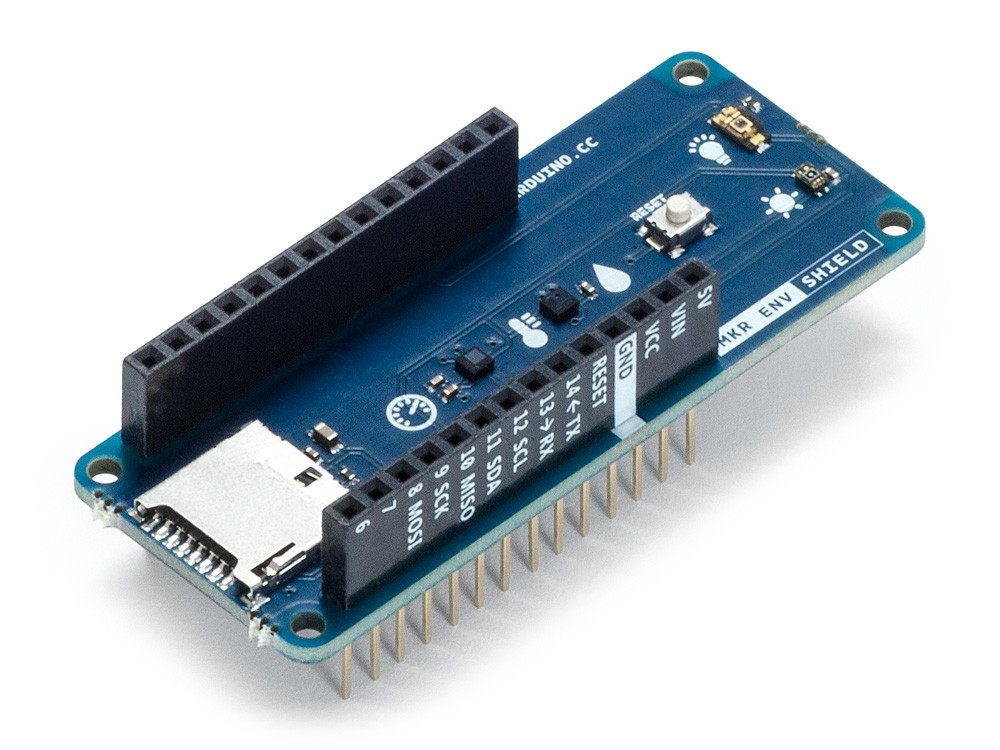
Other key components we will use include the Arduino MKR ENV shield and the Arduino MKR RGB Shield.
Arduino MKR ENV Shield
Arduino MKR ENV shield allows the MKR Arduino board series to acquire environmental data via a plethora of inbuilt sensors including;
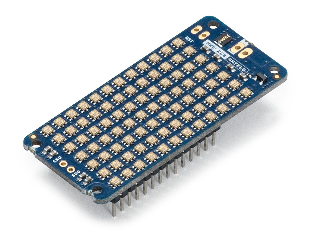
The Arduino MKR RGB, on the other hand, is made up of an array of super bright LEDs which, with the use of a superb library, allows the display of static and scrolling text in minutes. It will be used to display a text corresponding to the state of the on/off button on the Adafruit IO dashboard.
Arduino MKR RGB Shield
At the end of this tutorial, you would know how to build IoT devices that are based on the Adafruit IoT cloud and for those who may be new to the MKR series of boards, you would know, developing basic and complex projects based on them.
Required Components
The following components are required to build both parts of this tutorial;
All of these components can be bought from the Arduino store or from electronics components sales platforms like Seeed Studio, and Aliexpress.
Schematics
As mentioned during the introduction, there are two parts to this tutorial as such, we will have two schematics.
Schematic 1: Sending data to the cloud
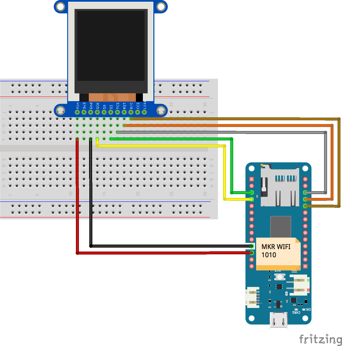
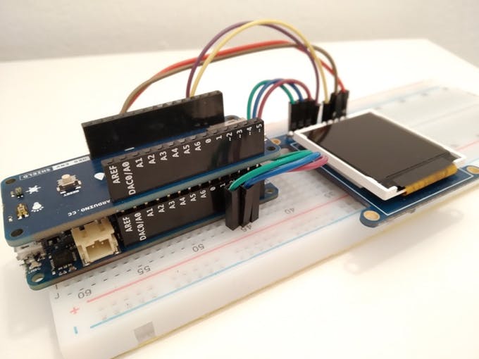
For the first part, we will use the Arduino MKR WiFi 1010 board, the MKR ENV Shield, and the 1.44″ TFT Display. The MKR ENV Shield, like the name implies, comes as a shield and is plugged on top the MKR WiFi 1010, leaving us with just the connections between the MKR WiFi 1010 and the 1.44″ TFT display. Connect as shown in the fritzing schematics below.
Schematics
To make connections easier to follow, the pin to pin map of the connection between the MKR WiFi 1010 and the 1.44″ TFT is shown below.
After connecting the components, your setup should look like the one in the image below.
Part 1 Components Assembly
Schematic 2: Receiving Data from the Cloud
For the second half of the project (Receiving Data from the cloud), we will use Arduino MKR WiFi 1010 and the Arduino MKR RGB Shield. While adjustments could be made to accommodate the sensors on the ENV shield, we will do it this way to keep things short and simple.
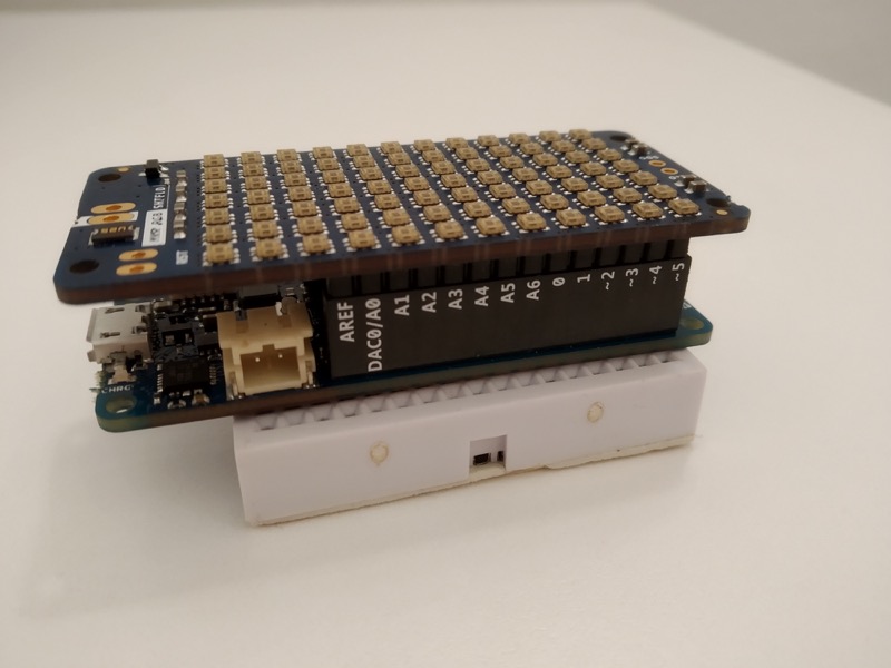
Just like the MKR ENV Shield, the RGB Shield also comes as a shield and should be plugged on the MKR WiFi 1010 as shown in the image below.
Part 2 Connection
Since you will most likely use the same MKR WiFi 1010 for both parts, you can complete the code upload of one part before connecting the second part.
Programming
Just like we did under the schematics, we will also split this into two parts. The first part will be for programming the board to send the data as we highlighted initially, and the second part will be to receive data from the IoT Cloud and display on the RGB shield. For both parts, we will use the WIFINNA library and the Adafruit IO Rest API. You could also choose to use the Adafruit IO library.
Part 1: Sending data to the Cloud
Before we start writing the code, we need to create the “feeds” on Adafruit.io to which the data will be reported. The feeds will be placed in a group to make it easy for us to manage and send data with a single command. Follow the steps below to do this;
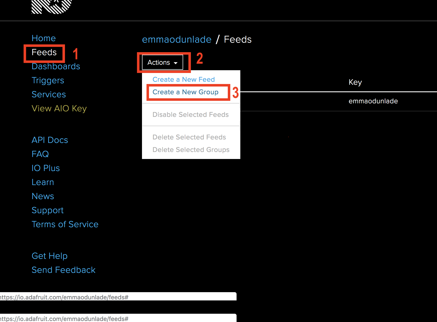
-Logging in should take you to the Adafruit IO home page. Click the feeds button, it should take you to a page with a list of all the feeds that have been created on your account. Click on the “actions” button and select “create a new group” from the dropdown menu.
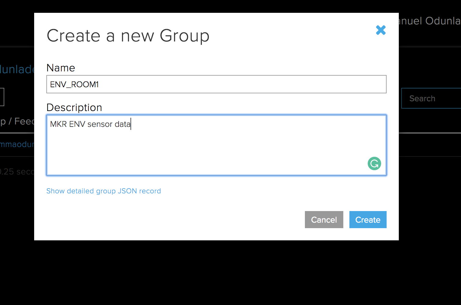
-Enter the name of the group and a description and click the create button.
Create a group to house all feeds
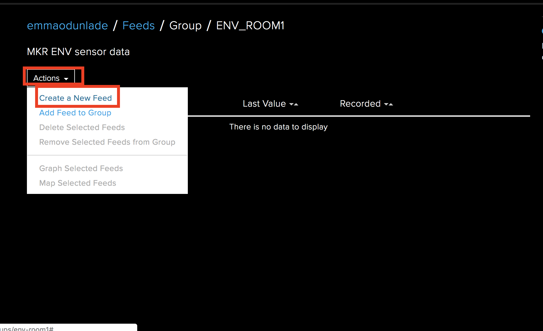
-With the group created, we need to add four feeds under it, each one for the parameters we will monitor. Click on the group you just created, when the new page opens, click on the action button again and select “Create a new feed“.
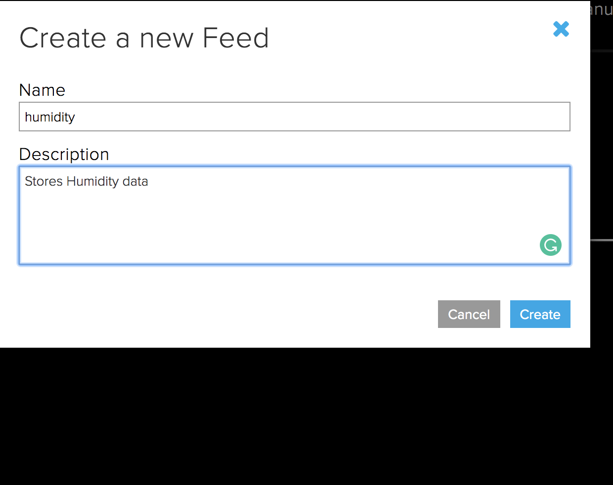
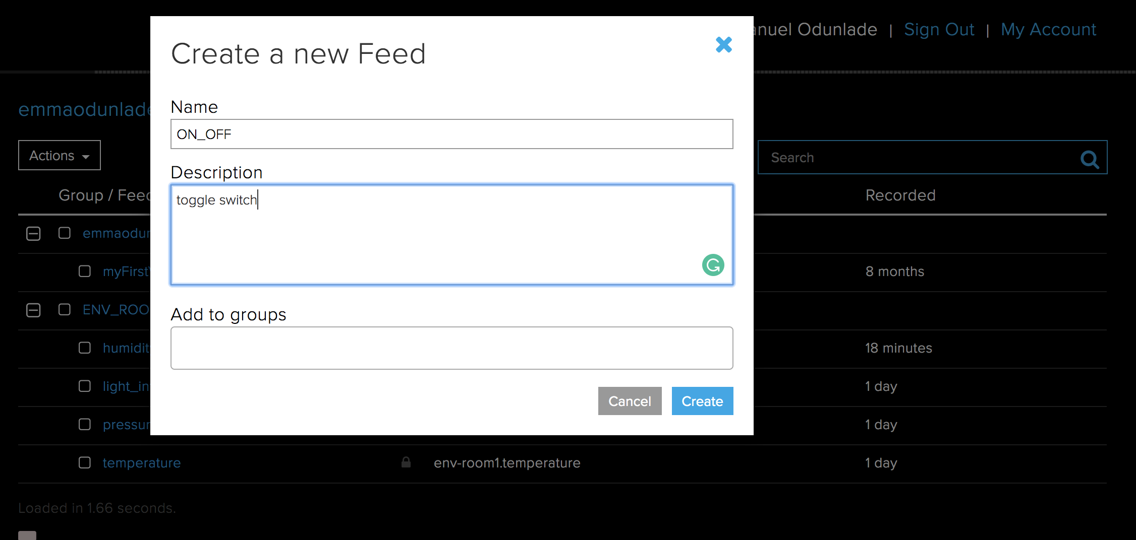
-In the dialogue box that opens, enter the name of the feed, and a description then click the create button.
Creating a New Feed
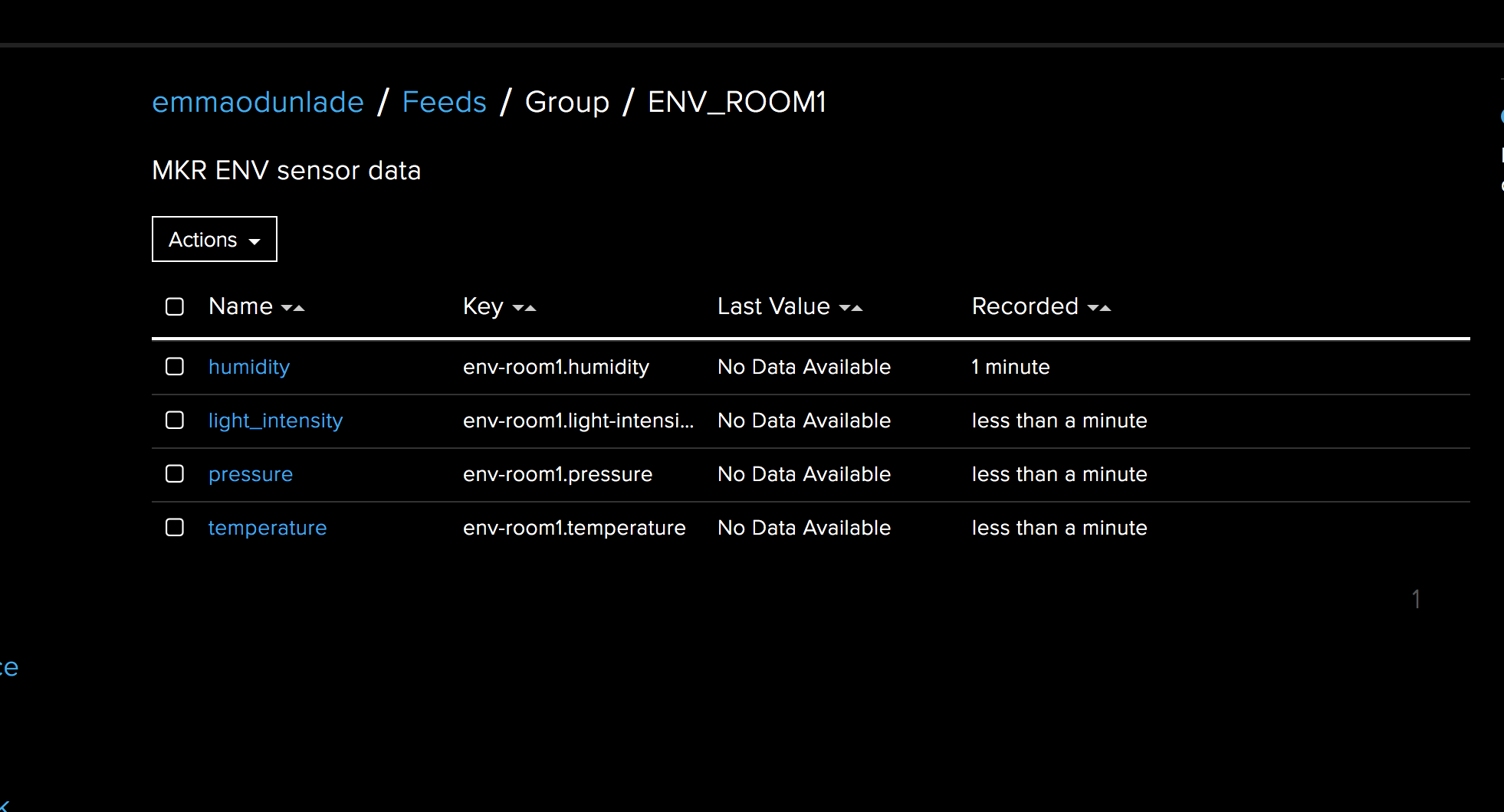
-Repeat step 4 and 5 for all the other parameters; temperature, humidity, Light Intensity, and pressure. When done, the group feed should look at the image below.
All Feeds Created
By clicking on each of the feeds and scrolling down, a history of data stored in the feed can be seen, however, to make it more interactive and user-friendly, we will create a dashboard to host the data from all the four feeds. To do this, follow the steps below.
-Click on the dashboard button just below feeds on the right-hand side of the IO page, just below feeds.
-It will open a list of all the dashboards you have created. If you have less than four(the free access to Adafruit IO allows just four dashboards), click on the action button at the top of the page and select “create a new dashboard“.
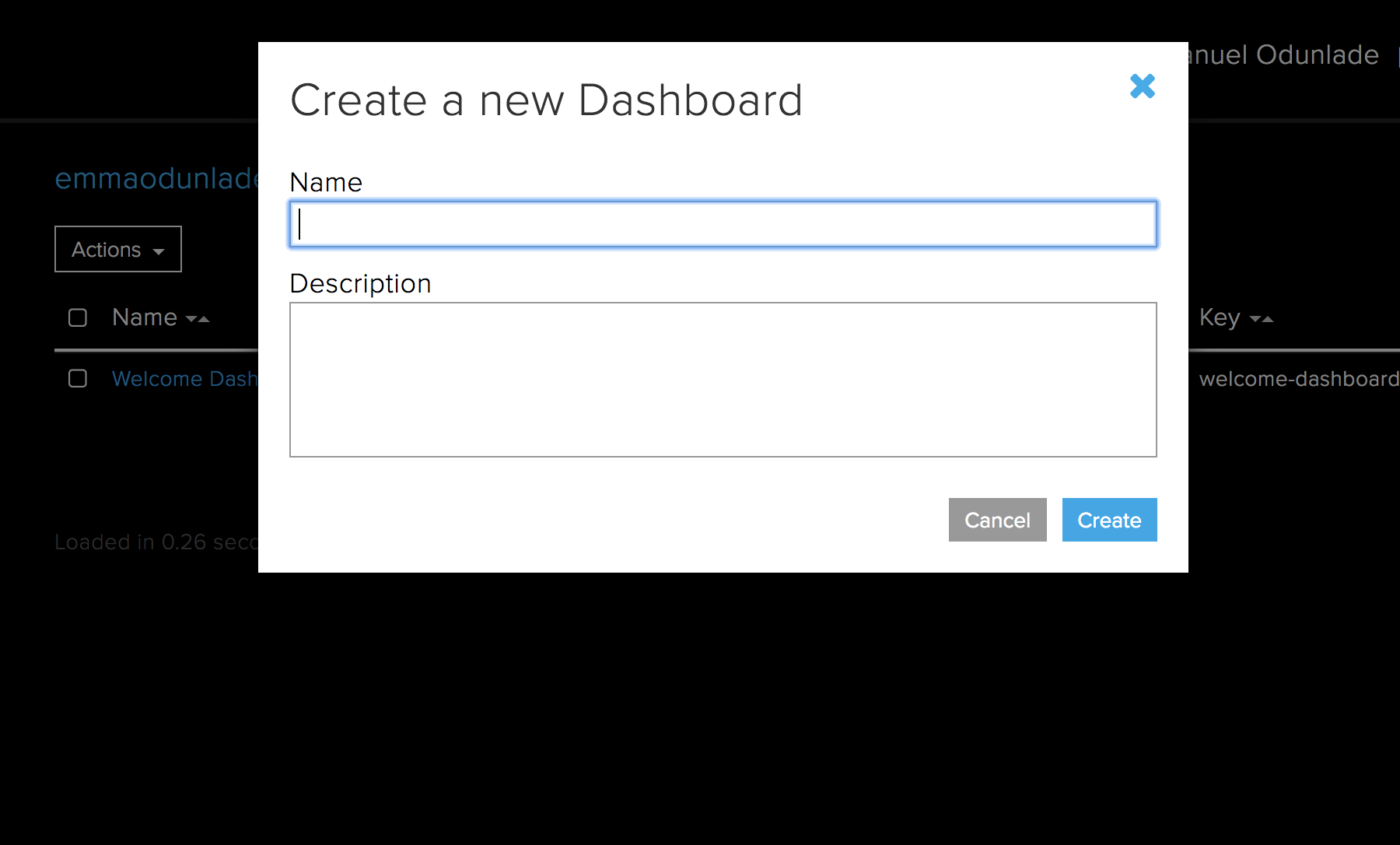
-Enter the name and description of the dashboard in the dialogue box that opens and click the “create” button.
Create a New Dashboard
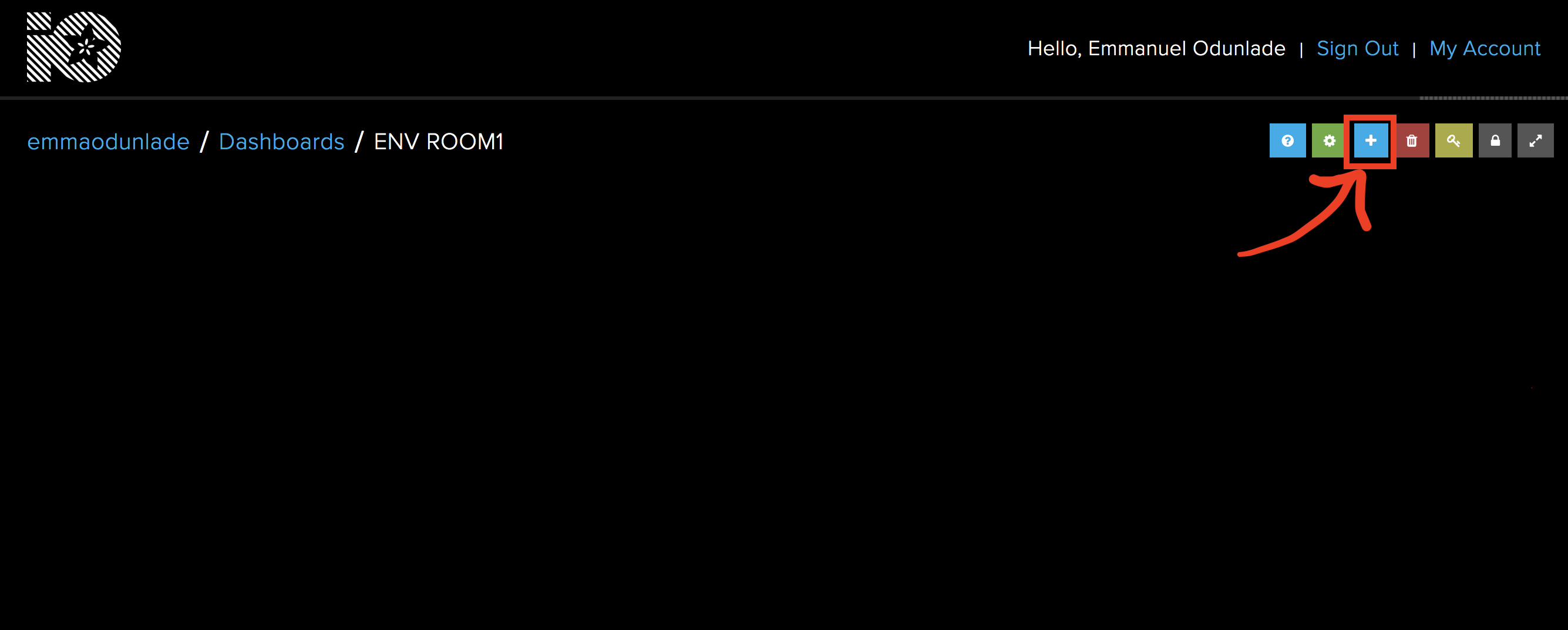
-Click on the dashboard you have created, it should open a new window. On the window, click on the “+” Icon to start adding blocks (widgets) to the dashboard.
Add Blocks to Dashboard
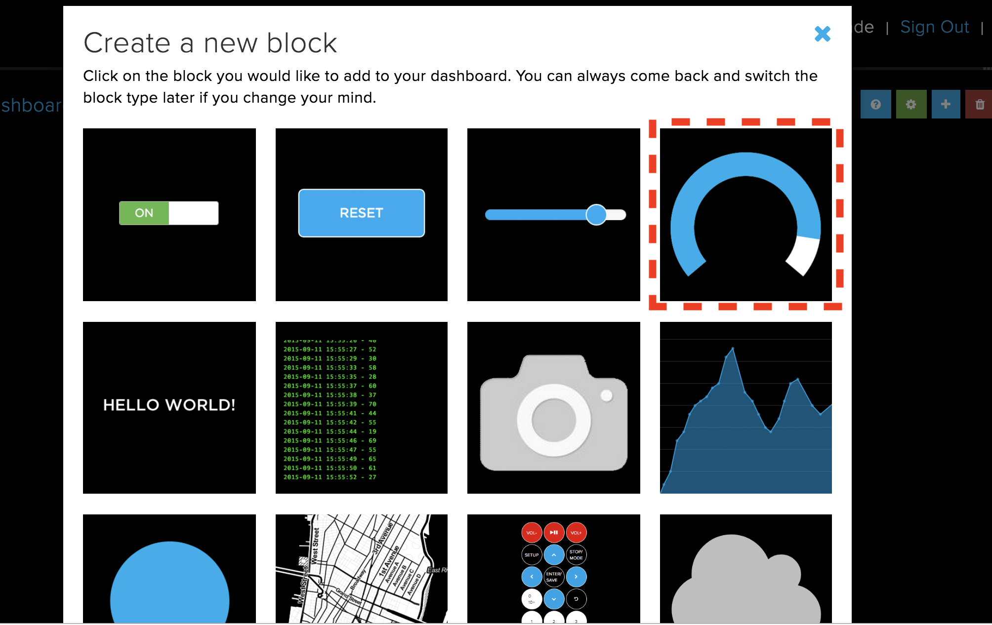
-For this tutorial, we will use a gauge widget to represent each of the parameters to be monitored. Click on the Gauge block.
Select the Gauge Widget/Block
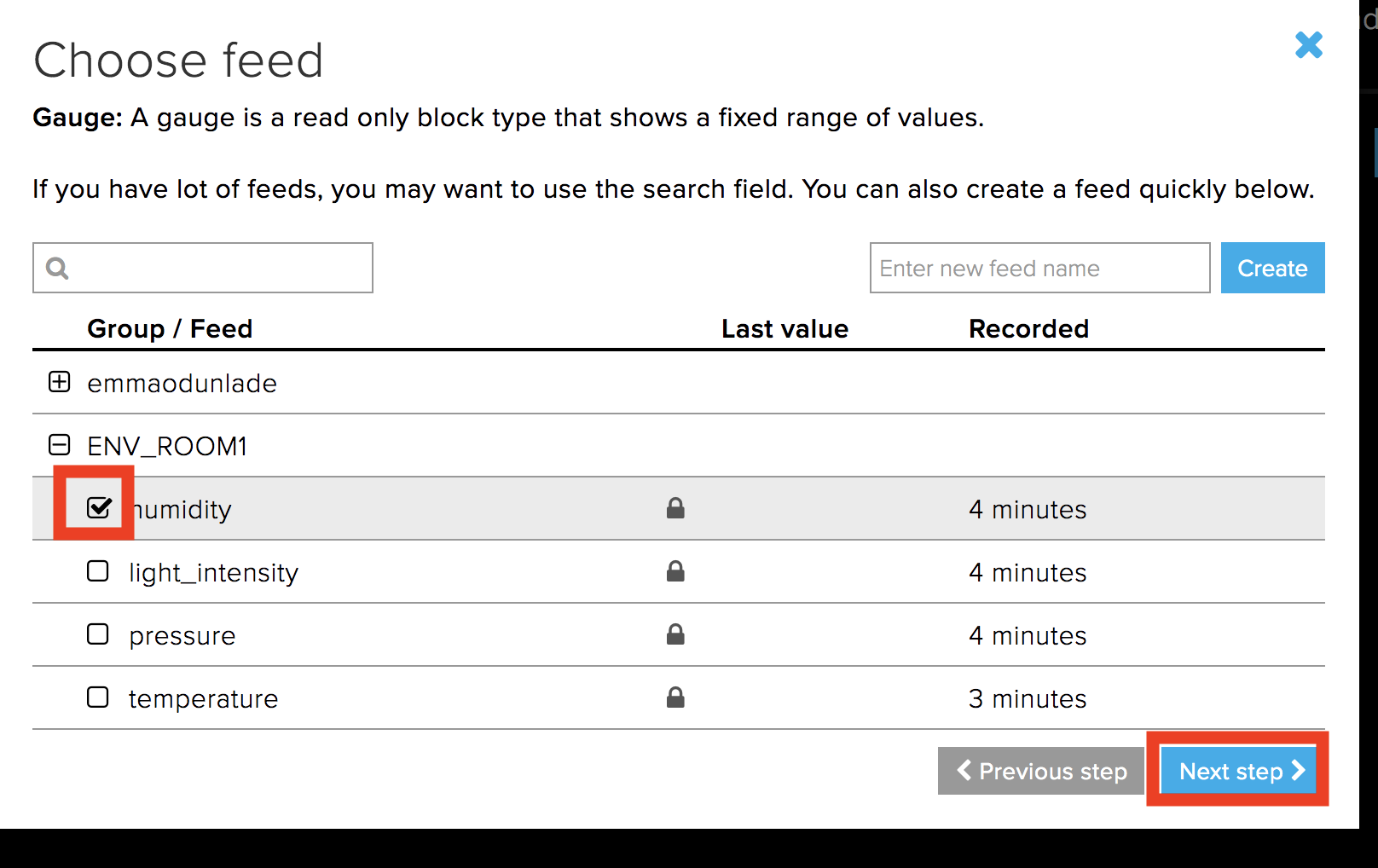
-Clicking on the gauge block will open a dialogue block to enable you to set the properties of the block. Select the feed to whose data will be displayed on that block and hit the next button.
Select Widget Feed
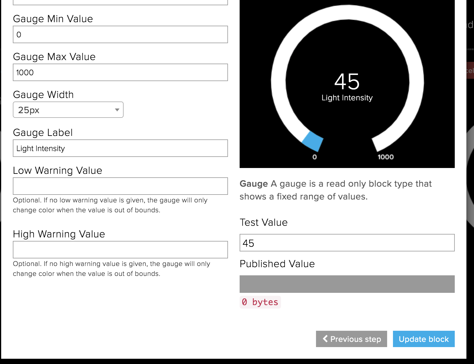
-On the next page, Enter the label you want to be displayed on the gauge (best if its the same name as the field for easy referencing), set the min and max values as desired, then hit the create block button.
Set Widget parameters
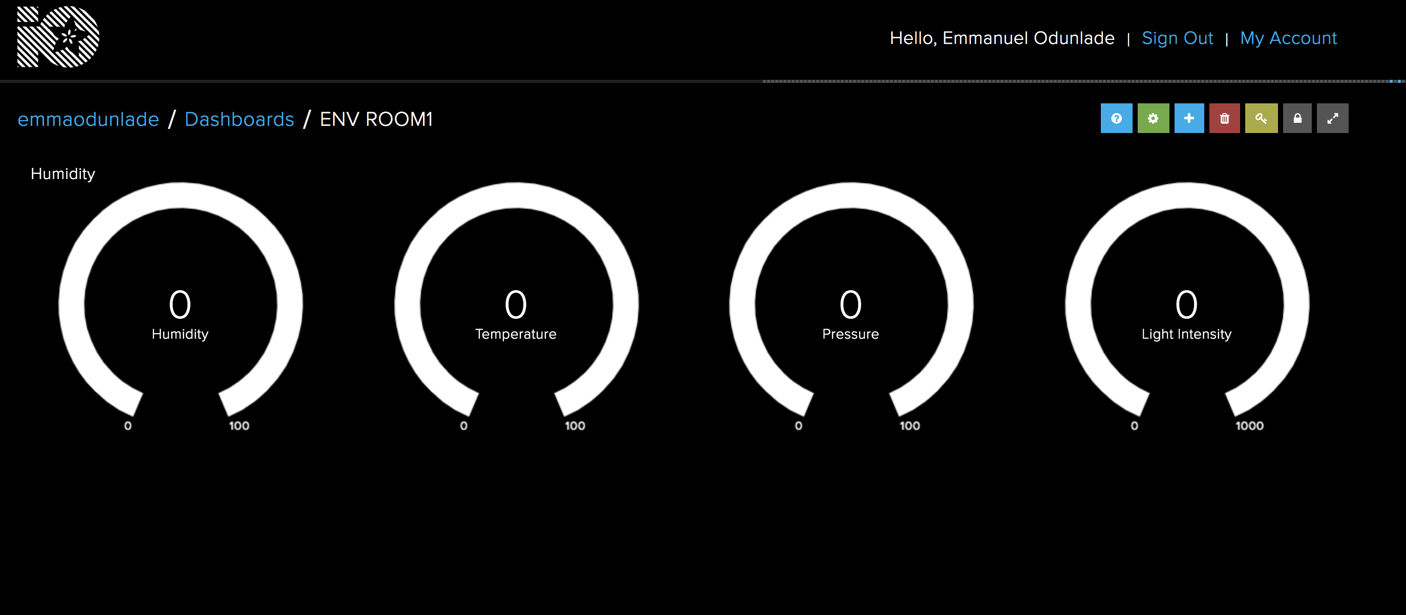
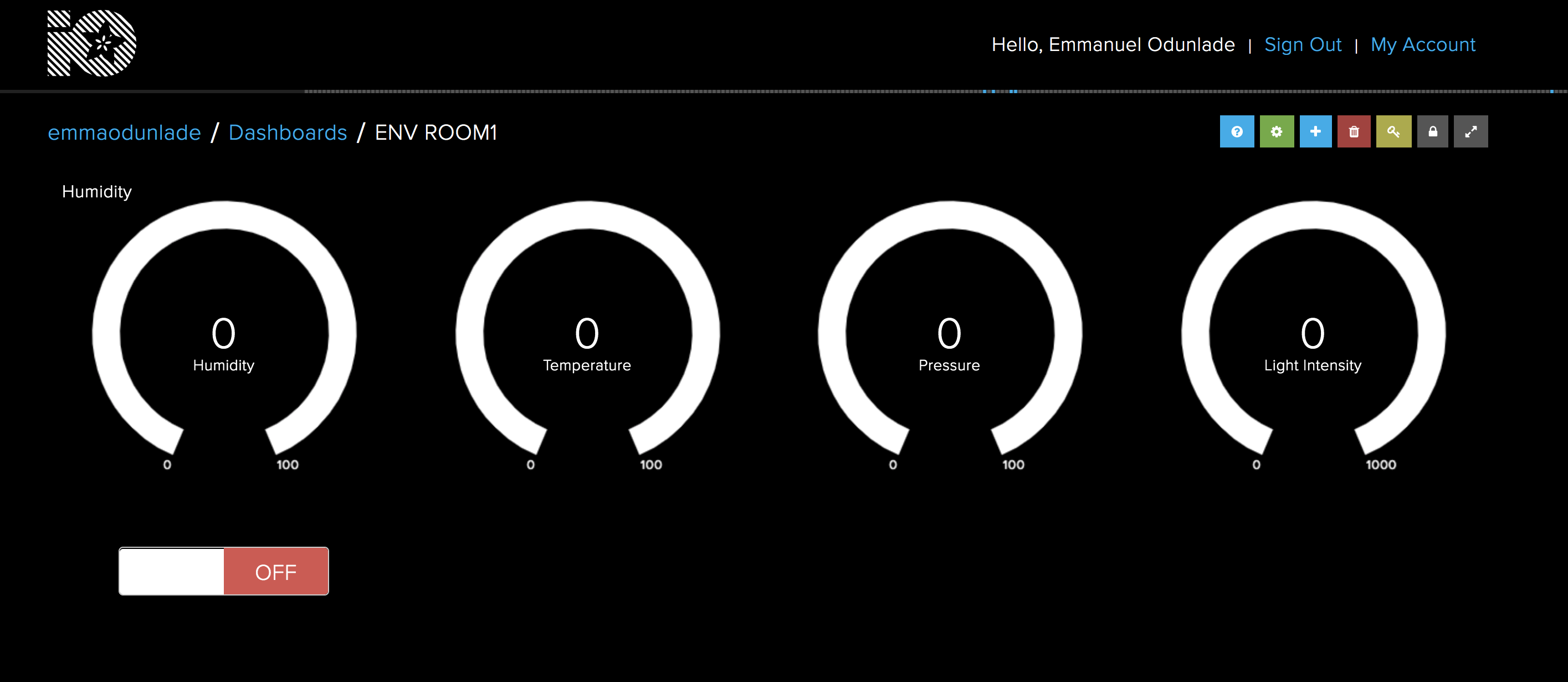
-Repeat step 4 – 7 for the remaining feeds. Your Dashboard when done should look like the one in the image below. The blocks can be rearranged by clicking the settings icon and dragging the blocks until they are side by side. Since no data has been uploaded to it yet, all values will be at zero.
Dashboard Preview
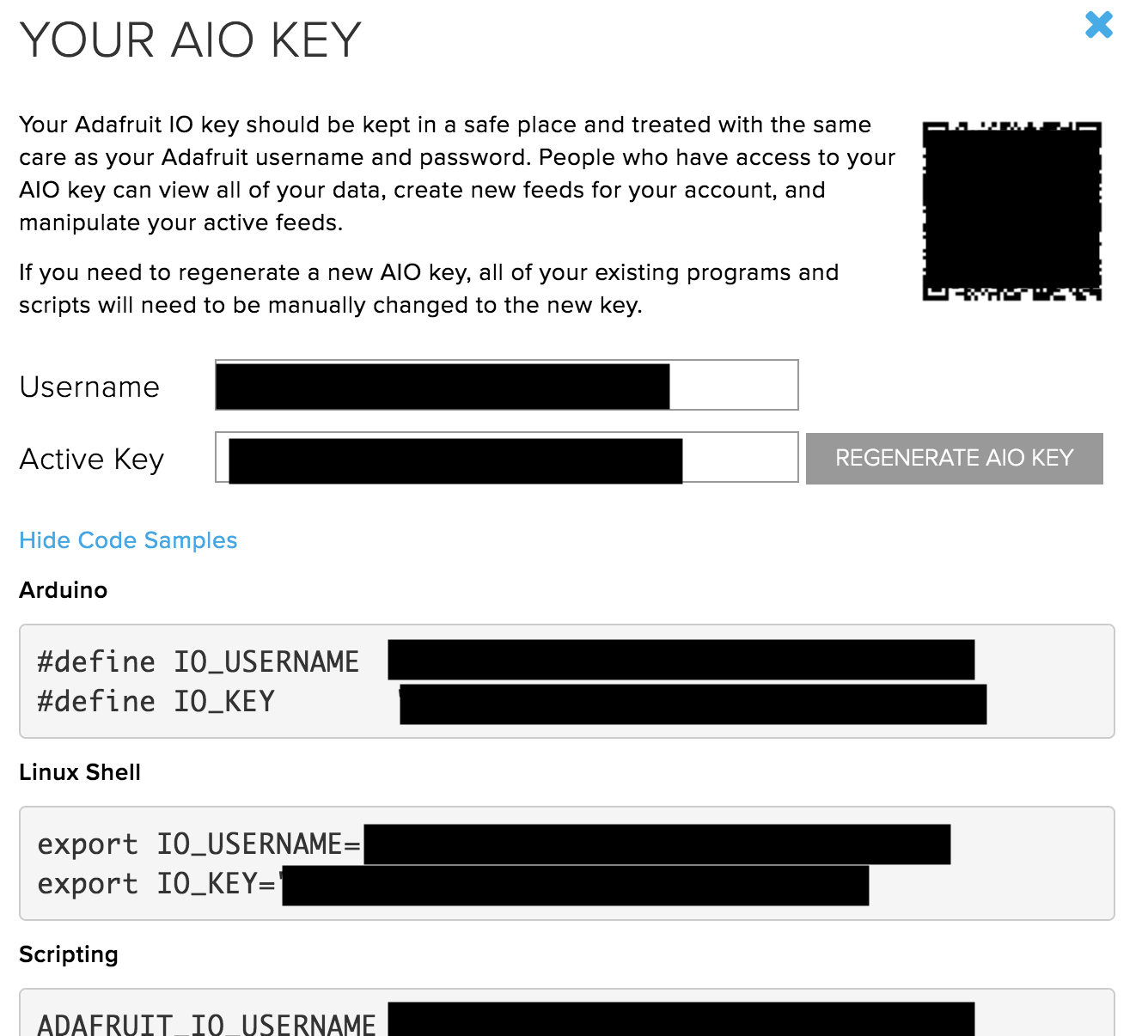
With that done, we proceed to obtain the last element of the Adafruit IO that will be used in our code; the AIO key. The AIO key is an alphanumeric key that allows secure communication between your device and Adafruit IO. Go to your IO home page, just below services after dashboard you will see the view AIO key button. Click on it to open a page similar to the image below. Copy the AIO key for later use.
Get AIO Key
With this done, we are now ready for the code.
As mentioned earlier, we will use the WIFININA library along with the Adafruit IO Rest API but for this part, in addition to those libraries, we will also use the Arduino JSON library, the Adafruit GFX library,the Adafruit ST7735 library, and the MKR ENV library. The Arduino JSON library will be used to group the data when sending to Adafruit IO, while the ST7735 library facilitates communication with the 1.4″ TFT display, and the GFX library makes it easy to display graphics and the text on the TFT. The MKR ENV reduces the amount of code needed to obtain data from the ENV shield.
As usual, I will do a quick run through the code to explain the concepts involved.
We start the code by including all the libraries that we will use. To make the code modular and clean, a header file (called arduino_secrets.h) was created (in the same folder as the sketch) to store passwords and sensitive data like the AIO key and wifi credentials, include this too along with other libraries that have been mentioned.
Next, we declare the pins of the Arduino to which the Chip Select (CS), Reset (RST) and DC pins of the TFT LCD are connected (as described under the schematics section) and create an instance of the ST7735 library with the variables mentioned above as arguments.
Next, we create the variables to hold the WiFi credentials, the server address, posting interval and a “last connection time” variable to help determine when the next update to the server is due. We also initialize the WiFi Client Library.
char ssid[] = SECRET_SSID;         // your network SSID (name)
char pass[] = SECRET_PASS;         // your network password (use for WPA, or use as key for WEP)
int status = WL_IDLE_STATUS;
char server[] = "io.adafruit.com"; // name address for Adafruit IOT Cloud

unsigned long lastConnectionTime = 0;              // last time you connected to the server, in milliseconds
const unsigned long postingInterval = 7000;       // delay between updates, in milliseconds
Next, we create the variables that will be used to store the data to be obtained from the ENV Shield.
We start by initializing Serial communication to help with debugging the code, setting the baud rate to 9600. After this, we initialize the display, change the screen color to black, initialize the ENV shield, and use the connectToWiFi() function to connect to the specified SSID.
void setup() {

  Serial.begin(9600);
  //while (!Serial); // wait for serial port to connect. Needed for native USB port only

  // Init ST7735R chip, green tab
  tft.initR(INITR_144GREENTAB);

  tft.fillScreen(ST77XX_BLACK);

  // Init MKR ENV shield
  if (!ENV.begin()) {
    Serial.println("Failed to initialize MKR ENV shield!");
    while (1);
  }

  connectToWIFI();

}
Next, we write the voidloop() function.
The code for the voidloop() is simple thanks to the libraries we are using and a few functions.
We start the voidloop() by checking if the posting interval has elapsed as the Adafruit IO has a specified interval of seconds between data uploads for free access. If the time has elapsed, we then use the readsensor() function to obtain data from the ENV shield and call the displayValuesOnTFT() function to display the values. The displayValuesOnSerial() function is used to print the values on the serial monitor for debugging and the httpRequest() function is used to send the data to the cloud.
void loop() {

 // if 7 seconds have passed since your last connection,
  // then connect again and send data:
  if (millis() - lastConnectionTime > postingInterval)
  {
    readSensors();
    displayValuesOnTFT();
    displayValuesOnSerial();
    httpRequest(); // send data to Cloud
  }

}
To take a closer look at these functions,
The readsensors() functions contain code to probe the ENV shield for each of the parameters we intend to measure and equate it to the corresponding variable name.
The HTTP request function combines the values from the readsensor() function together in a JSON format (Key and value pair) and sends to Adafruit IO. The status of the data upload is displayed on the TFT and the variable; lastConnectionTime is updated to determine when the next data is sent.
void httpRequest()
{


/*
 * https://io.adafruit.com/api/docs/#operation/createGroupData
 *
 * POST /{username}/groups/{group_key}/data
 *
 * JSON:
 *
{
  "location": {
    "lat": 0,
    "lon": 0,
    "ele": 0
  },
  "feeds": [
    {
      "key": "string",
      "value": "string"
    }
  ],
  "created_at": "string"
}
 */

  const size_t capacity = JSON_ARRAY_SIZE(3) + 3*JSON_OBJECT_SIZE(2) + 2*JSON_OBJECT_SIZE(3) + 130;
  StaticJsonDocument<capacity> doc;

   // Add the "location" object
  JsonObject location = doc.createNestedObject("location");
  location["lat"] = 0;
  location["lon"] = 0;
  location["ele"] = 0;

  // Add the "feeds" array
  JsonArray feeds = doc.createNestedArray("feeds");
  JsonObject feed1 = feeds.createNestedObject();
  feed1["key"] = "temperature";
  feed1["value"] = _temperature;
  JsonObject feed2 = feeds.createNestedObject();
  feed2["key"] = "humidity";
  feed2["value"] = _humidity;
  JsonObject feed3 = feeds.createNestedObject();
  feed3["key"] = "pressure";
  feed3["value"] = _pressure;
  JsonObject feed4 = feeds.createNestedObject();
  feed4["key"] = "light_intensity";
  feed4["value"] = _lux;


  // close any connection before send a new request.
  // This will free the socket on the Nina module
  client.stop();

  Serial.println("\nStarting connection to server...");
  if (client.connect(server, 80))
  {
    Serial.println("connected to server");
    // Make a HTTP request:
    client.println("POST /api/v2/" IO_USERNAME "/groups/" IO_GROUP "/data HTTP/1.1");
    client.println("Host: io.adafruit.com");
    client.println("Connection: close");
    client.print("Content-Length: ");
    client.println(measureJson(doc));
    client.println("Content-Type: application/json");
    client.println("X-AIO-Key: " IO_KEY);

    // Terminate headers with a blank line
    client.println();
    // Send JSON document in body
    serializeJson(doc, client);

    // note the time that the connection was made:
    lastConnectionTime = millis();

    testdrawtext(5,120,"data sent to Cloud!", ST77XX_WHITE,1);
    Serial.println("data sent!");

  } else {
    // if you couldn't make a connection:
    testdrawtext(10,120,"connection failed!", ST77XX_WHITE,1);
    Serial.println("connection failed!");
  }


}
The displayValuesOnTFT() function, on the other hand, is used to display the values from the readsensor() function on the TFT display. The function starts by converting all the values to the string after which they are displayed using the testdrawtext() function.
The testdrawtext() function takes several arguments including the screen coordinates where the text is to be written, the text/value to be written, color and font size. We have covered the use of the st77xx displays in several tutorials, you can check them out to learn more about the functions.
The complete code for this part is available below and also attached under the download section. You can either jump straight to the demo section from here or follow part 2.
Part 2: Receiving Data from the cloud
As mentioned during the introduction, for this second part, we will examine how you can send commands from the cloud to the device to initiate actions. For this example, we will toggle a switch on the dashboard and a text(on/off) corresponding to the state of the switch will be displayed on the RGB shield.
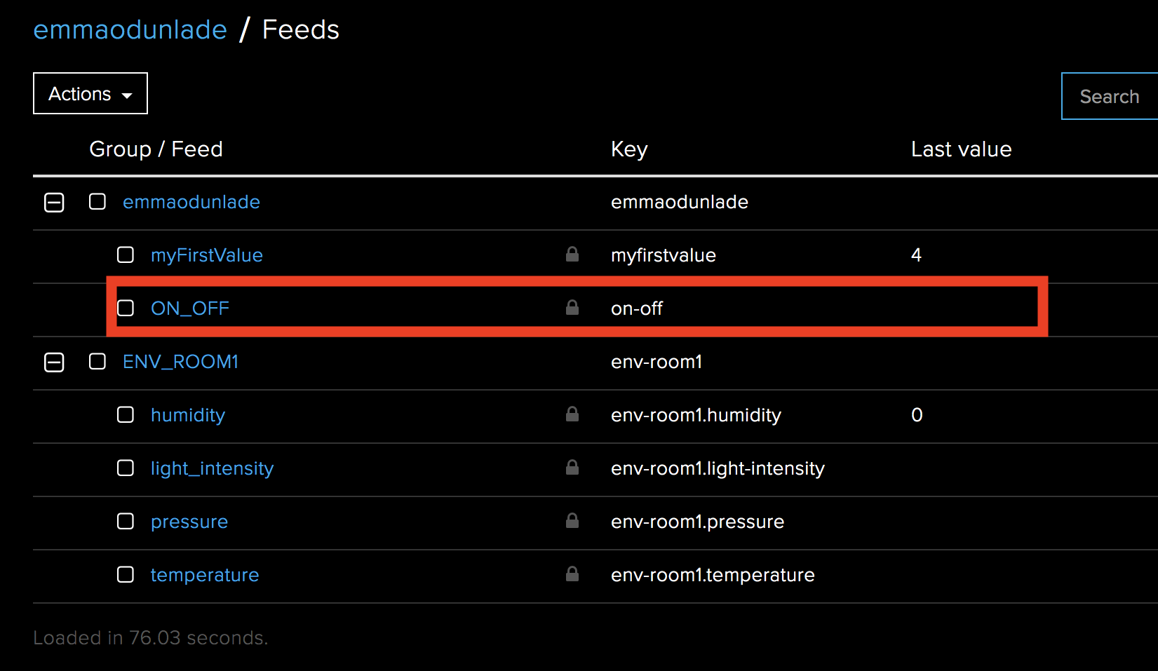
We start by creating a new feed called ON_OFF. This time under the defaults group.
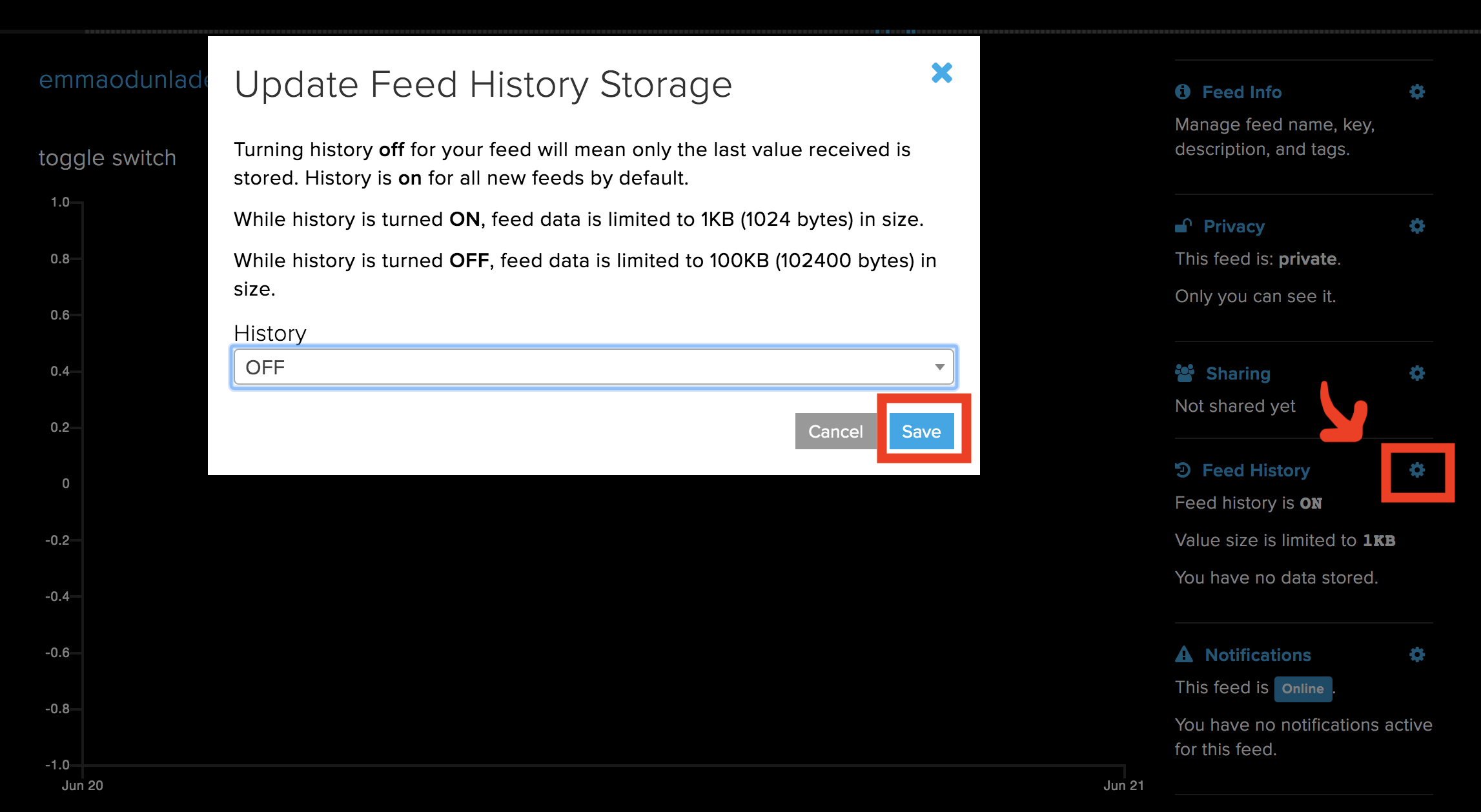
Next, we turn the feed history off so only the current data is available.
Turn off Feed History
It should now be visible with the other feeds as shown below.
ON_OFF Feed Created
Next, we go to the dashboard we created earlier, click the “+” sign and select a toggle switch widget. Fill that dialog box that opens, entering the feed name and other details just like we did for the ones in the first part. You can decide to do this on a new dashboard since we are not focusing on combining both parts of the tutorial.
Dashboard with Toggle Button
With this done, we can proceed to write the code. Just like the first part, in addition to the Adafruit IO REST API (v2.0.0) and the WIFININA library, we will use the MKR RGB Library, the Arduino Json Library and the Arduino Graphics library.
As usual, we start the code by including the libraries that we will use for the project.
Next, we create variables to hold the WiFi credentials. These variables must be entered in the Arduino_Secrets.h file which it is needed to be placed in the same folder as the sketch. We also specify the IO Server and create an object of the WiFi Client Library.
√√char ssid[] = SECRET_SSID; // your network SSID (name)
char pass[] = SECRET_PASS; // your network password (use for WPA, or use as key for WEP)
int status = WL_IDLE_STATUS;
char server[] = "io.adafruit.com"; // name address for Adafruit IOT Cloud
Initialize the client library
WiFiClient client;
Next, we write the void setup function. We start by initializing serial communication, setting the baud rate at 9600. Next we initialize the RGB matrix using the function MATRIX.begin().
With this done, we set the brightness of the display, set the speed at which text scrolls on the display and clear it in preparation for texts to be displayed on it. To wrap up the setup function, the board is connected to wifi using the ConnectToWIFI function.
// set the brightness, supported values are 0 - 255
MATRIX.brightness(200);
// configure the text scroll speed
MATRIX.textScrollSpeed(125);
MATRIX.clear();
MATRIX.endDraw();
ConectToWIFI();
}
Up next is the void loop() function.
Here we start by calling the httpRequest() function to obtain the current state of the toggle switch. If the state is on(1), we clear the RGB display, set the cursor and display “ON” on it, scrolling it left. If the state is off(0), the RGB is cleared, cursor positioned and the “OFF” text is displayed scrolling left. However, if the httpRequest() function returns no valid state due to connectivity issues or any other reason, a blank screen is displayed. The state is displayed on the serial monitor for debugging reasons.
void loop() {
httpRequest();
if (state == 1)
{
MATRIX.clear();
MATRIX.endDraw();
MATRIX.beginText(0, 0, 0, 127, 0); // X, Y, then R, G, B
MATRIX.print(" ON");
MATRIX.endText(SCROLL_LEFT);
}else if (state == 0)
{
MATRIX.clear();
MATRIX.endDraw();
MATRIX.beginText(0, 0, 127, 0, 0); // X, Y, then R, G, B
MATRIX.print(" OFF");
MATRIX.endText(SCROLL_LEFT);
}else
{
MATRIX.clear();
MATRIX.endDraw();
}
Serial.println(state);
}
The complete code for this part is available below and under the download section.
#include <ArduinoJson.h>
#include <ArduinoGraphics.h>
#include <Arduino_MKRRGB.h>
#include <WiFiNINA.h>
#include "arduino_secrets.h"
char ssid[] = SECRET_SSID; // your network SSID (name)
char pass[] = SECRET_PASS; // your network password (use for WPA, or use as key for WEP)
int status = WL_IDLE_STATUS;
char server[] = "io.adafruit.com"; // name address for Adafruit IOT Cloud
///////////////////////////
// Initialize the client library
WiFiClient client;
int state = 2;
void setup() {
Serial.begin(9600);
//while (!Serial); // wait for serial port to connect. Needed for native USB port only
// initialize the display
MATRIX.begin();
// set the brightness, supported values are 0 - 255
  MATRIX.brightness(200);

   // configure the text scroll speed
  MATRIX.textScrollSpeed(125);

  MATRIX.clear();
  MATRIX.endDraw();

  ConectToWIFI();

}
void loop() {

    httpRequest();
    if (state == 1)
    {
      MATRIX.clear();
      MATRIX.endDraw();
      MATRIX.beginText(0, 0, 0, 127, 0); // X, Y, then R, G, B
      MATRIX.print(" ON");
      MATRIX.endText(SCROLL_LEFT);

    }else if (state == 0)
    {
      MATRIX.clear();
      MATRIX.endDraw();
      MATRIX.beginText(0, 0, 127, 0, 0); // X, Y, then R, G, B
      MATRIX.print(" OFF");
      MATRIX.endText(SCROLL_LEFT);
    }else
    {
      MATRIX.clear();
      MATRIX.endDraw();
    }

    Serial.println(state);

}
// this method makes a HTTP connection to the server:
void httpRequest()
{
// JSon
/*
* GET: /api/v2/{username}/feeds/{feed_key}/data/last
{
"id": "string",
"value": "string",
"feed_id": 0,
"group_id": 0,
"expiration": "string",
"lat": 0,
"lon": 0,
"ele": 0,
"completed_at": "string",
"created_at": "string",
"updated_at": "string",
"created_epoch": 0
}
*/
// close any connection before send a new request.
// This will free the socket on the Nina module
client.stop();
Serial.println("\nStarting connection to server...");
if (client.connect(server, 80))
{
Serial.println("connected to server");
// Make a HTTP request:
client.println("GET /api/v2/" IO_USERNAME "/feeds/on-off/data/last HTTP/1.1");
client.println("Host: io.adafruit.com");
client.println("Connection: close");
client.println("Content-Type: application/json");
client.println("X-AIO-Key: " IO_KEY);
// Terminate headers with a blank line
if (client.println() == 0) {
Serial.println(F("Failed to send request"));
return;
}
// Check HTTP status
char status[32] = {0};
client.readBytesUntil('\r', status, sizeof(status));
if (strcmp(status, "HTTP/1.1 200 OK") != 0) {
Serial.print(F("Unexpected response: "));
Serial.println(status);
return;
}
// Skip HTTP headers
char endOfHeaders[] = "\r\n\r\n";
if (!client.find(endOfHeaders)) {
Serial.println(F("Invalid response1"));
return;
}
// Skip Adafruit headers
char endOfHeaders2[] = "\r";
if (!client.find(endOfHeaders2)) {
Serial.println(F("Invalid response2"));
return;
}
//Deserialize JSon
const size_t capacity = JSON_OBJECT_SIZE(12) + 170;
StaticJsonDocument<capacity> doc;
DeserializationError error = deserializeJson(doc, client);
if (error) {
Serial.print(F("deserializeJson() failed: "));
Serial.println(error.c_str());
return;
}
const char* value = doc["value"];
Serial.print("get data!:");
Serial.println(value);
if (strcmp(value, "ON") == 0)
state = 1;
else if (strcmp(value, "OFF") == 0)
state = 0;
else
state = 2;
} else {
// if you couldn't make a connection:
Serial.println("connection failed");
state = 2;
}
}
void ConectToWIFI()
{
// check for the WiFi module:
if (WiFi.status() == WL_NO_MODULE) {
Serial.println("Communication with WiFi module failed!");
// don't continue
while (true);
}
String fv = WiFi.firmwareVersion();
if (fv < "1.0.0") {
Serial.println("Please upgrade the firmware");
}
// attempt to connect to Wifi network:
while (status != WL_CONNECTED) {
Serial.print("Attempting to connect to SSID: ");
Serial.println(ssid);
// Connect to WPA/WPA2 network. Change this line if using open or WEP network:
status = WiFi.begin(ssid, pass);
// wait 10 seconds for connection:
delay(10000);
}
Serial.println("Connected to wifi");
printWifiStatus();
}
void printWifiStatus() {
// print the SSID of the network you're attached to:
Serial.print("SSID: ");
Serial.println(WiFi.SSID());
// print your board's IP address:
IPAddress ip = WiFi.localIP();
Serial.print("IP Address: ");
Serial.println(ip);
// print the received signal strength:
long rssi = WiFi.RSSI();
Serial.print("signal strength (RSSI):");
Serial.print(rssi);
Serial.println(" dBm");
}
Demo
With the sketches all done, is time to test out the code.
Just like we did for both the schematics and programming sections, we will also separate the demo into two parts as I believe you will most likely use the same MKR WiFi 1010 board for both parts.
Part 1 Demo
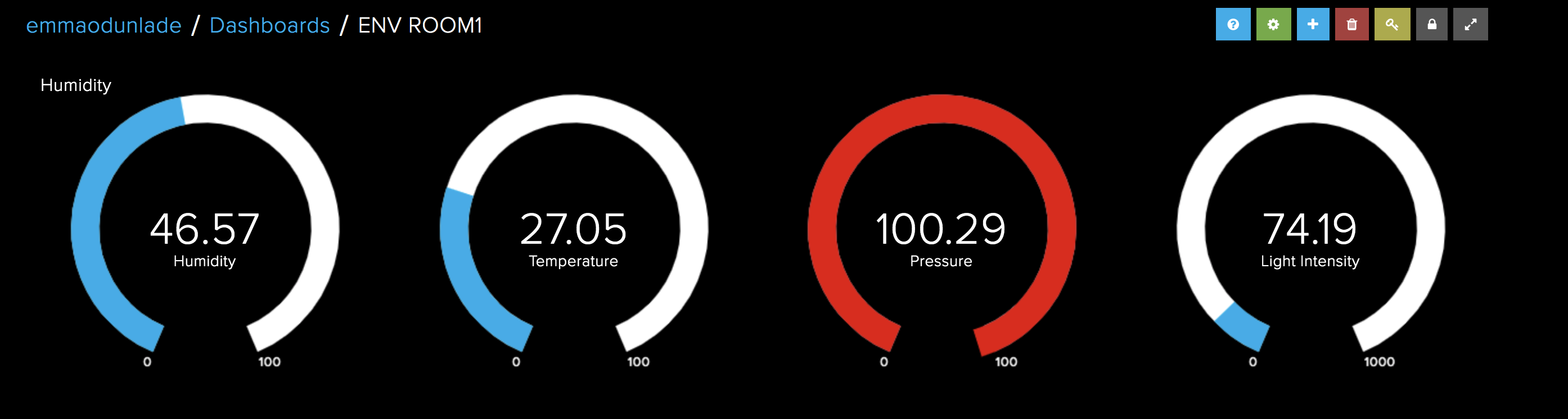
At this stage, we are ready to upload the code to the Arduino MKR WiFi 1010 board. Double check the connections between the Arduino and TFT LCD, and ensure the ENV shield is well plugged in. Also, check to ensure you have filled the credentials for the WiFi access point and your Adafruit IO account in the Arduino_secrets.h file. With this done, upload the code to the Arduino board. After a few minutes, you should see the data live on the Adafruit IO dashboard and the TFT display as shown in the image below.
Demo 1
Part 2 Demo
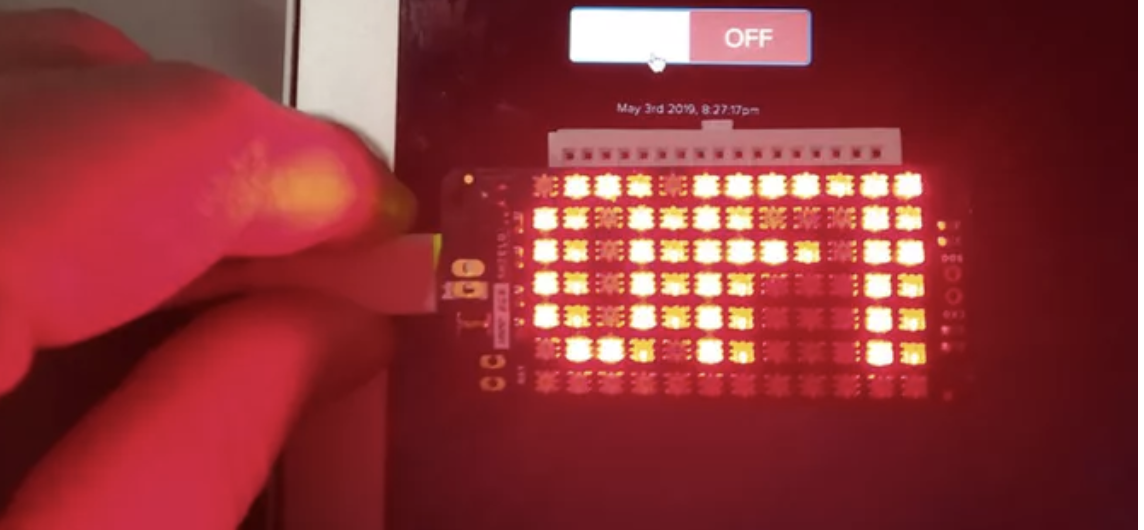
For the Part 2, Plug in the MKR RGB Shield into the MKR WiFi 1010 board as described under the schematics section and double check to ensure you have filled the credentials for the WiFi access point in the Arduino_Secrets.h file.
With everything in place, upload the code to the board and toggle the switch on the dashboard. You should see the text “on”/”off” being displayed on the RGB as you toggle the switch between “on” and “off”.
Demo 2
It is important to note that you can combine both sketches to build a system capable of two way communication with the IoT Cloud. We just separated things so as to be able to explain the steps in details. As a learning challenge, you can try combining the code for both parts or creating a similar project and test it out. That’s it for today’s tutorial, feel free to reach out to me via the comment section with questions and any general comment about today’s project.
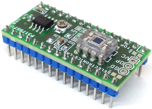
This Arduino Nano Shield consists of a Light sensor, a Magnetic field sensor, and Temperature sensor. The shield can be used to develop various projects required light sensing, magnetic field sensing, and temperature sensing. All sensors provide analog voltage outputs, so each output is connected to analog inputs of Arduino Nano.
Sensors
OPT101 High Sensitive Light Sensor with Adjustable Gain ( Analog Output)
DRV5053 Magnetic Field Sensor ( Analog Output)
LM35 Temperature Sensor ( Analog Output)
Arduino Nano Interface
OPT101 Light sensor output connected to Analog pin of Arduino Nano
Magnetic Field Sensor output connected to Analog pin of Arduino Nano
LM35 Sensor output connected to Analog pin of Arduino Nano
Output
OPT101 provides 7.5mV to 4V ( Minimum Dark Output 7.5V)
DRV5053 Magnetic Field Sensor Output 0-1.8V
LM35 Temperature Sensor Linear + 10-mV/°C Scale Factor
Multi Sensor Shield for Arduino Nano with Light, Magnetic Field & Temperature Sensor – [Link]