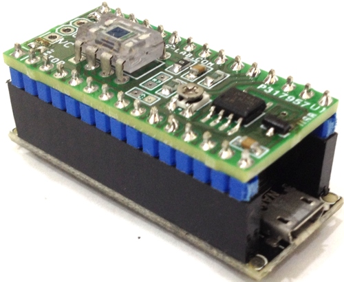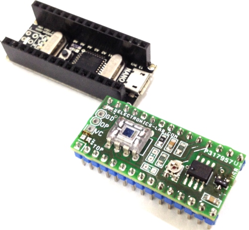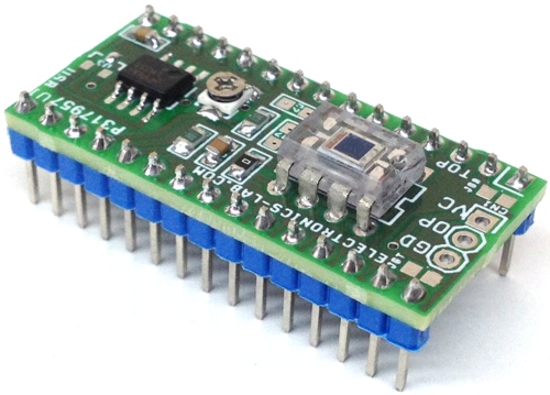
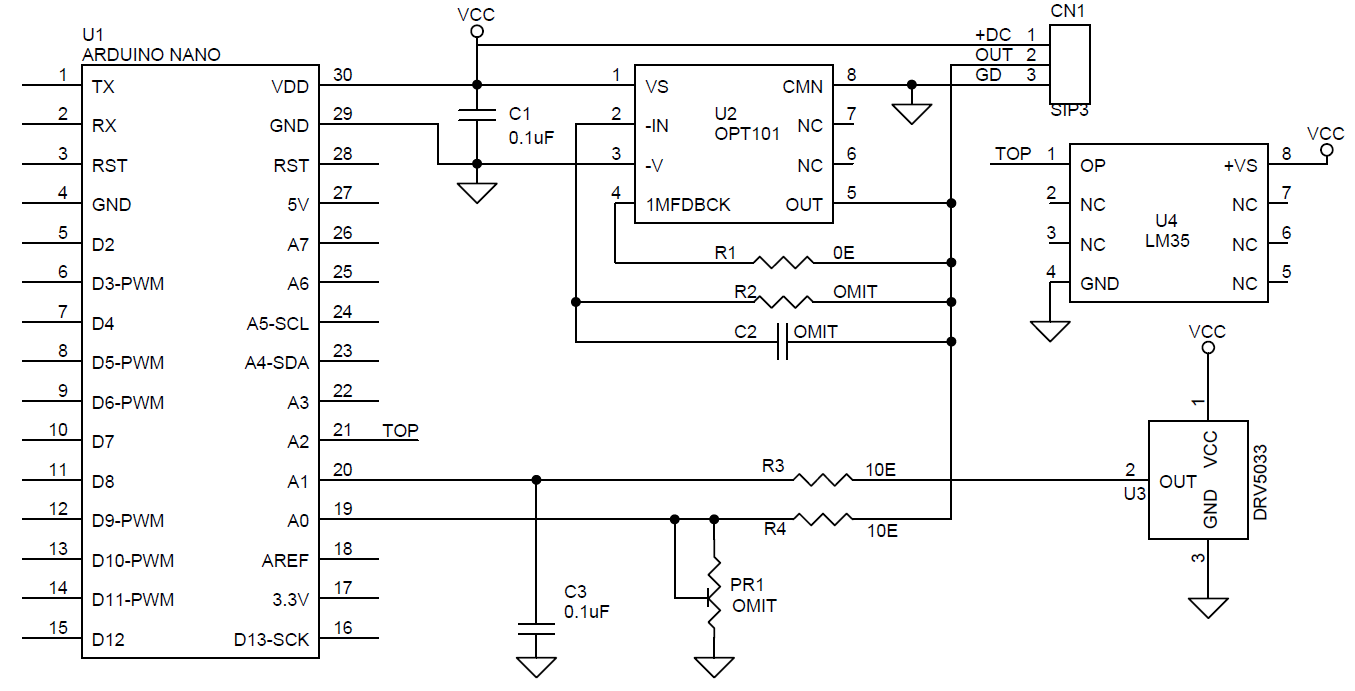
This Arduino Nano Shield consists of a Light sensor, a Magnetic field sensor, and Temperature sensor. The shield can be used to develop various projects required light sensing, magnetic field sensing, and temperature sensing. All sensors provide analog voltage outputs, so each output is connected to analog inputs of Arduino Nano.
Sensors
- OPT101 High Sensitive Light Sensor with Adjustable Gain ( Analog Output)
- DRV5053 Magnetic Field Sensor ( Analog Output)
- LM35 Temperature Sensor ( Analog Output)
Arduino Nano Interface
- OPT101 Light sensor output connected to Analog pin of Arduino Nano
- Magnetic Field Sensor output connected to Analog pin of Arduino Nano
- LM35 Sensor output connected to Analog pin of Arduino Nano
Output
- OPT101 provides 7.5mV to 4V ( Minimum Dark Output 7.5V)
- DRV5053 Magnetic Field Sensor Output 0-1.8V
- LM35 Temperature Sensor Linear + 10-mV/°C Scale Factor
Power Supply: All Sensors connected to 5V of Arduino Nano
OPT101
The OPT101 is a monolithic photodiode with op-chip transimpidance amplifier. The integrated combination of the photodiode and transimpidance amplifier on a single chip eliminates the problems commonly encountered in discrete designs, such as leakage current errors, noise pickup, and gain peaking as result of stray capacitance. Output voltage increases linearly with light intensity. The power amplifier works on single supply. The 2.29mm X 2.29 mm photodiode operates in the photoconductive mode for excellent linearity and low dark current.
The OPT101 is a large-area photodiode integrated with an optimized operational amplifier that makes the OPT101 a small, easy-to-use, light-to-voltage device. The photodiode has a very large measurement area that collects a significant amount of light, and thus allows for high-sensitivity measurements. The photodiode has a wide spectral response with a maximum peak in the infrared spectrum, and a useable range from 300 nm to 1100 nm. from all-analog circuits to data conversion base circuits. The on-chip voltage source keeps the amplifier in a good operating region, even at low light levels. The OPT101 voltage output is the product of the photodiode current times the feedback resistor, (IDRF), plus a pedestal voltage, VB, of approximately 7.5 mV introduced for single-supply operation. Output is 7.5 mV dc with no light, and increases with increasing illumination. Photodiode current, ID, is proportional to the radiant power, or flux, (in watts) falling on the photodiode. At a wavelength of 650 nm (visible red) the photodiode responsively, RI, is approximately 0.45 A/W. Responsively at other wavelengths is shown in Figure 1. The internal feedback
resistor is laser trimmed to 1 MΩ. Using this resistor, the output voltage responsively, RV, is approximately 0.45 V/μW at 650-nm wavelength.
See Figure 2 for the response throughout a wide range of radiant power in microwatts. Figure 3 shows the response throughout a wide range of irradiance in watts per square meter. 8.3.1 Dark Performance the dark errors in the Electrical Characteristics table include all sources. The dominant source of dark output voltage is the pedestal voltage applied to the no inverting input of the op amp. This voltage is introduced to
provide linear operation in the absence of light falling on the photodiode. Photodiode dark current is approximately 2.5 pA, and contributes virtually no offset error at room temperature. The bias current of the op amp summing junction (negative input) is approximately 165 pA. The dark current is subtracted from the amplifier bias current, and these residual current flows through the feedback resistor creating an offset. The effects of temperature on this difference current are seen in Figure 10. The dark output voltage is trimmed to zero with the optional circuit shown in Figure 17. Use a low-impedance offset driver (op amp) to drive pin 8 (Common) because this node has signal-dependent currents.
Responsively To set a different voltage responsively , connect an external resistor, REXT. To increase the responsively, place this resistor in series with the internal 1-MΩ resistor (Figure 18), or replace the internal resistor with an external resistor by not connecting pin 4 (Figure 19). The second configuration also reduces the circuit gain below 106 V/A when using external resistors that are less than 1 MΩ. Shows the basic circuit connections for the OPT101 operating with a single power supply and using the internal 1-MΩ feedback resistor for a response of 0.45 V/μW at 650 nm. Pin 3 (–V) is connected to common in this configuration. Applications with high-impedance power supplies may require decoupling capacitors located close to the device pins as shown.
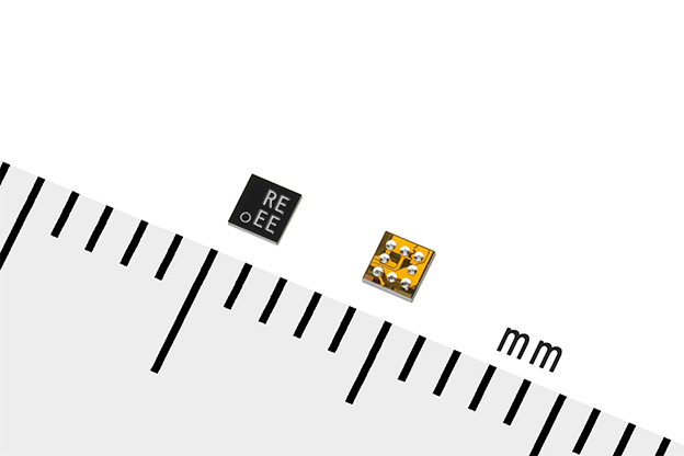
DRV5053
The DRV5053 device is a chopper-stabilized Hall IC that offers a magnetic sensing solution with superior sensitivity stability over temperature and integrates protection features The 0- to 2-V analog output responds linearly to the applied magnetics flux density, and distinguishes the polarity of magnetic field direction. Internal protection functions are provided for reverse supply conditions, load dump, and output short circuit or overcurrent.
The DRV5053 device is a chopper-stabilized Hall sensor with an analog output for magnetic sensing applications. Note that the DRV5053 device will not be operating when approximately –22 to 2.4 V is applied to VCC (with respect to GND). In addition, the device can withstand supply voltages up to 40 V for transient durations. The output voltage is dependent on the magnetic field perpendicular to the package. The absence of a magnetic field will result in OUT = 1 V. A magnetic field will cause the output voltage to change linearly with the magnetic
field. The field polarity is defined as follows: a south pole near the marked side of the package is a positive magnetic field. A north pole near the marked side of the package is a negative magnetic field. For devices with a negative sensitivity (that is, DRV5053RA: –40 mV/mT), a south pole will cause the output voltage to drop below 1 V, and a north pole will cause the output to rise above 1 V. For devices with a positive sensitivity (that is, DRV5053EA: +40 mV/mT), a south pole will cause the output voltage to rise above 1 V, and a north pole will cause the output to drop below 1 V.
LM35
The LM35 series are precision integrated-circuit temperature devices with an output voltage linearly-proportional to the Centigrade temperature. The LM35 device has an advantage over linear temperature sensors calibrated in Kelvin, as the user is not required to subtract a large constant voltage from the output to obtain convenient Centigrade scaling. The LM35 device does not require any external calibration or trimming to provide typical accuracies of ±¼°C at room temperature and ±¾°C over a full −55°C to 150°C temperature range. Lower cost is assured by trimming and calibration at the wafer level. The low-output impedance, linear output and precise inherent calibration of the LM35 device makes interfacing to readout or control circuitry especially easy. The device is used with single power supplies, or with plus and minus supplies. As the LM35 device draws only 60 µA from the supply, it has very low self-heating of less than 0.1°C in still air. The LM35 device is rated to operate over a −55°C to 150°C temperature range, while the LM35C device is rated for a −40°C to 110°C range (−10° with improved accuracy). The LM35-series devices are available packaged in hermetic TO transistor packages, while the LM35C, LM35CA, and LM35D devices are available in the plastic TO-92 transistor package. The LM35D device is available in an 8-lead surface-mount small-outline package and a plastic TO-220 package.
- Calibrated Directly in Celsius (Centigrade)
- Linear + 10-mV/°C Scale Factor
- 5°C Ensured Accuracy (at 25°C)
- Rated for Full −55°C to 150°C Range
- Suitable for Remote Applications
- Low-Cost Due to Wafer-Level Trimming
- Operates from 4 V to 30 V
- Less than 60-µA Current Drain
- Low Self-Heating, 0.08°C in Still Air
- Non-Linearity Only ±¼°C Typical
- Low-Impedance Output, 0.1 Ω for 1-mA Load
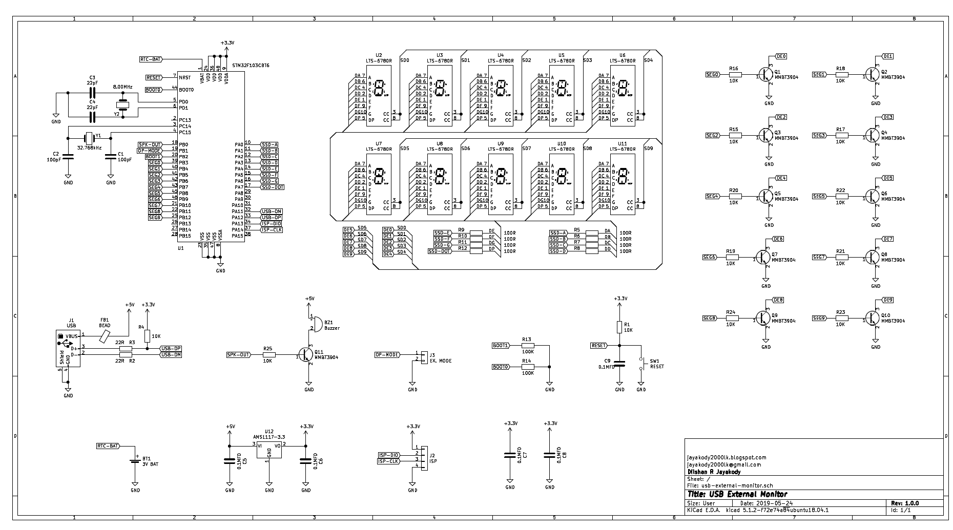
Schematic
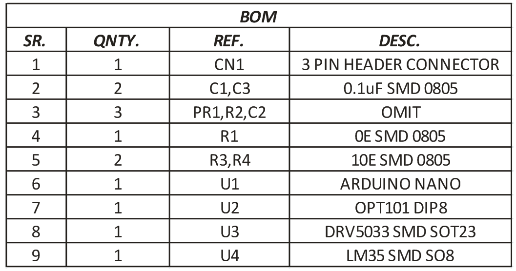
Parts List
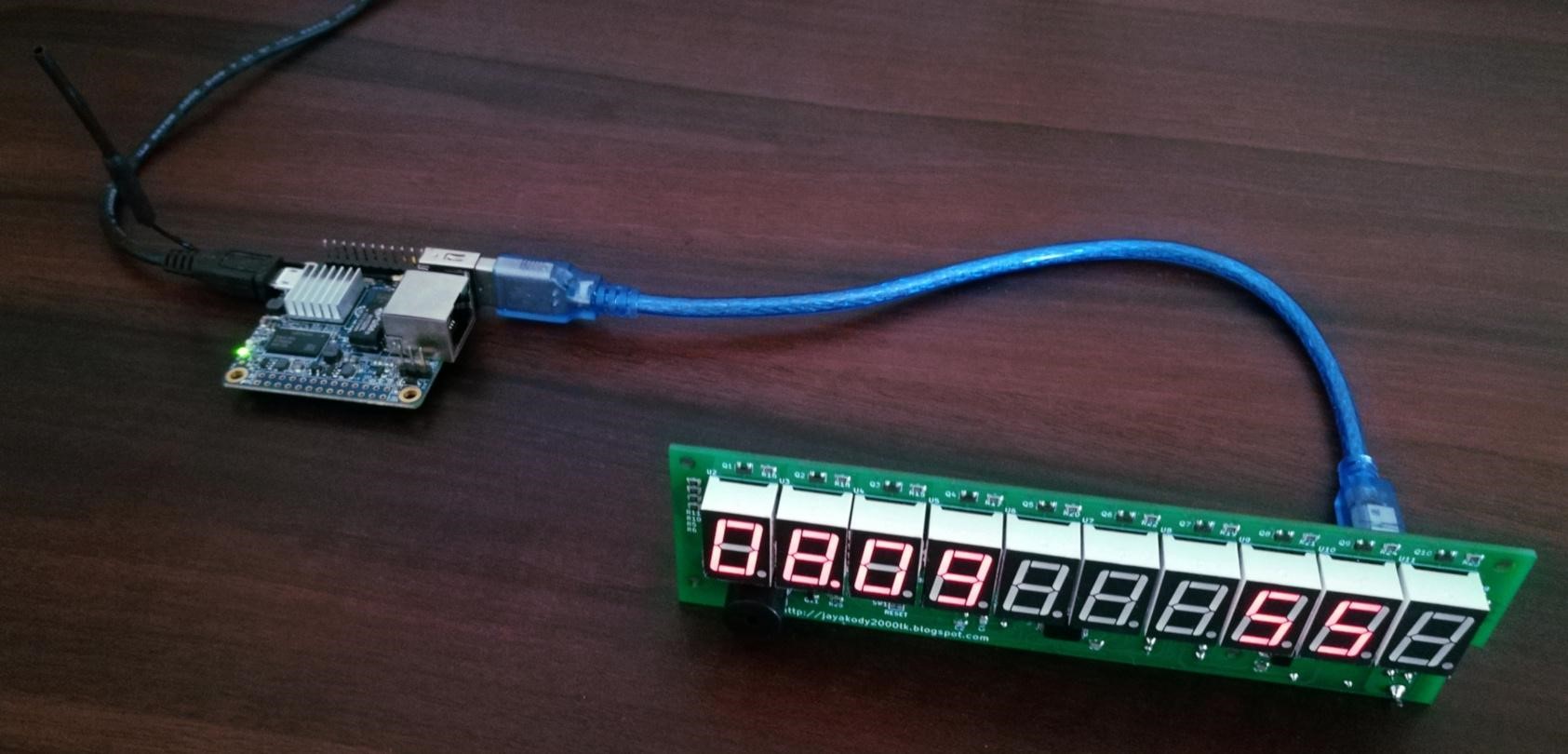
Photos