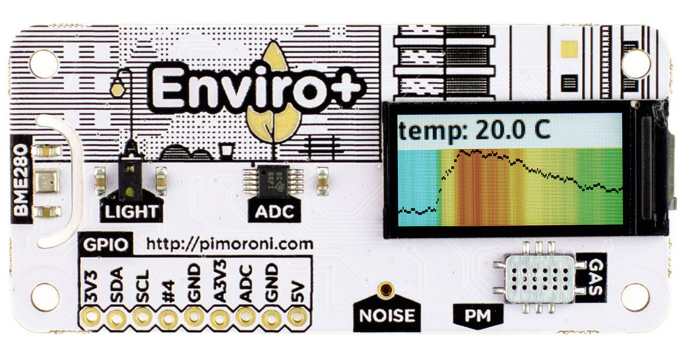
If you reside in an area with high levels of outdoor air pollution, you will probably be breathing more indoor pollutants, which is not good for your health. Of course, that depends on your home’s ventilation system and potential pollution sources. Indoor pollutants range from smoke and carbon monoxide to fumes from carpets, industrial cleaners, and non-stick cooking pans. These pollutants can result in headaches and irritations to long-term respiratory problems and cancer. The good thing is that there are a number of devices that can detect these pollutants, and help us take appropriate actions. Pimoroni has launched a $57 “Enviro+” pHAT for the Raspberry Pi, that can detect indoor air quality, temperature, pressure, humidity, light, and noise. Available also is an optional “PMS5003 Particulate Matter Sensor” you can hook up for detecting outdoor pollution.
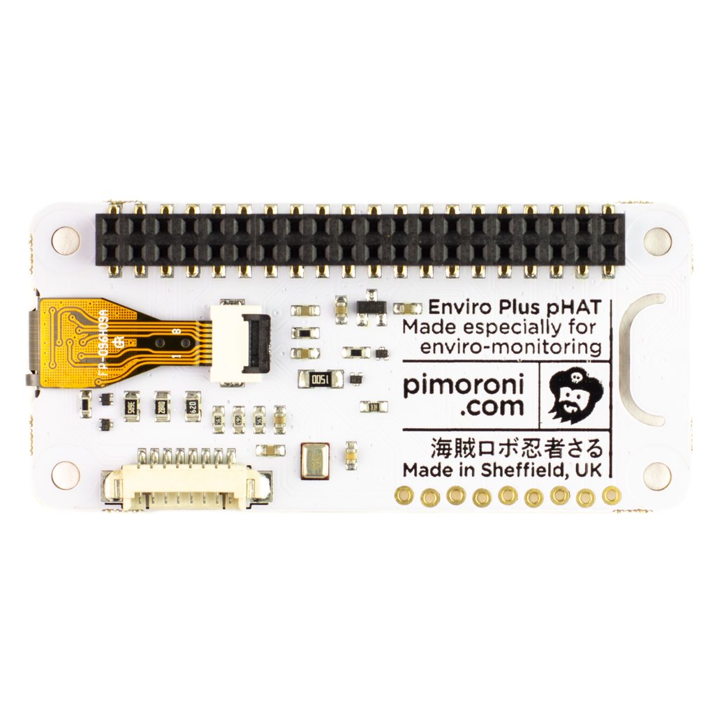
Pimoroni had launched a $20 Enviro pHAT board back in 2016 for the Raspberry Pi. However, its environmental sensors were limited to a temperature/pressure sensor, light sensor, and whatever could be hooked up via the 4-channel analog to digital converter (ADC). The $57 Enviro+ pHAT ditches the accelerometer/magnetometer present in the $20 Enviro pHAT board, and adds humidity and analog gas sensors, with a MEMS microphone for detecting noise levels, and a 1-inch color LCD screen. The Enviro+ has a connector for hooking up the Plantower’s 25-Pound ($32) PMS5003 Particulate Matter Sensor.
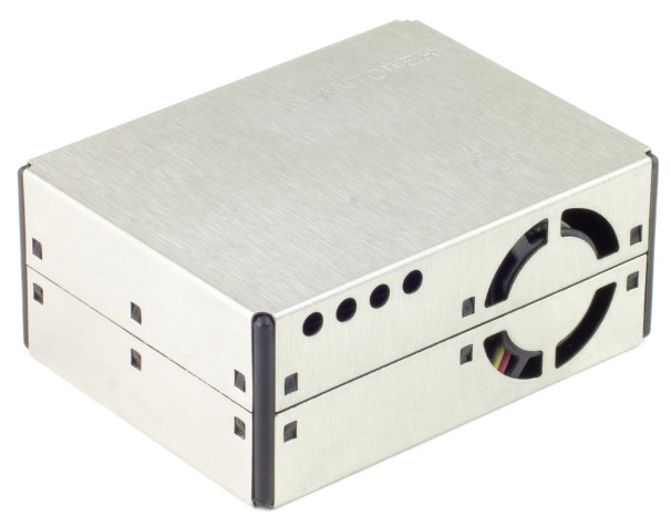
PMS5003
The PMS5003 is designed for detecting outdoor pollution. According to Pimoroni, the gas sensor of the Enviro+ enables qualitative measurements of changes in gas concentrations, “so you can tell broadly if the three groups of gases are increasing or decreasing in abundance.” The company says the reading from the temperature, air pressure, and humidity sensors can not only be used to monitor general indoor conditions but can all affect particulate levels, giving you a more complete picture of air quality.
The Enviro+ is basically designed to control the new PMS5003 Particulate Matter Sensor to monitor real-time external air quality. One of the benefits of the combined platform according to Pimoroni is that it can be used to contribute to open data citizen science projects like Luftdaten. The PMS5003 sensor functions by sensing and discriminating between PM1, PM2.5, and PM10 particulates of various sizes. It is capable of detecting pollutants from sources like smoke, dust, pollen, metal, and organic particles. The device has a small fan that sucks air through the sensor and passes a laser that can detect both the concentration and size of particles. The device comes with a serial port and cable.
Pimoroni suggests the PMS5003 device is designed for indoor use, Plantower however, does not seem to mention this restriction. I feel it can still perform outdoors since most particulate pollutants found indoors emanate from outdoor pollutants. The Enviro+ is available for 45 UK Pounds ($57), the PMS5003 Particulate Matter Sensor is available for 25 Pounds ($32), and 13 Pounds ($16.40) for a pre-soldered Raspberry Pi Zero WH.
Specifications listed for the Enviro+ include:
BME280 temperature, pressure, humidity sensor
LTR-559 ight and proximity sensor
MICS6814 analog gas sensor
ADS1015 ADC with a spare channel for adding another analog sensor
MEMS microphone
0.96-inch, 160 x 80 color LCD
I2C pins for attaching Pimoroni I2C breakouts
Connector for PMS5003 Particulate Matter Sensor
Python libraries, examples, and tutorial on GitHub with IFTTT and Alexa support.
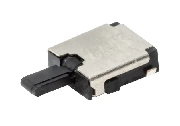
C&K’s FDSD and FDSE series are micro-mini, side-actuated detection switches suitable for applications which require vertical side detection. They are particularly useful for safety control applications, and for medical and consumer devices.
An example of the use of these switches is in inhalers, where they detect the presence of a cartridge, activating the drug delivery process and confirming the dose has been dispensed.
The FDSD and FDSE parts are available now in production volume from Future Electronics. Serving customers from 48 branches in the Europe, Middle East and Africa region, including six branches in Germany, Future Electronics offers the industry’s largest available-to-buy inventory of electronics components – including electro-mechanical components such as the FDSD and FDSE switches.
You can find full pricing and delivery information by clicking here.
The FDSD series of micro-mini side-actuated detection switches are available in a small package size of 4.2mm x 3.6mm x 1.2mm, with optional flat or bent terminals for simple PCB mounting. The beryllium copper contacts have a resistance of less than 1Ω and are rated for 10mA current at 5V DC and a lifetime of 50,000 operations.
The detection switch requires a maximum actuation force of 40gf and can travel through an angle of 60° or a distance of 3.05mm.
Features
Single-pole single-throw configuration
FDSD switches are normally open
FDSE switches are normally closed
100MΩ minimum insulation resistance
100V AC/1 minute dielectric strength
The FDSE range adds an angled capability to the range. Featuring the same package size and lifetime rating, the FDSE switches have an electrical rating of 1mA at 5V DC. The angled detection switch requires a maximum actuation force of 35gf and can travel through an angle of 60° or a distance of 3.14mm.
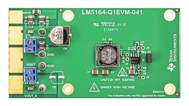
The LM5164 synchronous buck converter is designed to regulate over a wide input voltage range, minimizing the need for external surge suppression components. A minimum controllable on-time of 50 ns facilitates large step-down conversion ratios, enabling the direct step-down from a 48-V nominal input to low-voltage rails for reduced system complexity and solution cost. The LM5164 operates during input voltage dips as low as 6 V, at nearly 100% duty cycle if needed, making it an excellent choice for wide input supply range industrial and high cell count battery pack applications.
Features
Designed for reliable and rugged applications
Wide input voltage range of 6 V to 100 V
Junction temperature range: –40°C to +150°C
Fixed 3-ms internal soft-start timer
Peak and valley current-limit protection
Input UVLO and thermal shutdown protection
Suited for scalable Industrial power supplies and battery packs
Low minimum on- and off-times of 50 ns
Adjustable switching frequency up to 1 MHz
Diode emulation for high light-load efficiency
10.5-µA no-load input quiescent current
3-µA shutdown quiescent current
Optimized for CISPR 32 EMI standard
Integration reduces solution size and cost
COT mode control architecture
Integrated 0.725-Ω NFET buck switch supports wide duty-cycle range
With integrated high-side and low-side power MOSFETs, the LM5164 delivers up to 1-A of output current. A constant on-time (COT) control architecture provides nearly constant switching frequency with excellent load and line transient response. Additional features of the LM5164 include ultra-low IQ and diode emulation mode operation for high light-load efficiency, innovative peak and valley overcurrent protection, integrated VCC bias supply and bootstrap diode, precision enable and input UVLO, and thermal shutdown protection with automatic recovery. An open-drain PGOOD indicator provides sequencing, fault reporting, and output voltage monitoring.
The LM5164 is available in a thermally-enhanced, 8-pin SO PowerPAD™ package. Its 1.27-mm pin pitch provides adequate spacing for high-voltage applications.
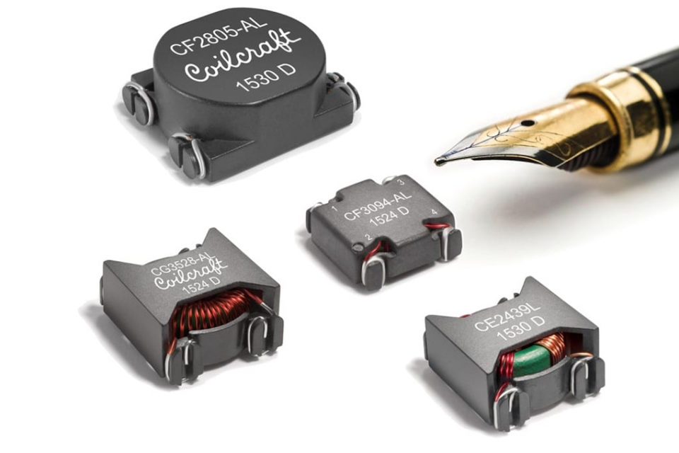
Coilcraft offers the Cx family of surface mount, common mode EMI chokes. There are 16 sizes and configurations to meet the design needs of a broad range of power line circuits, says the company.
They suppress high frequency common mode noise up to 100MHz and offer greater than 40dB common mode attenuation, making them particularly suitable for use in consumer electronics and industrial applications.
All Cx EMI chokes have a low-profile, toroidal construction in a surface-mount, magnetically-shielded package with dimensions as small as 13 x 13mm. They are available with current ratings up to 10A and provide 1,000 or 1,500V rms isolation (hipot) between windings. They feature RoHS-compliant tin-silver-copper over tin over nickel over phosphor bronze terminations and withstand a maximum reflow temperature of 260 degrees C.
Free evaluation samples and complete technical specifications for the Cx Family are available online. Parts are available from stock and can be ordered online from Coilcraft.
Coilcraft is headquartered outside of Chicago in Cary, Illinois, USA. Coilcraft is a leading global supplier of magnetic components including high performance RF chip inductors, power magnetics and filters. It offers a large selection of standard components, and also designs and builds custom magnetics to fit a customer’s exact electrical requirements.
Maker Asia is an organization in South East Asia which owns Maker Lab; a place where makers put their creativity in use. They have recently released a new software product and Maker Asia, who have mostly focused on a hardware product line is eventually into a new space. The newly launched product is an open source IDE; Integrated Development Environment which is suitable for all levels of learning, whether you have just started coding, or the legendary maker, KB-IDE is designed to get you covered.
KB-IDE
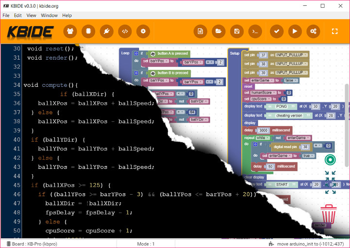
The core of KB-IDE is its dual programming feature which makes it suitable for Beginners and Professionals at the same time. The IDE supports visual programming and can be used as replacement for the Arduino IDE (supports Arduino programming), and even the official Espressif ESP-IDF framework for more experienced makers. KB-IDE is a hackable IDE and sources or modules can be found in the Github repo.
An amazing feature is the framework behind it. It was made with a progressive JavaScript; vue.js. Vue.js is versatile and has core libraries any user needs to work. Users can even separate webpages to different components and work with them individually. Other tools that work with the framework include; code mirror, Blockly, Electron, Webpack, Vuetify and even Kidbright-IDE.
KB-IDE support Both Beginners and Pros alike
KD-IDE has a dual coding style; the block programming style and text programming style. The block programming utilizes Blockly which is quite similar to scratch and beginners will find it easy to use. Not everyone enjoys using the block programming style, so the traditional text programming style is included for the advanced users which use the C/C++ syntax or better still the Arduino programming style. Both styles support converting from block to C/C++ and vice versa as well.
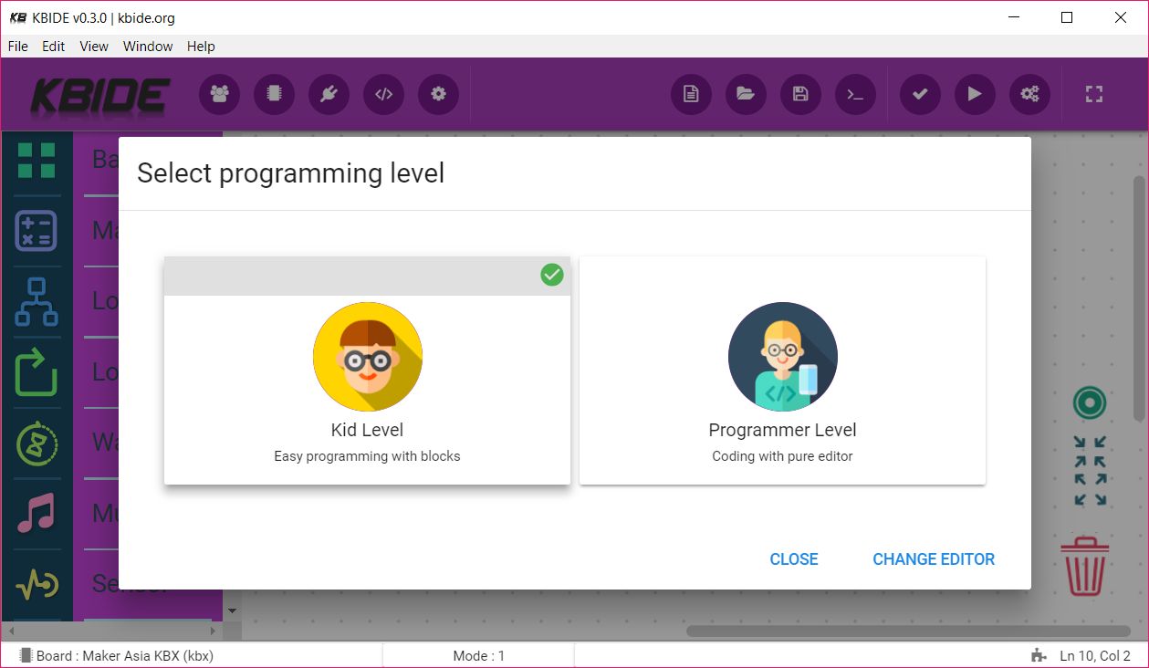
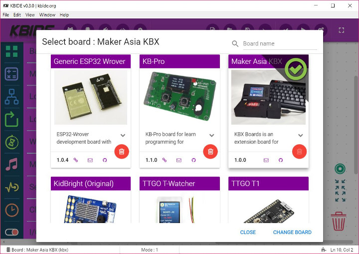
KB-IDE comes with a board manager which helps users switch dev boards quickly, a plug-in system which increases the capacity of the boards and it even works with the Arduino ecosystem. Compared to the Arduino IDE, the KBE-IDE is a 30-60 percent faster when it starts compiling. This is due to its fast compile feature which hopes to solve the issue of slow compiling rate.
KB-IDE Boards Manager feature.
The board manager also shows the names of the different boards thereby making it easier for a user to identify the boards we want to work with. Other features include customizable graphs and controllable sending.
KB-IDE is open source with the code available on Github. You can install a binary release, or build it from source for Windows, Linux, or Mac OS. More information about KB-IDE and Maker Asia is available on their homepage.
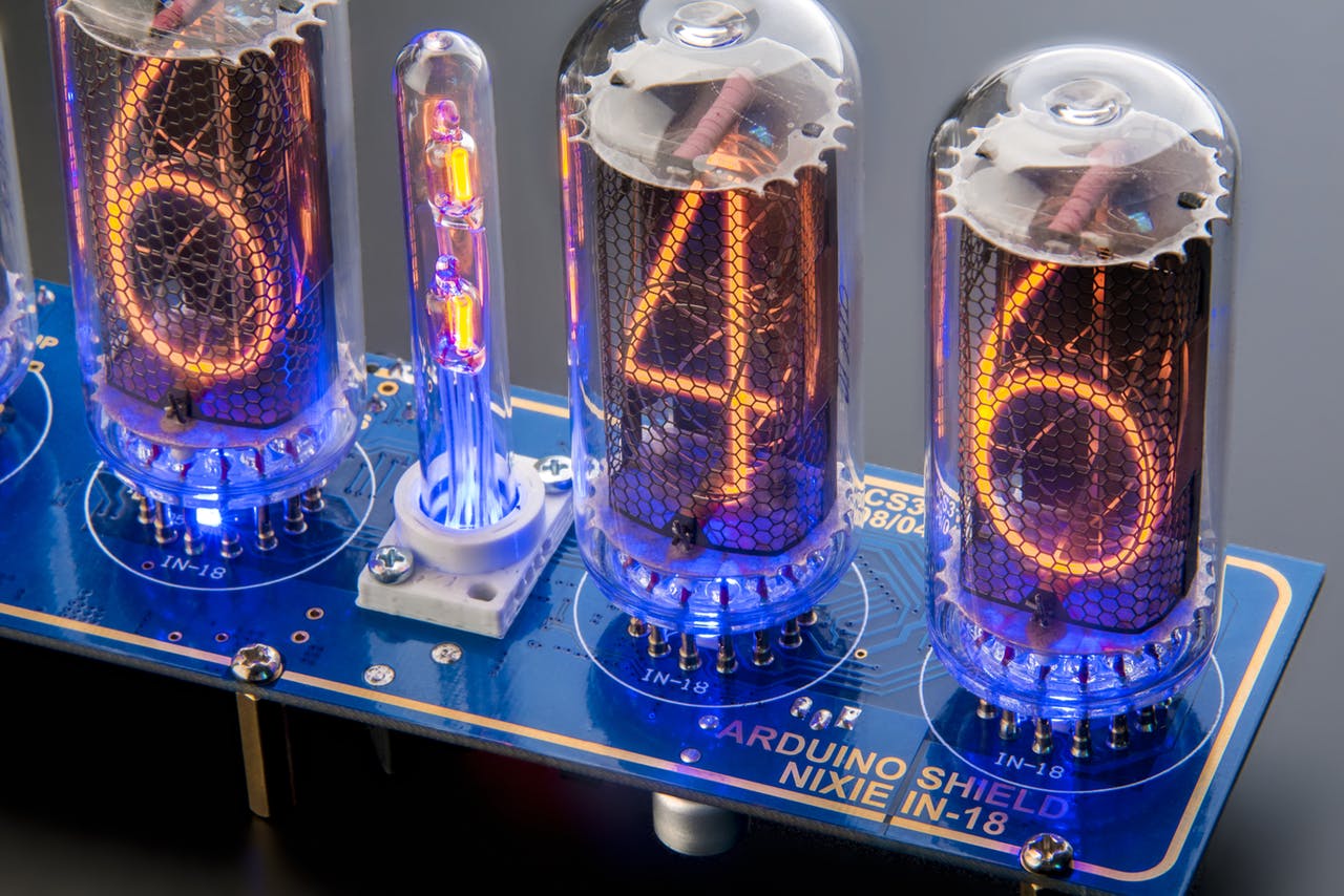
Build your own Nixie tube clock/thermometer/display with ease. by Grisha Anofriev @ www.hackster.io
We set out to create a Nixie clock or just an information indicator on the largest ex-Soviet IN-18 tubes as an Arduino shield-compatible with both Uno and Mega boards.
After a long reading of lots of information about IN-18 tubes on the Internet, we found out that there’s existing issues with so-called “blow glow” and “poisoning” of the tubes.
These two topics discussed considerably on various forums and the main question stands why such effects occurs.
Among possible causes may be: poor supplying voltage, inappropriate supplying current, tubes wearing, switching schemes flaws, unsuitable types of drivers, imperfect control algorithms, untuned types of multiplexing (dynamic or direct – static) and others.
Considering all listed, it was quiet difficult to understand what actually causes the problems of stable usage of these large and beautiful tubes.
Previously we have dealt successfully with the smaller Nixie tubes such as IN-12 and IN-14 and they had no such problems.
Arduino Clock on IN-18 Nixie Tubes with a LONG Service Life – [Link]
We have built quite a number of weather stations in several past tutorials, with each one differing from the other by the use of a different sensor, different display, etc. Today, we are going to build another weather monitoring station using the BME280 Temp and humidity sensor from Adafruit and an OLED display.
The BME280 is an integrated environmental sensor developed specifically for applications where the overall device size and low power consumption are key design constraints. It combines individual high linearity, high accuracy sensors for pressure, humidity and temperature, with an I2C/SPI interface for communication with MCUs. It is designed for low current consumption (3.6 μA @1Hz), long term stability and high EMC robustness.
The humidity sensor embedded in the BME280 features an extremely fast response time to support performance requirements for new applications such as context awareness, and high accuracy over a wide temperature range. The embedded pressure sensor is an absolute barometric pressure sensor with superb accuracy and resolution with very low noise. The integrated temperature sensor was designed to be used for temperature compensation of the pressure and humidity sensors, but can also be used for estimating ambient temperature with high resolution and low noise.
Room Weather Station Using Arduino and BME280 – [Link]
We have built quite a number of weather stations in several past tutorials, with each one differing from the other by the use of a different sensor, different display, etc. Today, we are going to build another weather monitoring station using the BME280 Temp and humidity sensor from Adafruit and an OLED display.
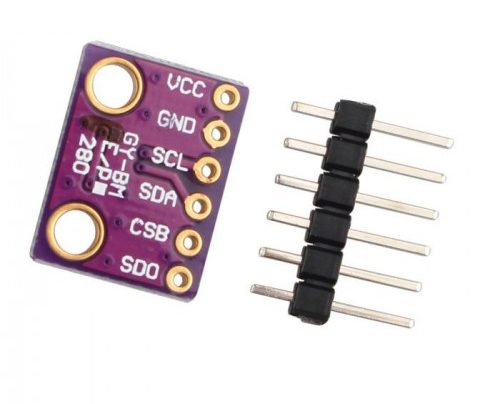
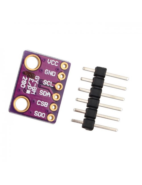
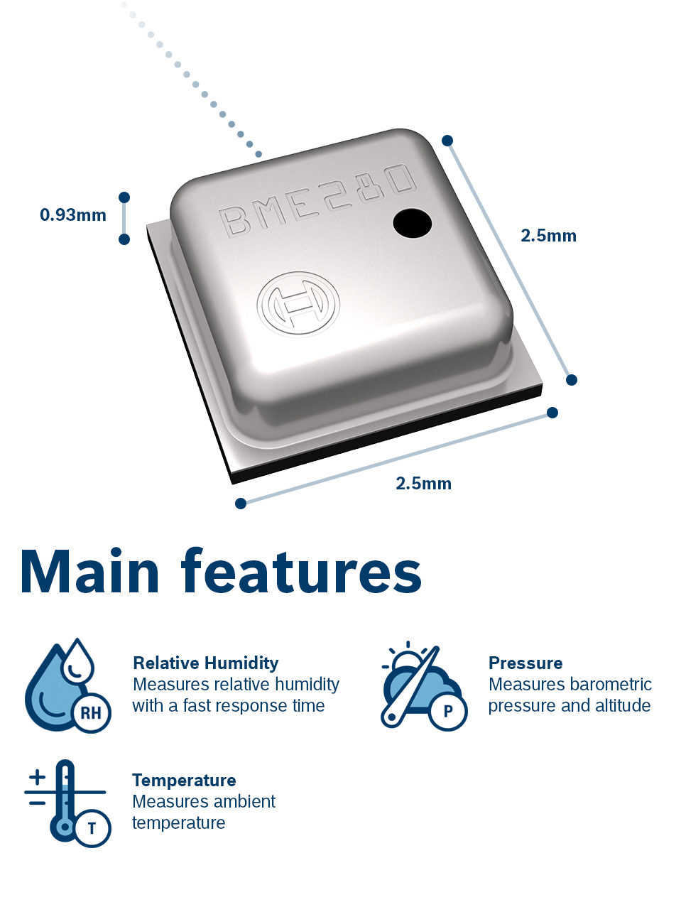
BME280 Temperature, Humidity and Pressure Sensor
The BME280 is an integrated environmental sensor developed specifically for applications where the overall device size and low power consumption are key design constraints. It combines individual high linearity, high accuracy sensors for pressure, humidity and temperature, with an I2C/SPI interface for communication with MCUs. It is designed for low current consumption (3.6 μA @1Hz), long term stability and high EMC robustness.
The humidity sensor embedded in the BME280 features an extremely fast response time to support performance requirements for new applications such as context awareness, and high accuracy over a wide temperature range. The embedded pressure sensor is an absolute barometric pressure sensor with superb accuracy and resolution with very low noise. The integrated temperature sensor was designed to be used for temperature compensation of the pressure and humidity sensors, but can also be used for estimating ambient temperature with high resolution and low noise.
BME280 supports divers operating ranges which makes it flexible and super useful for applications including;
Context awareness, e.g. skin detection, room change detection
Fitness monitoring / well-being
Warning regarding dryness or high temperatures
Measurement of volume and air flow
Home automation control
Control heating, ventilation, air conditioning (HVAC)
Internet of things
GPS enhancement (e.g. time-to-first-fix improvement, dead reckoning, slope detection)
Indoor navigation (change of floor detection, elevator detection)
Outdoor navigation, leisure and sports applications
Weather forecast
Vertical velocity indication (rise/sink speed)
For today’s tutorial however, we will use it to simply obtain temperature, pressure and humidity data to be displayed on adafruit’s 128×64 OLED display. At the end of today’s tutorial, you would know how to use the BME280 and an OLED display with an Arduino Board.
Required Components
The following components are required to build this project;
As usual, the exact version of these components, used for this tutorial can be purchased via the attached links.
Schematics
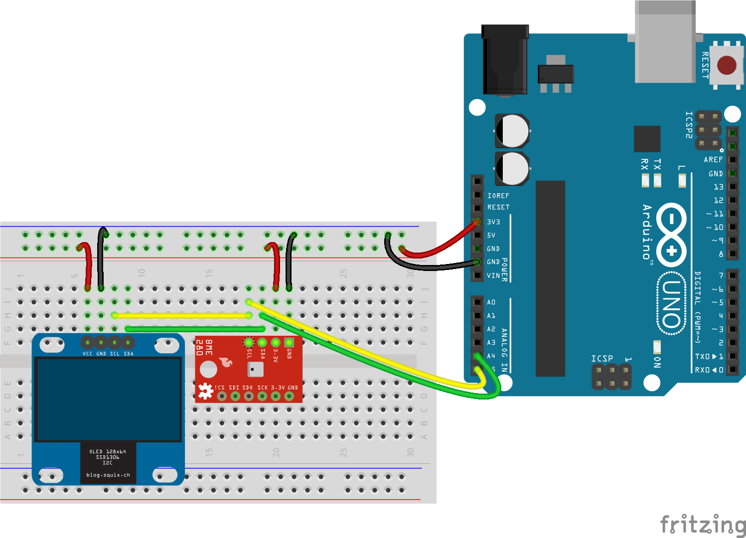
The schematic for today’s project is relatively easy. The BME280 and the OLED display are both I2C based devices, as such, they will be connected to the same pins on the Arduino bus. Connect the components as shown in the schematics below.
Schematics
To show how the devices connect pin to pin, a map is shown below;
OLED – Arduino
SCL - A5
SDA - A4
VCC - 3.3v
GND - GND
BME280 – Arduino
SCL - A5
SDA - A4
VCC - 3.3v
GND - GND
Ensure the connections are properly done before proceeding to the next section.
Code
With the connections done, its now time to program the Arduino. Our goal for today’s project, as described in the introduction, is to simply measure the temperature, humidity, and pressure of the environment and display on the OLED display. To achieve this, we will use three major libraries; the adafruit BME280 library, the Adafruit SH1106 library, and the GFX library. The BME280 library helps to easily interface with the BME280 sensor while the GFX and SH1106 libraries help interface with the OLED display. The libraries can all be installed via the Arduino IDE library manager.
The algorithm for the code is quite simple; Initialize the BME280, obtain readings for each of the parameters and display on the OLED.
To do a breakdown of the code, we start as usual, by including the libraries that will be used. In addition to the three libraries mentioned earlier, we will use a fonts library for better user experience.
With that done, define the OLED_RESET pin, create an instance of the SH11o6 class specifying the OLED_RESET variable as an argument and create an instance of the BME280 class. This will be used to communicate with the BME280 sensor over I2C.
With this done, we then proceed to the setup() function. We start the function by initializing the serial monitor with baudrate at 9600, then initialize the display using the display.begin() function with the I2C address of the OLED display(0x3C) as an argument. This is then followed up with the display.setFont() function to set the font after which the display is cleared.
To wrap up the setup() function, the BME280 is also initialized with the I2C address. the function is initialized such that it stays in a perpetual while loop if the initialization fails.
if (!bme.begin(0x76))
  {
          Serial.println("Could not find a valid BME280 sensor, check wiring!");
          while (1);
        }
}
The I2C address of each of the components, if not written in its datasheet, can be obtained by scanning the I2C line using the method described on the Arduino website.
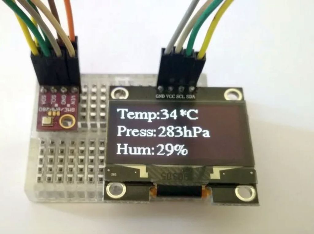
Next, we write the void loop() function. We start by clearing the display using the display.clearDisplay() function after which, for each of the parameters, the value is read using the corresponding function; i.e bme.readTemperature() for temperature, bme.readPressure for pressure, and bme.readHumidity for humidity and displayed on the serial monitor and the OLED display.
Go over the connections once again to ensure you connected everything properly. With that done, copy the code, paste in the Arduino IDE and upload to the Arduino board. You should see the display comes alive as shown in the image below.
Credit: WolfxPac
Works right?
While this is a simple example of what’s is possible with the BME280, by going through the list of applications listed during the introduction, you can begin to imagine the amount of complex problems that can be solved using this sensor.
That’s all for this tutorial guys, thanks for following. Feel free to hit me up via the comment section if you have with all questions you might have about today’s tutorial.
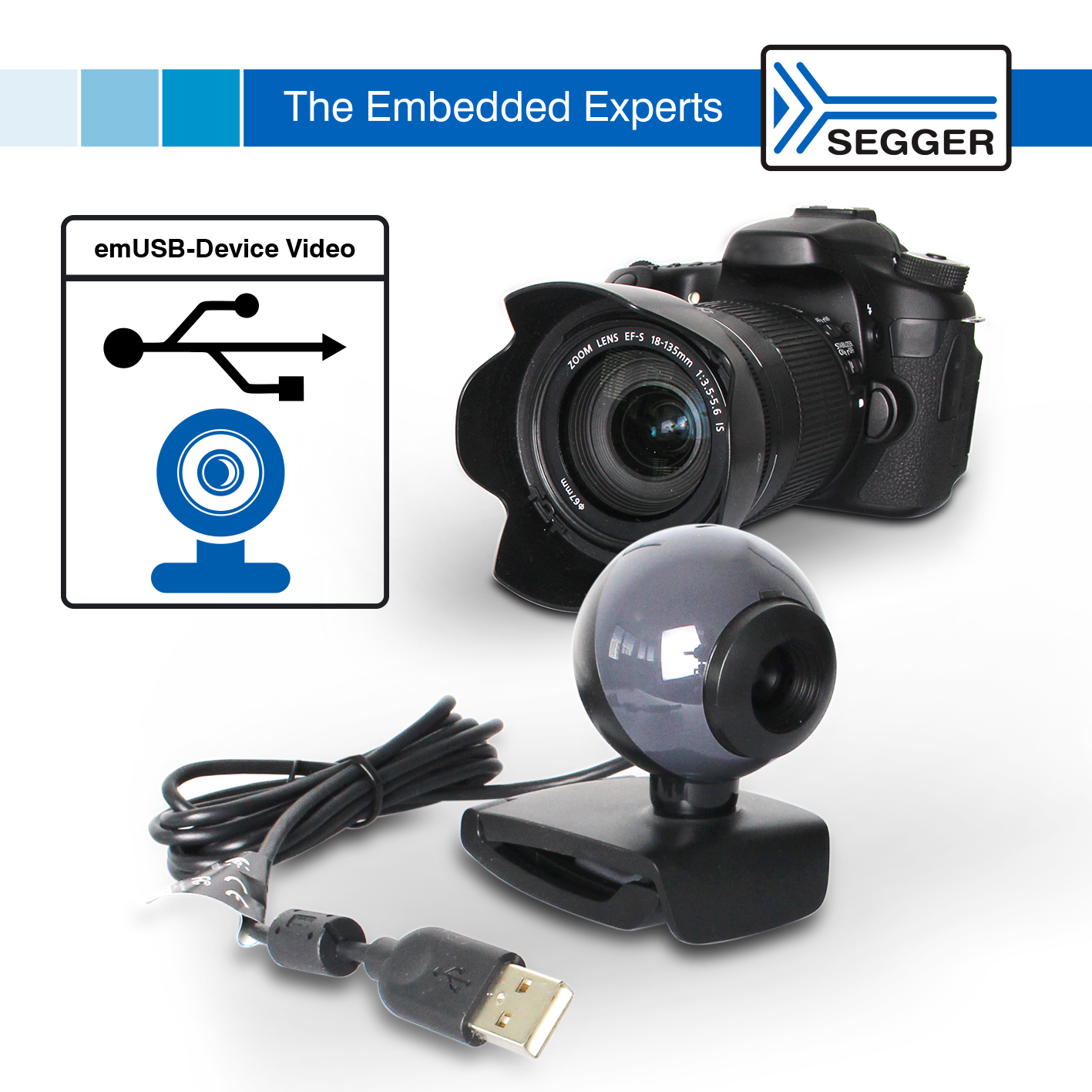
SEGGER introduces video class (UVC) support for emUSB-Device. An Embedded System with a USB device interface can now enumerate as a video camera. Once connected to a Host (Windows, Mac, Linux or Tablet), it is recognized as a camera. Video content can come from a live camera feed, a prerecorded video, or can be generated dynamically by using a graphics library such as SEGGER emWin. The ability to use a host as pluggable display does not cost more than the USB connector. No drivers on the host side are required.
Easily transmit video via USB. Send video data to the host. Simple and driverless! Plug-and-play on any operating system.
USB Video Device class (UVC) V1.1 implementation.
Send video to the host
Cross-platform, no drivers needed on Linux, macOS or Windows
High performance
Small footprint
Typical application examples include digital still cameras, video cameras, webcams, and all other devices that play instructional videos or provide animated video content. It can also be used for “headless” devices, that do not have their own display. There are primarily 2 types of applications: systems which only rarely need a display, such as engines or solar inverters, and systems with separate display units, such as washing machines, where the main processor controls the machine and is connected to a host showing the video on a display.
The video class is a component of SEGGER’s high performance USB stack emUSB-Device. emUSB-Device is specifically designed for Embedded Systems. It runs on any microcontroller and is platform-independent. The flexible device stack enables the creation of multi-class devices using nearly any combination of the available USB classes. emUSB-Device provides classes for Media Transfer Protocol, Mass Storage Device, MSD-CDROM, audio, video, Human Interface Device, CDC-ACM (Serial port communication), IP-over-USB, and printers. It also supports a custom communication interface using bulk transfer for easy and fast communication without protocol overhead. The emUSB-Device is fully compliant with USB standards.
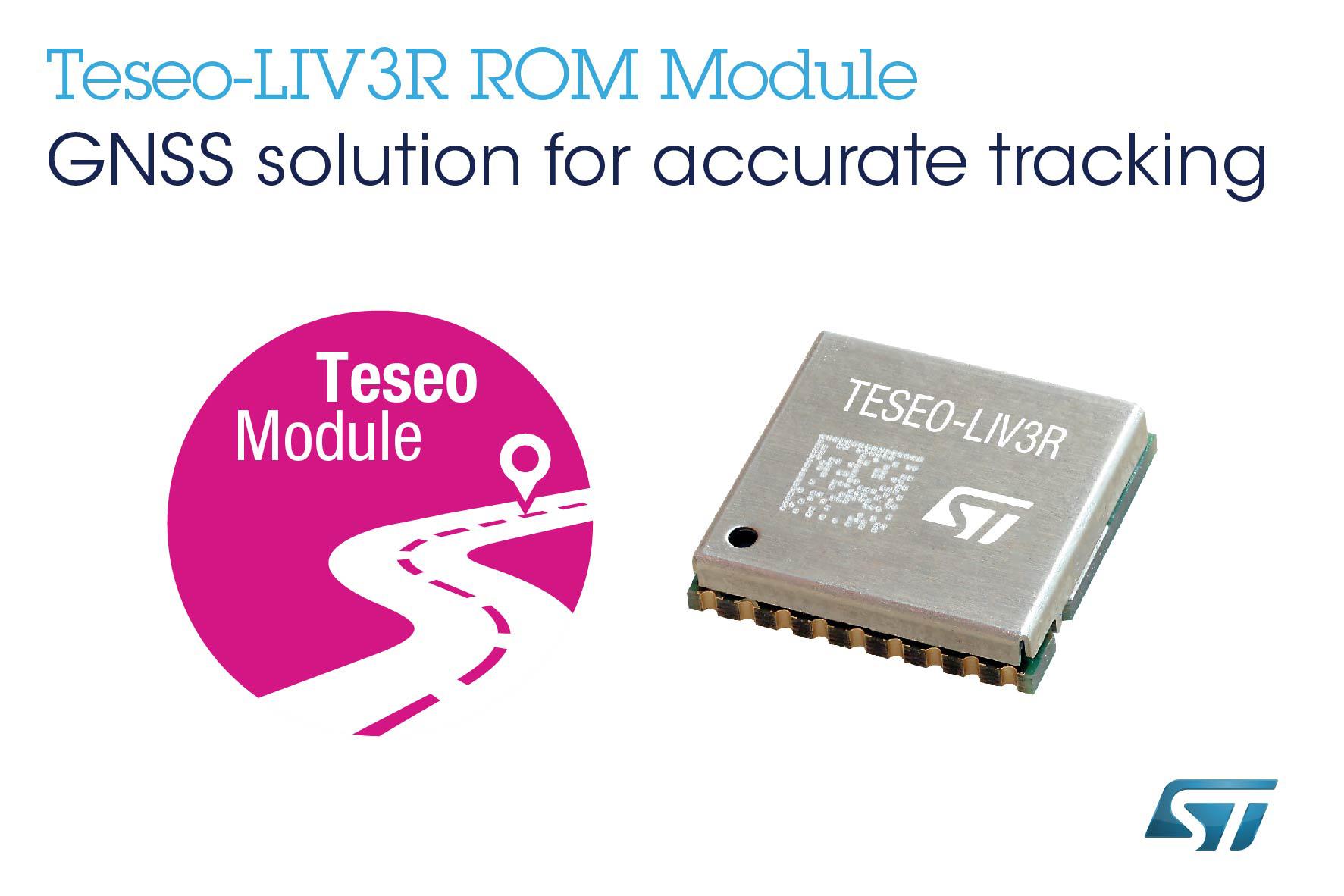
Designed for mass-market tracking and navigation applications, the Teseo-LIV3R ROM-based module, has full GNSS algorithm capability for cost-conscious tracking and navigation devices, says ST Microelectronics.
The GNSS module provides odometer functionality with three trip counters and reached-distance alert, along with geo-fencing capabilities with up to eight configurable circles and crossing-circles alarm. Support for real-time assisted GNSS with free server access ensures uninterrupted positioning data for dependable navigation.
Simultaneous tracking of GPS, Glonass, Beidou, and QZSS constellations, with Satellite-Based Augmentation System (S-BAS) and (Radio Technical Commission for Maritime Services) RTCM V3.1 differential positioning ensures accuracy to within 1.5m (50 per cent Circular Error Probability (CEP). Tracking sensitivity of -163dBm and time-to-first-fix faster than one second ensure high performance for demanding applications. The module responds to proprietary National Marine Electronics Association (NMEA) commands.
Teseo-LIV3R can be used for battery-sensitive applications as it has scalable power consumption according to accuracy, average current, and frequency of fixes, a sub-15µA standby mode with RTC backup, and support for low-power modes, including continuous-fix with adaptive and power-saving cycled modes, periodic-fix with GPS only, and fix-on-demand with the device in permanent standby.
The module is FCC-certified and is supported by the STM32 Open Development Environment. STM32 applications for advanced geolocation, smart tracking, and server-assisted GNSS are available and the EVB-LIV3x evaluation board and X-Nucleo-GNSS1A1 expansion board are also available for hardware development. The Teseo Suite PC tool helps configure settings and fine-tune performance.
The 9.7mm x 10.1mm LCC18 module is in production now. http://www.st.com