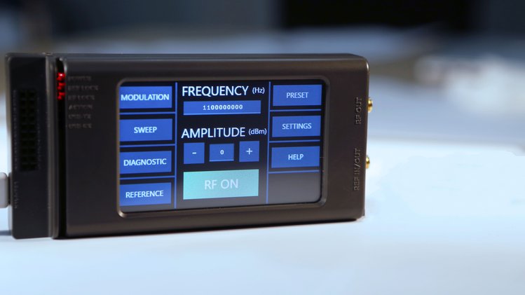
ERASynth Micro is a USB-Powered, Low Priced, Open Source RF Signal Generator, by ERA Instruments.
ERASynth Micro is an open source signal generator with impressive features. Everyone can afford it, including makers, hackers, students, ham radio and SDR users. ERASynth Micro can be powered from a USB port and features an LCD interface for standalone use without a computer or phone. It can generate low phase noise RF signals from 12.5 MHz to 6.4 GHz with a dual PLL architecture.
Open Source: Schematics, embedded Arduino code, LCD screen source code, and RS-232 command set
Makers/Hackers:
RF signal generators are expensive pieces of test equipment mainly used by pro engineers. ERASynth Micro aims remove the cost barrier and make quality RF signal synthesis accessible to everyone, especially the makers.
Students:
ERASynth Micro is for everyone who wants to learn how signal generators work. Since it is open-source and open-schematics, students or anyone who is curious about the inner details of signal synthesis can benefit from ERASynth Micro. You can learn a lot more by reverse engineering and hacking than you can learn in an entire year of a $50k/year engineering school. Learning about the design of test equipment turned Jim Williams into one of the best analog engineers in the world. ERASynth Micro’s advanced design will certainly teach you several RF tricks.
Professionals:
Professional engineers will find ERASynth Micro to be a very good alternative to many of their existing signal generators.
The project is live on CrowdSupply and has 26 days to go. ERASynth Micro Early-bird is for $189.
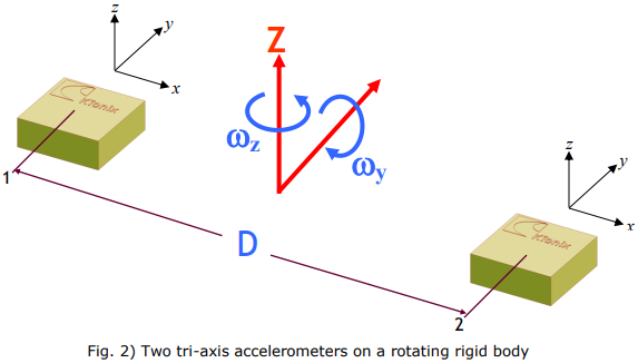
App note from Kionix on utilizing 2 linear accelerometers to determine angular rotational rates.
In many applications, customers would like to measure rotational motions (angular velocity, angular acceleration) in addition to linear motions. Most often, gyroscopes are added to their end product to obtain the rotational information. In some instances, customers already have a system that contains two or more accelerometers. With some understanding of fundamental physics, they can extract more than just linear acceleration data from their system.
Using two tri-axis accelerometers for rotational measurements – [PDF]
The ESP32 has about 4MB of internal flash memory and since the data stored within the flash memory is retained even when power is recycled, it becomes super useful for applications where you need to keep certain amount of data even after power off. For today’s tutorial, we will learn how to read and write data to the ESP32’s Flash Memory.
The flash memory is similar to the EEPROM memory which is common in most microcontrollers. It is a Non-Volatile memory which means that the data stored, remain even when the ESP undergoes a reset or power is cycled. This can be very useful in applications where you need to store particular device settings, remember the last state of a particular variable, or store some important runtime data for later use, etc. To give an example, say a piece of equipment being controlled by the ESP32 was ON when power was cut, in most cases, the equipment will stay OFF when power returns depending on the set parameters but with the help of Flash memory, the system can be programmed to return to the last state that was stored.
As cool as non-volatility is, flash memories, however, have a downside which limits their applications; they usually have a fixed number of write operations. Thus the data in flash memories should only be overwritten when it has been compared and a difference has been established.
To demonstrate the use and capabilities of the flash memory, we will build a dimmer circuit in which a potentiometer is used to vary the brightness of an LED and the system is required to remember the brightness level after a reset. Alongside the use of the Flash memory for storage, at the end of this tutorial, you will know how to use an analog sensor with the ESP32 and how PWM works with it.
Using ESP32’s Flash Memory for data storage – [Link]
The ESP32 has about 4MB of internal flash memory and since the data stored within the flash memory is retained even when power is recycled, it becomes super useful for applications where you need to keep certain amount of data even after power off. For today’s tutorial, we will learn how to read and write data to the ESP32’s Flash Memory.
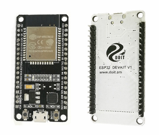
DOIT ESP32 DevKit v1
The flash memory is similar to the EEPROM memory which is common in most microcontrollers. It is a Non-Volatile memory which means that the data stored, remain even when the ESP undergoes a reset or power is cycled. This can be very useful in applications where you need to store particular device settings, remember the last state of a particular variable, or store some important runtime data for later use, etc. To give an example, say a piece of equipment being controlled by the ESP32 was ON when power was cut, in most cases, the equipment will stay OFF when power returns depending on the set parameters but with the help of Flash memory, the system can be programmed to return to the last state that was stored.
As cool as non-volatility is, flash memories, however, have a downside which limits their applications; they usually have a fixed number of write operations. Thus the data in flash memories should only be overwritten when it has been compared and a difference has been established.
To demonstrate the use and capabilities of the flash memory, we will build a dimmer circuit in which a potentiometer is used to vary the brightness of an LED and the system is required to remember the brightness level after a reset. Alongside the use of the Flash memory for storage, at the end of this tutorial, you will know how to use an analog sensor with the ESP32 and how PWM works with it.
Required components
The following components are required for this project;
ESP32 DOIT DEVKIT V1 Board
Breadboard
5mm LED
220 Ohm resistor
10k Potentiometer
Jumper wires
While the project is based on the DOIT’s ESP32 DevKit V1 board, it should also work with any of the other ESP32 based development boards.
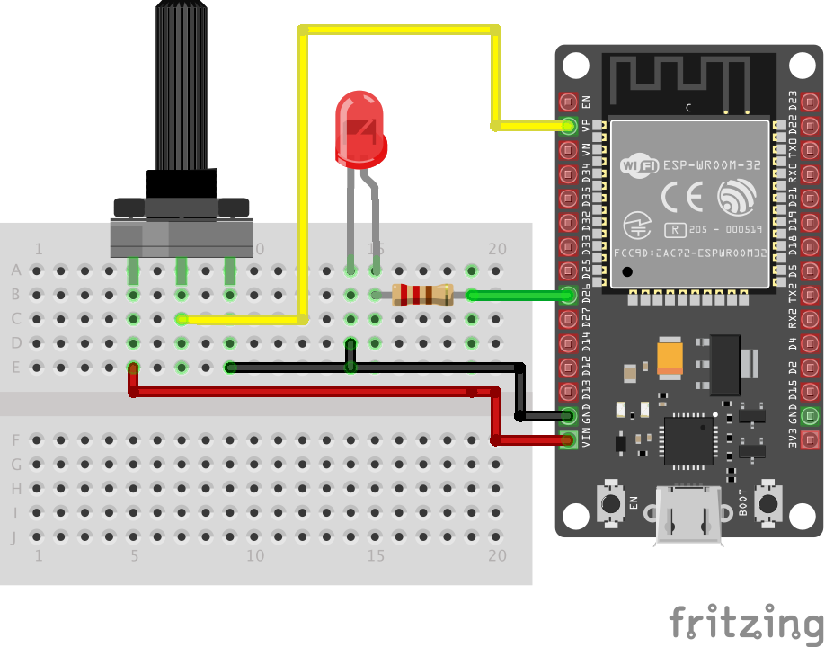
Schematics
Connect the components as shown in the schematics below.
Schematics
Unlike ESP8266, the ESP32 has 18 analog pins to which the potentiometer can be connected, so you can change the pins as desired. Also, all the 36 GPIO pins on the ESP32 board are PWM enabled, so the LED can be connected to any of the GPIO pins.
Code
The code for this project is a little bit tricky. The algorithm performs some simple tasks, such as it simply reads the analog value on the potentiometer, it use it to vary the brightness of the LED and it stores the value in the flash memory, such that the next time the program runs without input from the potentiometer, it uses the last value stored in the flash memory.
As mentioned earlier the Flash memory is a variant of the EEPROM, so it may not be strange that we will use the ESP32 EEPROM library for this project. The library is automatically installed on the Arduino IDE when you install the board files for the ESP32. Its usage is the same as using the Arduino EEPROM library with few differences in function declarations. The EEPROM Library will enable us to use up to 512 bytes of the flash memory. This means we will have 512 different addresses and we will be able to save data between 0 and 255 in each of the addresses. There are three main functions from the EEPROM library associated with storage and retrieval of data;
EEPROM.write(address, value)
EEPROM.commit()
EEPROM.read(address)
To write data to a memory address, the EEPROM.write() function is called with the data and the address to which it should be written supplied as arguments. To complete the data write, the EEPROM.commit() function should be called. The commit function checks to confirm that the data indicated in the write() function is different from what is currently there before committing it to the flash memory. With the finite nature of the number of times data can be written to the Flash memory, the commit() function helps to reduce unnecessary write operations to keep the number of write operations low.
The read() function, on the other hand, is used to retrieve information from the address that is specified as the argument for the function. These three functions will be at the center of today’s project.
We start as usual, by including the libraries required for the code, which in this case is just the EEPROM library.
// include library to read and write from flash memory
#include <EEPROM.h>
Next, we specify the pins of the ESP32 to which the other components are connected and we declare the variables that will be used to store data in the code. One of the downsides of the ESP32 is that the support level is not yet as high as its available for other boards. To write values to a PWM pin on an arduino board, one need just to call the analogWrite() function but this function is not available for the ESP32, thus the variables; freq, ledchannel and resolution will be used to achieve the same tasks as the analogWrite() function.
//GPIO pin declarations
#define ANALOG_PIN_0 36
#define LED_PIN 26

// PMW Parameters
int freq = 5000;
int ledChannel = 0;
int resolution = 8;
int dutyCycle;


// Variables to store the potentiometer;s value and the current state of the LED
int analog_value;
int ledState = 0;         // the current state of the output pin we start with 0
Next, we write the void setup() function. We start the function by initializing serial communication and communications with the EEPROM.
Next, we use the ledcSetup() function to setup the properties of the PWM channel with the resolution, frequency and channel(ledChannel) as arguments, after which we attach the pin to which the LED is connected to the configured PWM channel. The ADC on the ESP32 has a resolution of 10bits and by setting the resolution of the PWM channel to 8bits, we make its values similar to that of the Arduino.
To wrap up the voidsetup() function, we read the EEPPROM to check if there was a previous value for the brightness of the LED and using the EEPROM.read() function and use the ledcWrite() (which is our equivalent of the analogWrite() function) to set the brightness of the LED.
// read the last LED state from flash memory
ledState = EEPROM.read(0);
ledcWrite(ledChannel, ledState);
Next, we write the void loop() function. The function simply checks the input value from the potentiometer, compares it with the last value stored and if there is a difference, the brightness of the LED is set to the new value and the flash memory is updated using the EEPROM commands.
We start the loop() function by reading the analog value from the potentiometer.
analog_value = analogRead(ANALOG_PIN_0);
Since the ADC is by default, at 10bits, we map the value to that of 8bits to ensure it tallies with the PWM resolution we declared earlier.
dutyCycle = map(analog_value, 0, 4095, 0, 255);
Next, we check if there is a difference between the last value and the current one and if there is, we set the brightness of the LED to this new value and update the flash memory with the EEPROM.write() command followed by the commit function.
Serial.println("value changed");
ledcWrite(ledChannel, dutyCycle);
ledState = dutyCycle;
// save the brightness value in flash memory
EEPROM.write(0, ledState);
EEPROM.commit();
Serial.println("New value saved in flash memory");
The complete code is available below and also attached under the download section of the tutorial.
// include library to read and write from flash memory
#include <EEPROM.h>
// define the number of bytes you want to access
#define EEPROM_SIZE 1
//GPIO pin declarations
#define ANALOG_PIN_0 36
#define LED_PIN 26
// PMW Parameters
int freq = 5000;
int ledChannel = 0;
int resolution = 8;
int dutyCycle;
int analog_value;
int ledState = 0;
void setup() {
  Serial.begin(115200);
  // initialize EEPROM with predefined size
  EEPROM.begin(EEPROM_SIZE);
ledcSetup(ledChannel, freq, resolution);
ledcAttachPin(LED_PIN, ledChannel);
// read the last brightness level from flash memory
ledState = EEPROM.read(0);
ledcWrite(ledChannel, ledState);
}
void loop() {
// read the potvalue into a local variable:
analog_value = analogRead(ANALOG_PIN_0);
dutyCycle = map(analog_value, 0, 4095, 0, 255);
if (dutyCycle != ledState)
{
Serial.println("value changed");
ledcWrite(ledChannel, dutyCycle);
ledState = dutyCycle;
// save the brightness level in flash memory
EEPROM.write(0, ledState);
EEPROM.commit();
Serial.println("level saved in flash memory");
}
}
Demo
Ensure the components are connected as described under the schematics section and if you made any changes in pin configurations, ensure the code is updated to reflect them. With this done, connect your DOIT ESP32 DevKit to your PC and upload the code. You should see the brightness of the LED vary as you turn the knob of the potentiometer. Set the Potentiometer to a particular recognizable brightness level, then unplug the system. The device will retain the last saved value and set the brightness of the LED to that value once power is connected again.
While this is a simple example, this can be used for more useful tasks in a more complex project with the same exact commands.
That’s it for today’s tutorial. Feel free to reach me via the comment section if you have any questions or need any clarification as regards this tutorial.
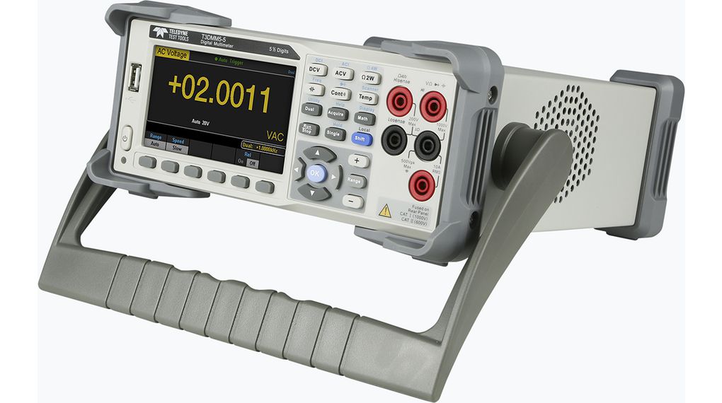
Teledyne Test Tools new T3DMM series are dual display digital desktop multimeters that provide a rich and powerful feature set. The design is easy-to-use from the front-panel and computer-based control via USB or LAN. Each model is equipped with a 4.3 inch TFT-LCD true color screen with 480 * 272 resolution for easy viewing. The T3DMM series also features numerical data display, histograms, trend charts, bar charts and statistics, in addition to the built-in arithmetic functions including Measurement statistics.
Key Features
Available in 4.5 digit (60,000 count), 5.5 digit (240,000 count) and 6.5 digit (2,200,000 count) models.
An additional 6.5 digit model is offered with an integrated Scanner card.
Math functions include: Max, Min, Average, Standard Deviation, dBm/dB, Relative Measurement, Pass/Fail Histogram, Trend Chart, Bar Meter etc.
True RMS AC Voltage and Current Measurements.
Support for remote control operation.
Main Features and Functions of the T3DMM4-5
Real 4½ digit (60,000 counts) readings resolution
Up to 150 rdgs/s measurement speed
True-RMS AC Voltage and AC Current measuring
1 Gb NAND flash size, Mass storage configuration files and data files
Built-in cold terminal compensation for thermocouple
Standard interface: USB Device, USB Host, LAN
DC Voltage: 600 mV ~ 1000 V
DC Current: 600 μA ~ 10 A
AC Voltage: True-RMS, 600 mV ~ 750 V
AC Current: True-RMS,60 mA ~ 10 A
2/4-Wire Resistance: 600 Ω ~ 100 MΩ
Capacitance: 2 nF ~ 10000 μF
Continuity Test: Rang e is fixed at 2 kΩ
Diode Test: Adjustable range is 0~4 V.
Period Measurement: 2 μs ~ 0.05 s
Temperature: Support for TC and RTD sensor
Max, Min, Average, Standard Deviation, dBm/dB, Relative Measurement, Pass/Fail
The digital multimeter series is available for purchase from various distributors online starting from ~$613.
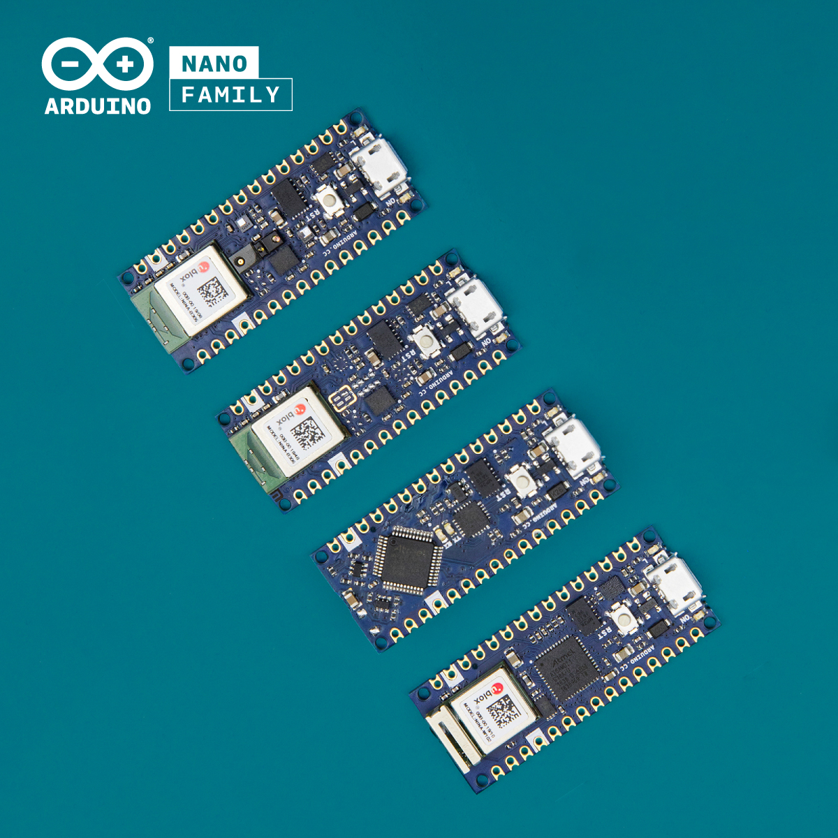
Arduino has begun pre-orders for four new 45 x 18mm Nano form-factor boards. They include a $10 “Arduino Nano Every” model, a faster “WiFi/BT-enabled IoT” model, and two BLE boards. The Arduino Nano Every Substitutes the ATmega328P-based Arduino Uno-like Nano 3, equipped with ATMega4809, which is more powerful, and energy-efficient, and previously present in Arduino boards like the Arduino Uno WiFi Rev 2. The Nano Every features a 25 percent higher clock speed, 50 percent more flash, and 3x times the SRAM of the Nano 3.
The Nano Every integrates the USB-to-serial chip, which enables advanced users with some additional hacking options. Hackaday, reports that the board “turns up with 21V input into the 5V regulator, with the added advantage of sourcing up to 1 A for external components through the 5 V pin on one of the headers.” This enables a hacker to “choose to inject their unregulated power through the Vin line, or the USB header.” The three 32-bit Nano 33 boards all run at 3.3V. The $18 to $20 Nano 33 IoT enables the SAMA21 MCU and ESP32-based U-blox NINA-W102 WiFi (802.11b/g/n) and Bluetooth 4.2 module.
The Nano 33 IoT enables Arduino IoT Cloud, and also a full TLS secure transport via the crypto chip. The IMU further expands potential mobile and robotics applications. The Nano 33 BLE, and Nano 33 BLE Sense feature a U-blox NINA B306 module based on Nordic Semi’s Bluetooth 5.0 fitted nRF52480 processor. The boards are majorly built for wearables and other low-power devices that require short-range BLE communications. Both models enable a 9-axis IMU. The BLE Sense board incorporates temperature, pressure, humidity, light, color, and gesture sensors features. The BLE Sense also includes a microphone and the ATECC608A crypto chip found on the Nano 33 IoT.
The four Nano boards are listed with pricing (with or without headers):
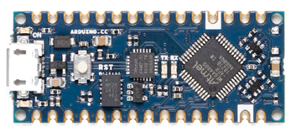
Arduino Nano Every
Arduino Nano Every goes for $9.90 or $11.90, with a 20MHz Microchip ATMega4809 AVR with 48KB flash, 6KB SRAM; USB-to-serial via Microchip SAMD11D14A (Cortex-M0+)
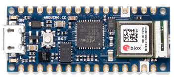
Arduino Nano 33 IoT
Arduino Nano 33 IoT goes for $18 or $20, with 48MHz SAMD21G18A (32-bit Cortex-M0+), 256KB flash, 32KB SRAM, U-blox NINA W102 (ESP32) WiFi/BT module, Microchip ATECC608A crypto chip and 6-axis IMU.
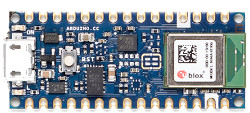
Arduino Nano 33 BLE
Arduino Nano 33 BLE goes for $19 or $21 with 64MHz U-blox NINA B306 (Nordic Semi nRF52840 based on Cortex-M4F), Bluetooth 5.0 LE, 256KB flash, 1MB SRAM and 9-axis IMU.
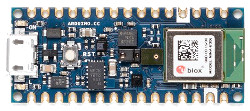
Arduino Nano 33 BLE Sense
Arduino Nano 33 BLE Sense goes for$29.50 or $31.50 with 64MHz U-blox NINA B306 (Nordic Semi nRF52840 based on Cortex-M4F), Bluetooth 5.0 LE, 256KB flash, 1MB SRAM, ATECC608A crypto chip, 9-axis IMU, multiple sensors and mic.
Shipments will begin in mid-June for the Arduino Nano Every, and also the higher-end, WiFi-enabled Nano 33 IoT. The shipping date is slated for mid-July for the Bluetooth-equipped Nano 33 BLE and Nano 33 BLE Sense wearable modules.
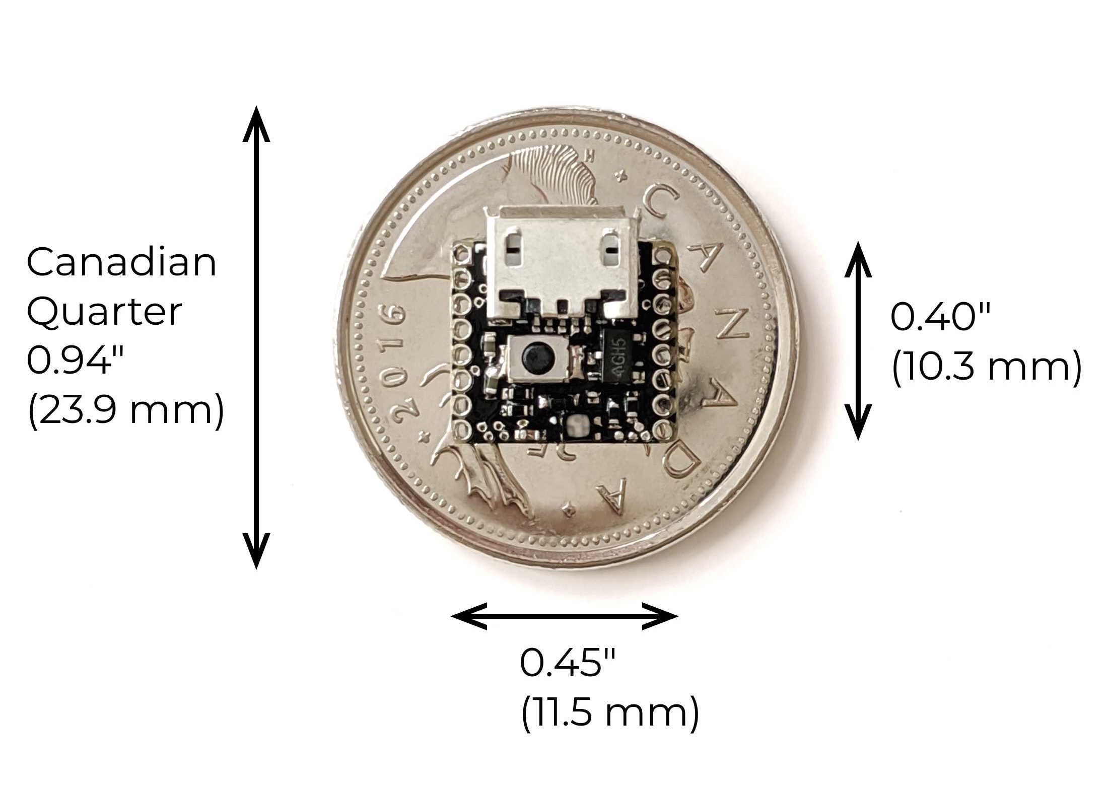
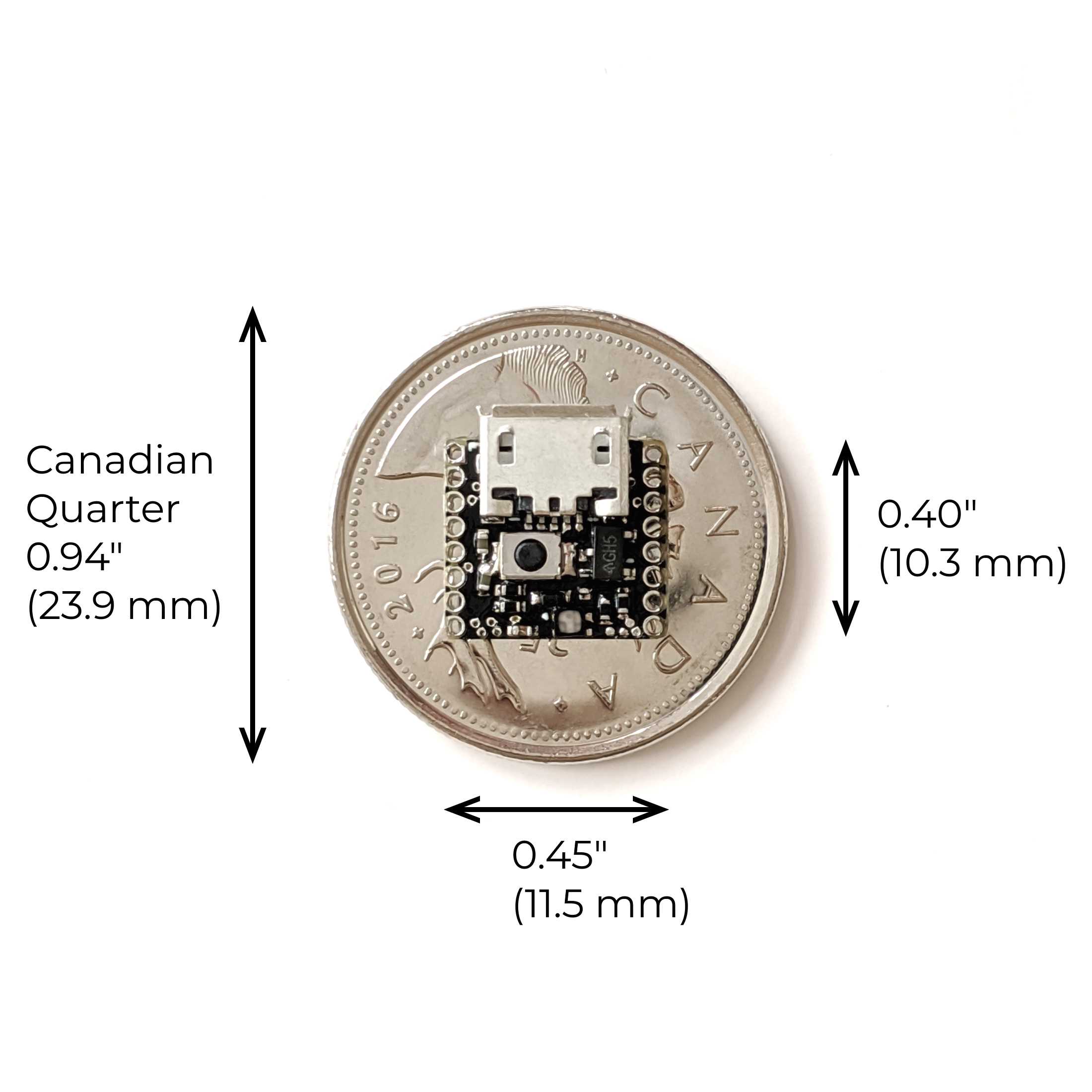
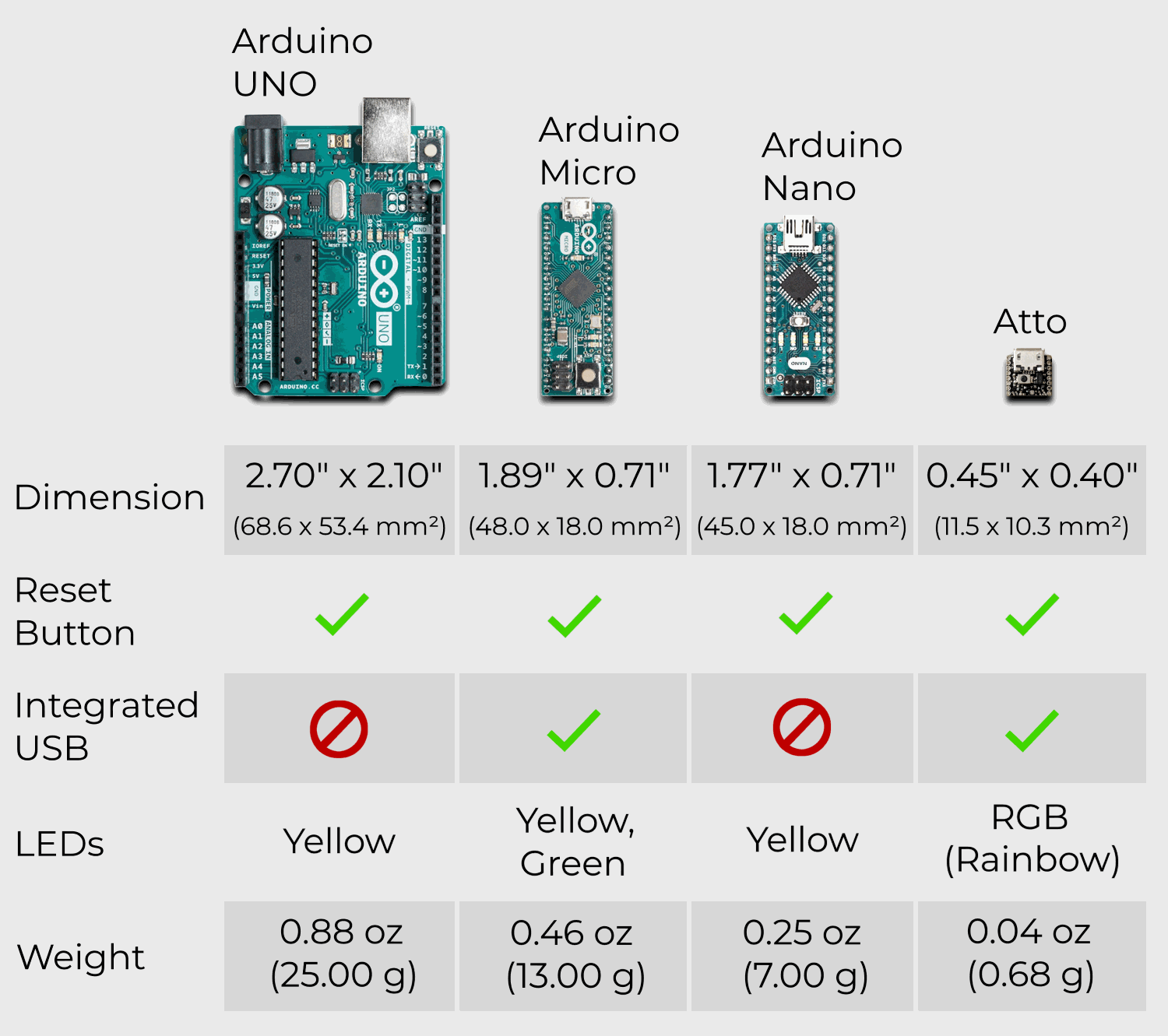
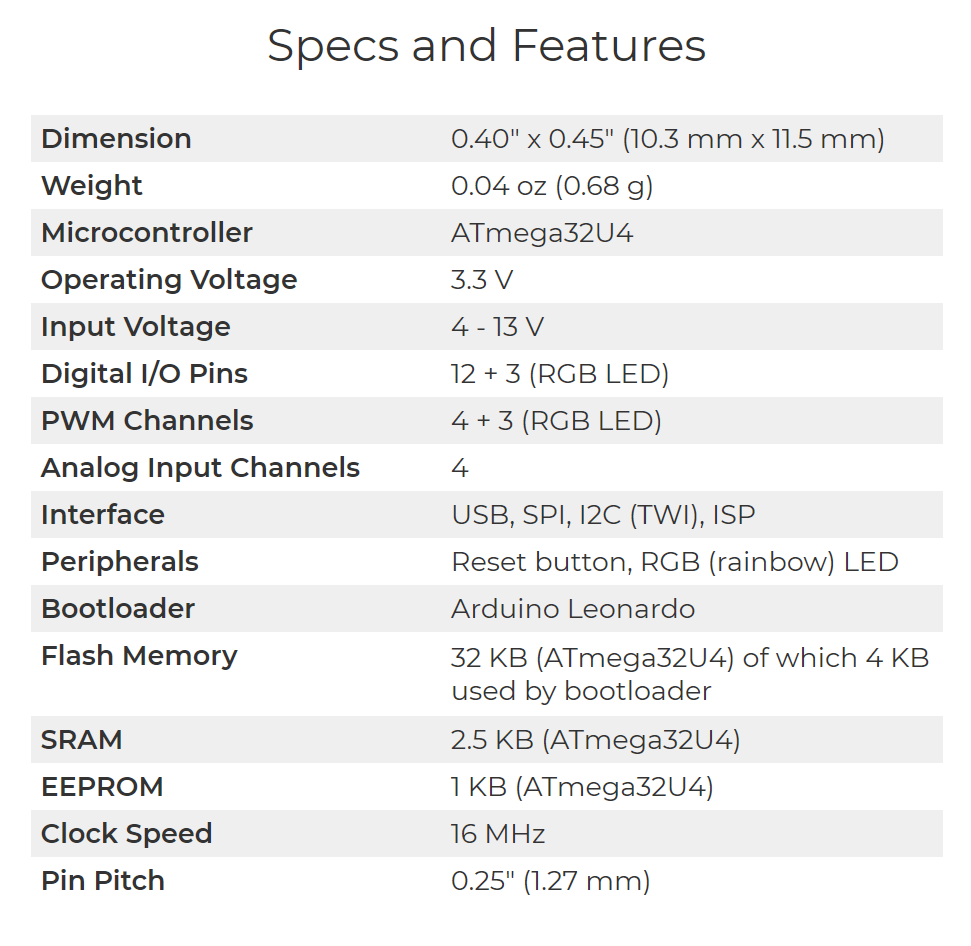
Atto is the world’s smallest Arduino compatible board! It is based on the ATmega32U4 microcontroller and comes with reset push-button as well as an RGB (rainbow) LED controlled by 3 PWM channels.
The new Arduino board is 10.3 mm x 11.5 mm (0.40” x 0.45”) and it has an onboard reset button as well as an RGB (rainbow) LED. There are 16 pins (1.27 mm/0.25” pitch) and the board consists of 12 + 3 (RGB LED) digital I/O, 4 + 3 (RGB LED) PWM, and 4 analog input channels. Supported interfaces on the board include USB, SPI, I2C (TWI), and ISP.
There are also available two different types of breadboard friendly expansion boards and all products from nionics.com are available for pre-order.
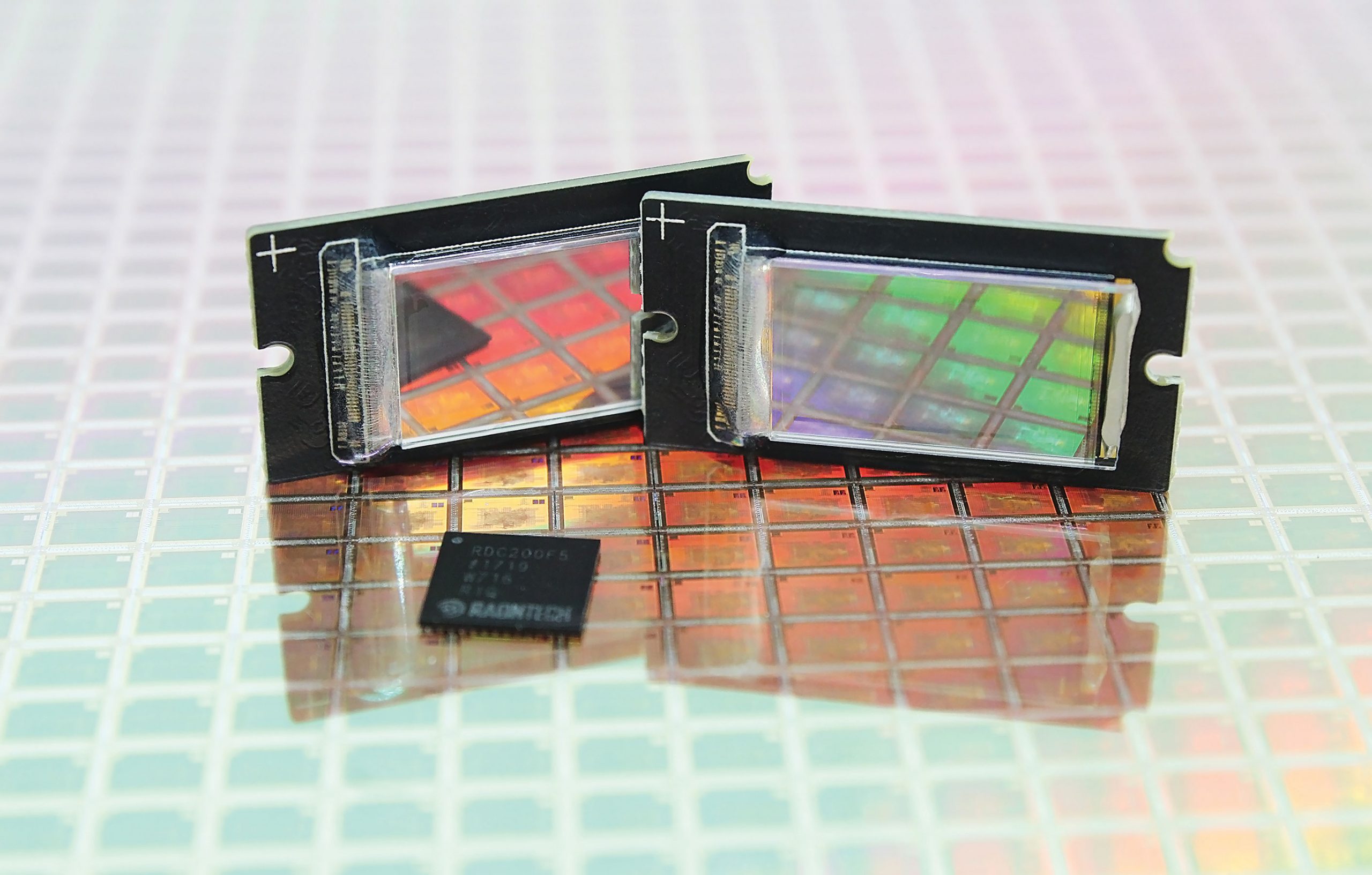
AR and VR display manufacturer Raon-Tech has developed a 0.37-inch diagonal full HD (1920×1080) LCoS micro-display (Liquid Crystal on Silicon) aimed at single panel optical display systems such as HMD (Head Mounted Display), HUD (Head-Up Display), and pico projectors. [via www.eenewsled.com]
Embedding an RGB LED driver, a low voltage differential signal receiver and power-down detection circuitry, the RDP370F LCoS micro-display operates at up to 420Hz for sequential colours, in effect supporting 120 RGB frames per second. Gamma corrected resistor string and gamma tab voltages are fully programmable for enhanced gray scaling performance. The display features an array of 1952×1112 pixel designed at a 4.3μm pitch or approximately 5900 ppi. The device draws only 120mW in operation. Together with the display, Raontech also offers a dedicated controller IC, the RDC200, able to perform image processing along with LED control and data formatting for two microdisplays panels simultaneously. The IC includes a special function to correct keystone and compensate optical aberration, enabling developers to design larger FOV devices with the least distortion.
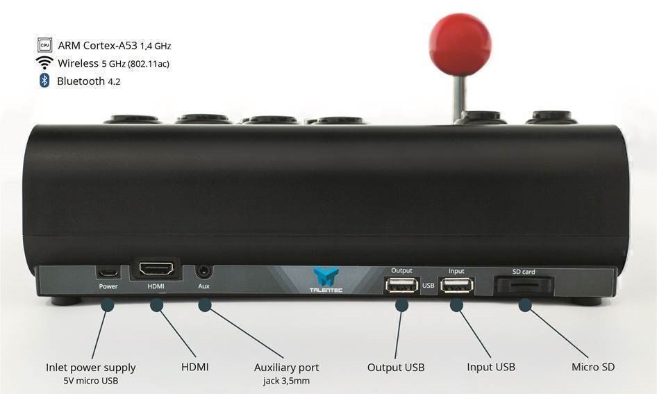
TALENTEC is a Spanish company whose goal is to improve the arcade game experience for players and facilitate this type of entertainment for everyone. To fulfil this premise, they have been working to develop a new concept for the arcade sticks, a smart arcade stick: the RasPi Arcade Stick. In order to check the reception of this product, this company has launched a crowdfunding campaign in kickstarter.
The RasPi Arcade stick is an arcade joystick, with an integrated Raspberry Pi 3 B+. It connects directly to the TV/Monitor vía HDMI and the Raspberry is in charge of making video game emulator. Other features can also be found: a module for SD Card memories and micro USB like power for mobile phones. The processor of this model of Raspberry is an ARM Cortes- A53 that includes wifi ac and Bluetooh 4.2.
Although emulators or the ROMS are not included, it has been tested with RetroPie, Recalbox, Batocera, Lakka and as a media center with Kodi. What’s more, it can be used as a conventional USB arcade stick compatible with PC, PS3 and PS4 in legacy mode.
This gadget will be only sold if the crowdfunding goal is reached and depending on the models and the version, the price is between 54€ and 169€. The project is live on kickstarter and has 12 days to go.
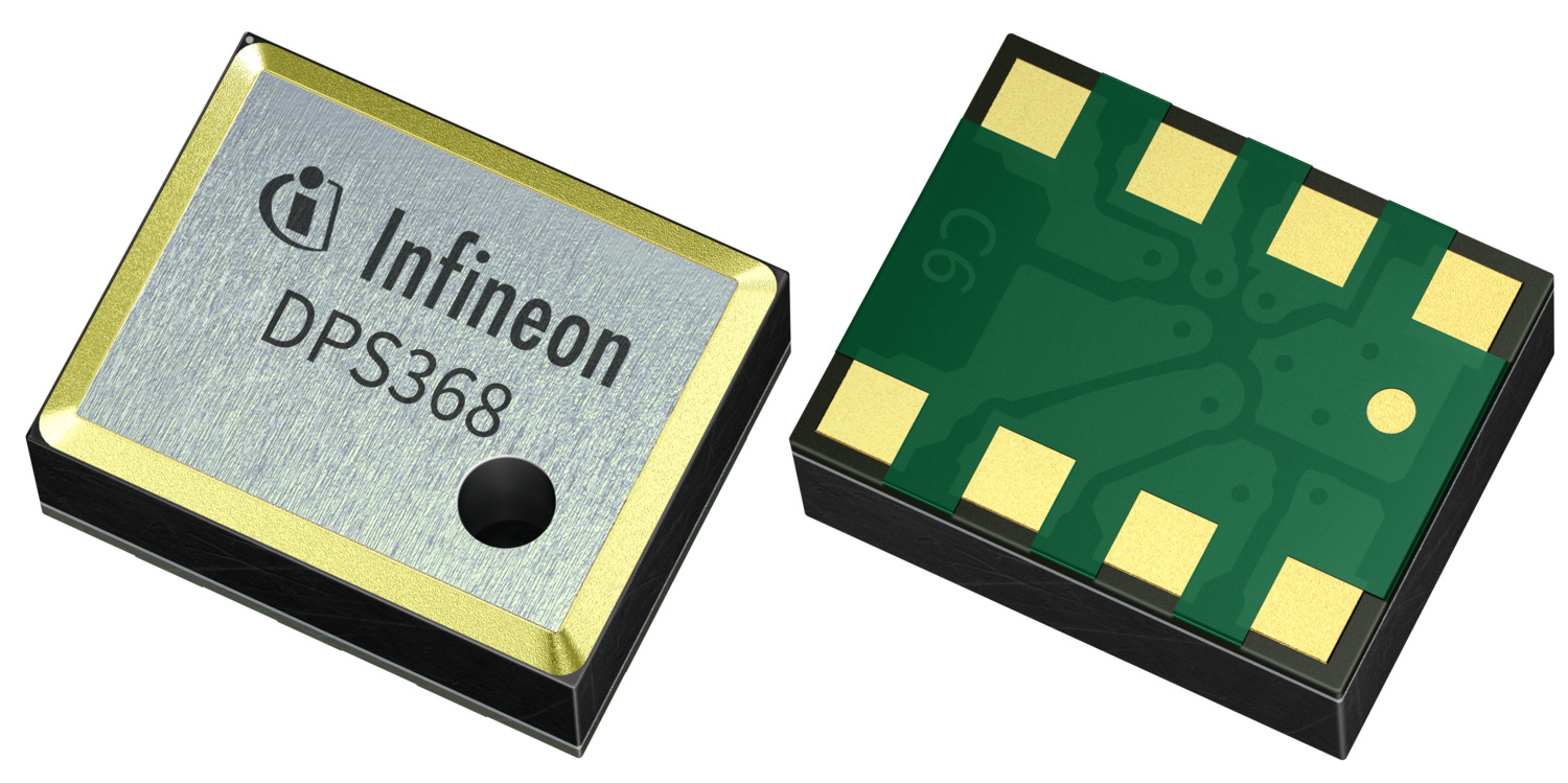
Infineon Technologies AG launches the XENSIV TMDPS368. The miniaturized digital barometric pressure sensor is capable of measuring both pressure and temperature. It offers an ultra-high precision of ±2 cm and a low current consumption for precise measurement of altitude, air flow and body movements. This makes the DPS368 ideal for mobile applications and wearable devices offering e.g. activity tracking and navigation. Additionally the sensor can be used in home appliances for airflow control, in drones for flight stability and in medical devices such as smart inhalers.
Due to its robust package, it can withstand 50 m under water for one hour (IPx8) and protects the sensing cells against dust and humidity. As a result, the board handling in an assembly line is also facilitated. The 8-pin LGA package with its small dimensions of 2.0 x 2.5 x 1.1 mm³ saves up to 80 percent space compared to other waterproof sensors.
The pressure sensor element is based on a capacitive sensing principle that guarantees high precision even during temperature changes. The internal signal processor converts the output from the pressure and temperature sensor elements to 24-bit results. Calibration coefficients stored in the sensor are used in the application to convert the measurement results to high accuracy pressure and temperature values. DPS368 provides quick feedback due to a measurement rate of up to 200 Hz and fast read-out speed. The integrated FIFO memory can save up to 32 measurement results, allowing for power-savings on system level.
The XENSIV DPS368 sensor features an average low power consumption of 1.7 μA for pressure measurements at 1 Hz sampling rate. In standby mode, this is reduced to 0.5 μA. The sensor operates at pressure ranges from 300 to 1200 hPa and temperature ranges from -40 to +85 °C with a temperature accuracy of ±0.5 °C. Sensor measurements and calibration coefficients are available through the serial I²C or SPI interface.
The XENSIV DPS368 pressure and temperature sensor can be ordered now. More information is available at www.infineon.com/DPS368.


