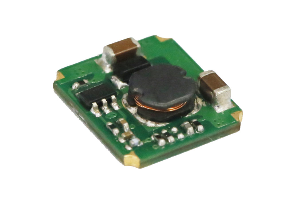
Designed for applications requiring non-isolated step-down circuits, Mornsun’s K78-JT-500R3 Series of open frame non-isolated DC-DC converters is only 3.50mm thick, with an SMD package footprint of 12.50×13.50mm.
The new series provides an ultra-wide input voltage range of 4.75 to 36V and an operating temperature ranging from -40 to +85°C, removing the need for a heat sink. The K78-JT-500R3 Series delivers an efficiency up to 95%, features low stand-by power consumption and short-circuit protection, which can be widely used for applications in industrial control. Depending on the part number, the DC-DC converter outputs 500mA at 3.3 to 15V.
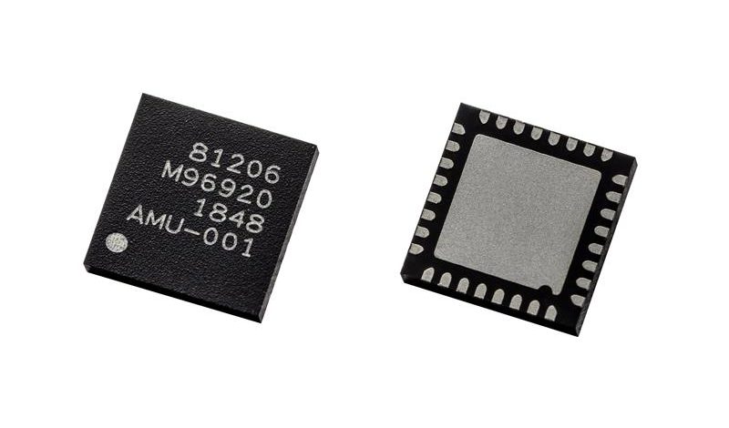
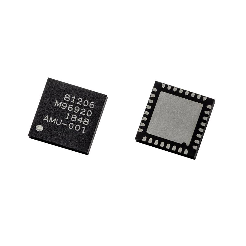
Latest generation II motor predriver offers more Flash memory, LIN interface and easy sensor integration.
Melexis announces the latest addition to its generation II embedded motor driver product portfolio for automotive applications, with the release of the MLX81206. This single-chip solution with 64 KB Flash memory offers higher integration with the ability to drive BLDC motors from 100 W to 1,000 W.
The MLX81206 supports a LIN 1.x/LIN 2.x and SAE J602 compliant interface, the most widely used digital communications interface standards in the automotive sector, making it a simple solution to predriving a range of high-power BLDC motors. With the ability to drive 12 V motors in either a sensor or sensorless configuration the MLX81206 is the ideal choice for silent and high-performance HVAC blowers, engine cooling fans and pumps in conventional, hybrid and full electric vehicles.
Melexis engineers have achieved a high level of integration, bringing together an embedded driver with high-voltage analog circuitry and digital technology, including Flash and non-volatile RAM memory along with an embedded microcontroller. This makes the MLX81206 a highly efficient and complete single-chip solution combining both hardware and software.
The synergy between sensing and drive control makes the MLX81206 a compelling choice in terms of size, performance and robustness. This is apparent by the ease with which the device can interface to a range of sensors, such as the MLX90380 resolver for dynamic pumps driven in Field-Oriented-Control (FOC) mode. This IC can be delivered in a small footprint QFN32 package (MLX81206) or in a leaded package TQFP48 (MLX81208).
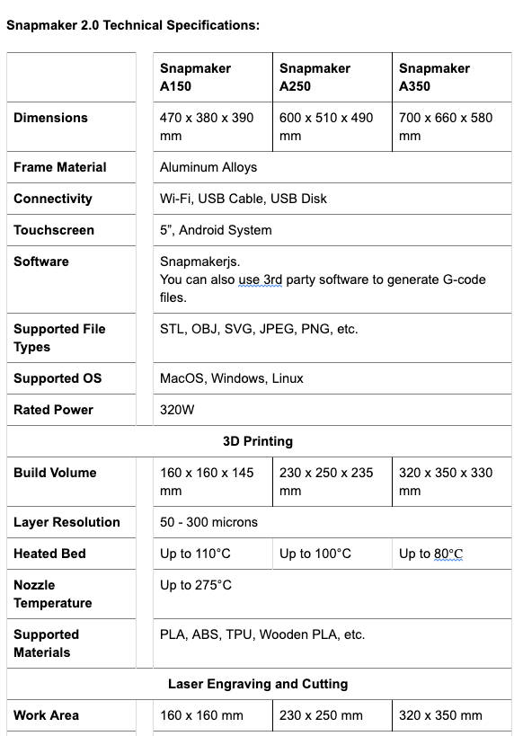
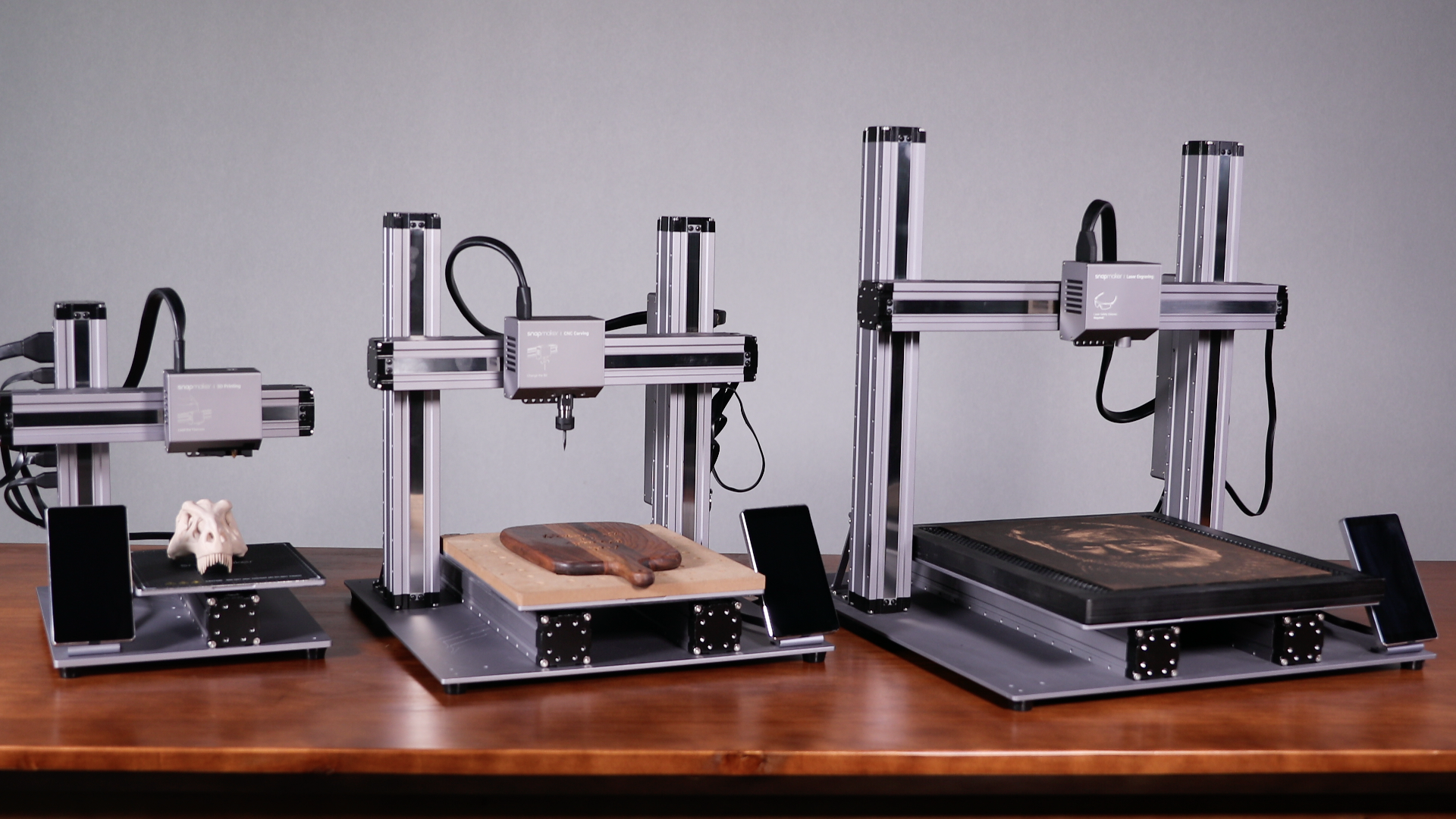
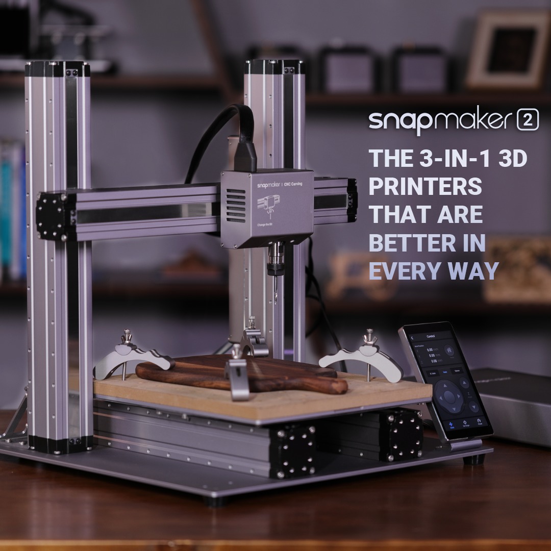
Snapmaker, the 3D printer brand that had the second most funded and fulfilled 3D printing campaign on Kickstarter, has secured another crowdfunding success with the launch of the Snapmaker 2.0.
Having raised over $2M in only an hour on Kickstarter, the Snapmaker 2.0 is the latest generation of 3-in-1 3D printers from Snapmaker. Available in 3 models of different sizes – the A150, A250 and A350 – the 3D printers feature key improvements over the Snapmaker Original, released in 2017. Kickstarter backers will begin receiving their Snapmaker 2.0 orders in November 2019.
The Snapmaker community has always been passionate, and it is inspiring to see such a strong response to our newest 3D printer line,” said Daniel Chen, CEO of Snapmaker. “With the success of this campaign, Snapmaker is even closer to reaching our goal of fabrication devices for everyone that strike the perfect balance between high-quality and affordability. We can’t wait for our backers to get their Snapmaker 2.0s and start creating!
The Snapmaker 2.0 resonates with backers thanks to the modular design, thoughtful details, and highly requested features from the community, including:
3-in-1 capabilities for 3D printing, laser engraving and cutting, and CNC carving
Compatibility with dozens of everyday materials such as leather and food items, to popular 3D printing materials like wooden PLA
A modular design so users can easily upgrade their machine with new modules in the future
High quality metal construction with aerospace-grade aluminum alloys
A large workspace with each model of different sizes so you can make large projects or multiple smaller objects at once
Intuitive touchscreen and software to control the printers, and also select and preview your projects
3-in-1 software
Our 3-in-1 software, Snapmakerjs, is tailor-made for your Snapmaker machines. One single and powerful software for all your tasks. It has been iterated through 18 versions over the last one and a half years, adding features like multiple models printing/engraving/cutting/carving, SVG editing, relief carving, and multiple language support. Using rapid iterations, we’ve included many popular requests from our community.
We really appreciate the help and patience from the Kickstarter and open source community. You helped us learn and grow. Now it’s our turn to contribute. We decided to open source Snapmakerjs and firmware in November when the first batch of Snapmaker 2.0 is shipped. With a plugin system, API and tutorials, Snapmakerjs enables you to easily add new features for existing modules. You can even develop new features for your customized modules. We will build a truly modular system together.
CNC Highlights
Snapmaker 2.0 features a fully upgraded CNC module. Using the standard ER11 Collet, it guarantees a better concentricity that allows for faster CNC carving speed and larger step down, which saves your time significantly. It also supports over one hundred carving and cutting bits. The diameters of the bits range from 0.5mm (0.020 inches) to 6.35mm (0.250 inches).
Kickstarter campaign backers will start receiving their orders in November 2019.
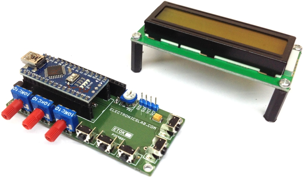
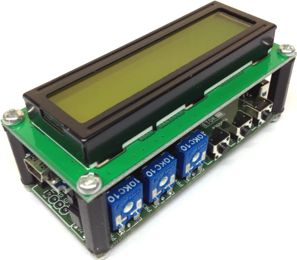
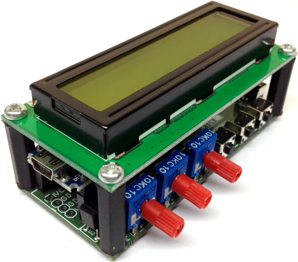
This 16×2 LCD shield for Arduino Nano includes various addons, like 5 Tactile Switches, 3 Trimmer Potentiometers, LM35 Temperature sensor and the 16×2 LCD itself. It’s a compact shield designed to fit in small enclosures and it is intended to develop measuring devices like thermometers, voltmeters, timers, up down counters and other various project requiring LCD, switches, trimmer pots etc.
Features
Input Supply 7-12V DC
16×2 LCD Header Connector
5 Vertical Mounted Push Switch
3 x 5K Ohms Trimmer Potentiometers
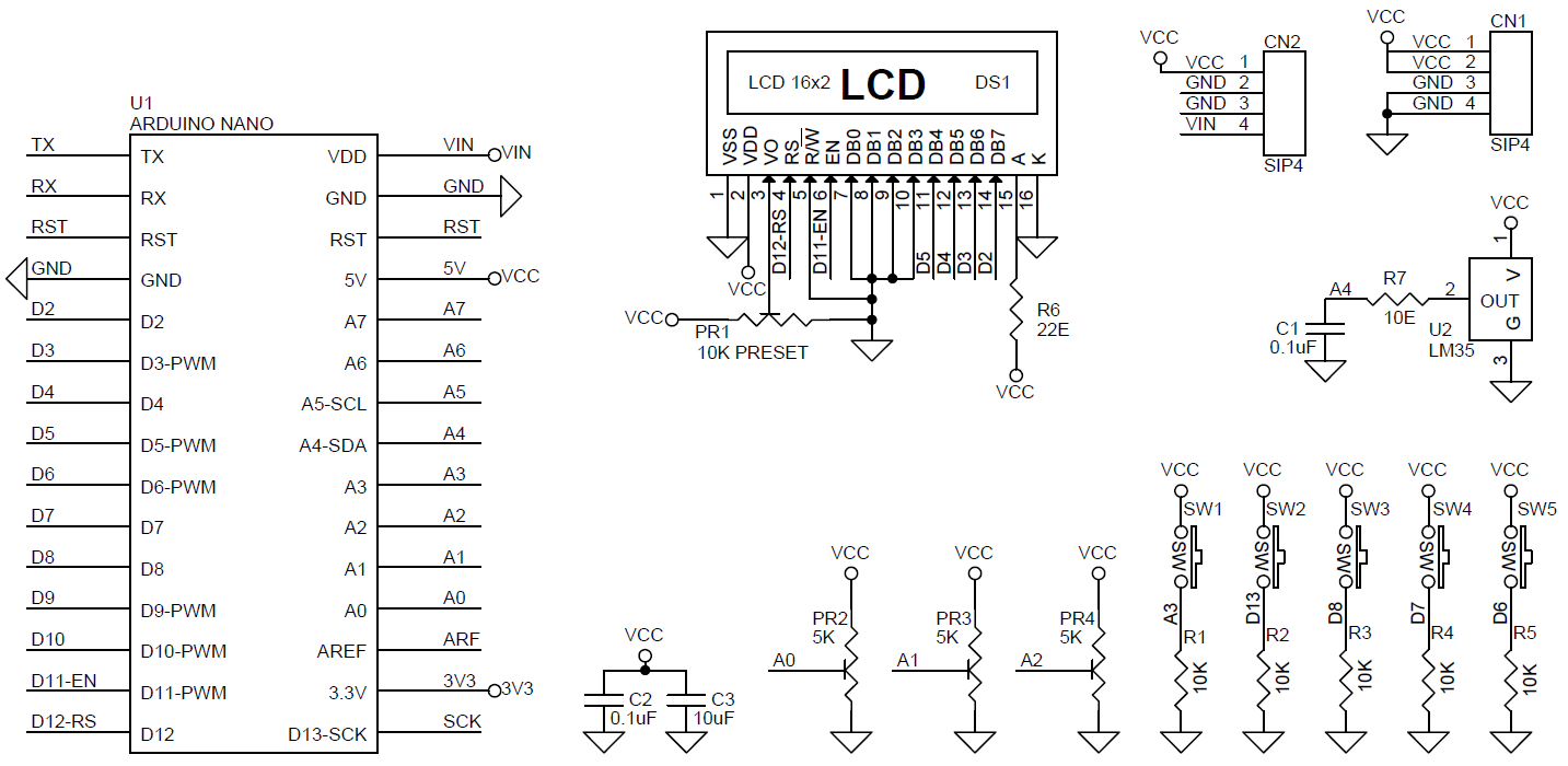
LCD Connected to D2,D3,D4,D5,D11,D12
LM35 Temperature Sensor Connected Analog- A4 of Arduino
Trimmer Potentiometer Connected to Analog Pin A0,A1,A2
Push Switch Connected to A4, D13, D8, D7, D6
PR1 Trimmer Potentiometer To Adjust The LCD Contrast
This 16×2 LCD shield for Arduino Nano includes various addons, like 5 Tactile Switches, 3 Trimmer Potentiometers, LM35 Temperature sensor and the 16×2 LCD itself. It’s a compact shield designed to fit in small enclosures and it is intended to develop measuring devices like thermometers, voltmeters, timers, up down counters and other various project requiring LCD, switches, trimmer pots etc.
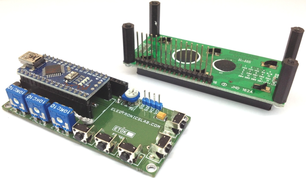
Note : Trimmer Potentiometer can be replaced with Header connector to interface various sensors.
Features
Input Supply 7-12V DC
16×2 LCD Header Connector
5 Vertical Mounted Push Switch
3 x 5K Ohms Trimmer Potentiometers
LM35 Temperature Sensor
LCD Connected to D2,D3,D4,D5,D11,D12
LM35 Temperature Sensor Connected Analog- A4 of Arduino
Trimmer Potentiometers Connected to Analog Pin A0,A1,A2
Push Switch Connected to A4, D13, D8, D7, D6
PR1 Trimmer Potentiometer To Adjust The LCD Contrast
A few weeks ago, we examined the features of ESP32 module and built a simple hello world program to get ourselves familiar with the board. Today, we will continue our exploration of the ESP32 on a higher level as we will look at how to interface a 16×2 LCD with it.
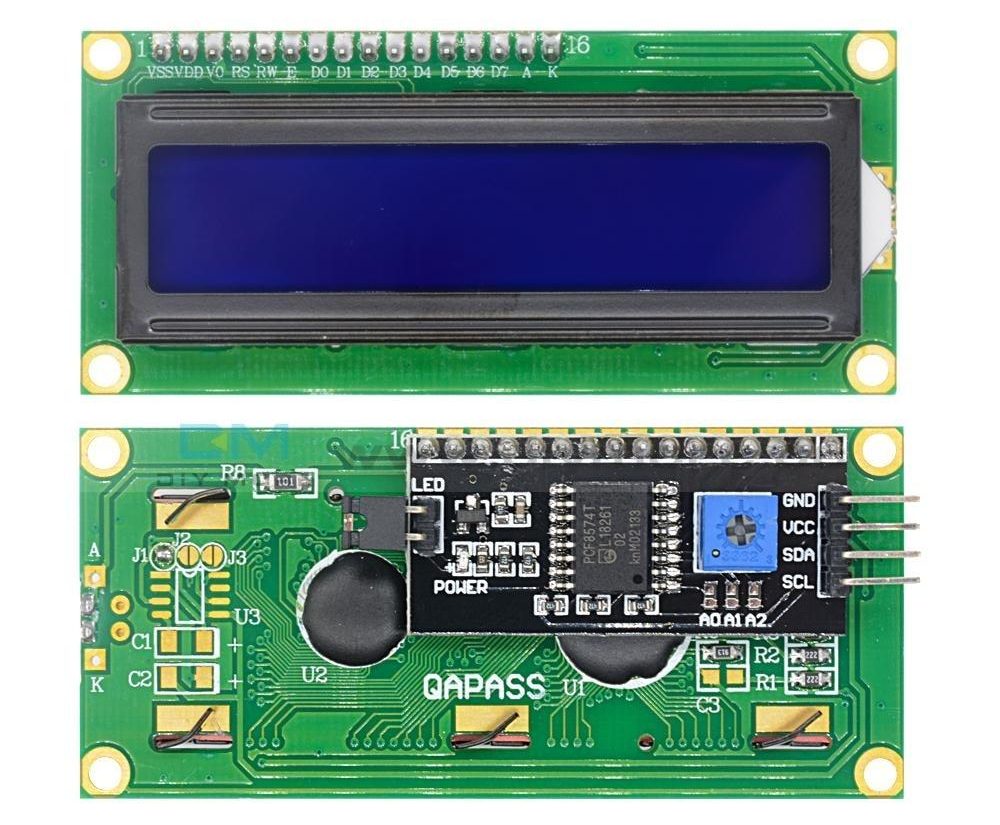
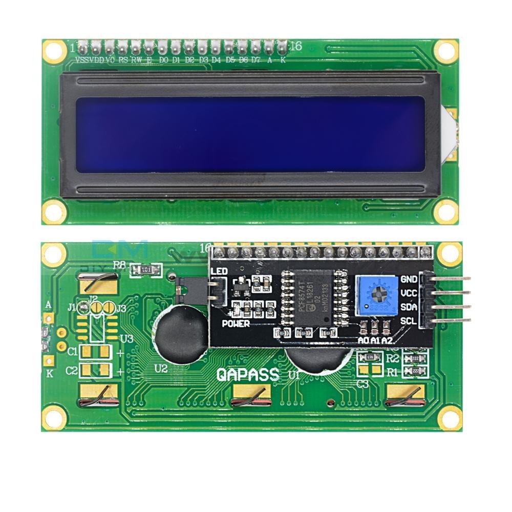
Displays provide a fantastic way of providing feedback to users of any project and with the 16×2 LCD being one of the most popular displays among makers, and engineers, its probably the right way to start our exploration. For today’s tutorial, we will use an I2C based 16×2 LCD display because of the easy wiring it requires. It uses only four pins unlike the other versions of the display that requires at least 7 pins connected to the microcontroller board.
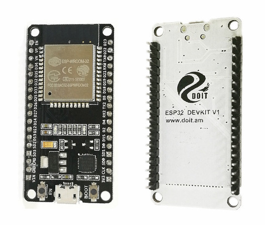
ESP32 comes in a module form, just like its predecessor, the ESP-12e, as a breakout board is usually needed to use the module. Thus when it’s going to be used in applications without a custom PCB, it is easier to use one of the development boards based on it. For today’s tutorial, we will use the DOIT ESP32 DevKit V1 which is one of the most popular ESP32 development boards.
To demonstrate the use of I2C driven LCD with the NodeMCU, we will examine how to display both static and scrolling messages on the LCD.
A few weeks ago, we examined the features of ESP32 module and built a simple hello world program to get ourselves familiar with the board. Today, we will continue our exploration of the ESP32 on a higher level as we will look at how to interface a 16×2 LCD with it.
I2C 16×2 LCD Display
Displays provide a fantastic way of providing feedback to users of any project and with the 16×2 LCD being one of the most popular displays among makers, and engineers, its probably the right way to start our exploration. For today’s tutorial, we will use an I2C based 16×2 LCD display because of the easy wiring it requires. It uses only four pins unlike the other versions of the display that requires at least 7 pins connected to the microcontroller board.
DOIT ESP32 DevKit V1
ESP32 comes in a module form, just like its predecessor, the ESP-12e, as a breakout board is usually needed to use the module. Thus when it’s going to be used in applications without a custom PCB, it is easier to use one of the development boards based on it. For today’s tutorial, we will use the DOIT ESP32 DevKit V1 which is one of the most popular ESP32 development boards.
To demonstrate the use of I2C driven LCD with the NodeMCU, we will examine how to display both static and scrolling messages on the LCD.
Required Components
The following components are required to build this project;
DOIT ESP32 DevKit V1 board
Breadboard
A 16×2 I2C LCD display
Jumper Wires
The breadboard requirement is optional as you can choose to connect the LCD directly to the DOIT devkit board using female-female jumper wires.
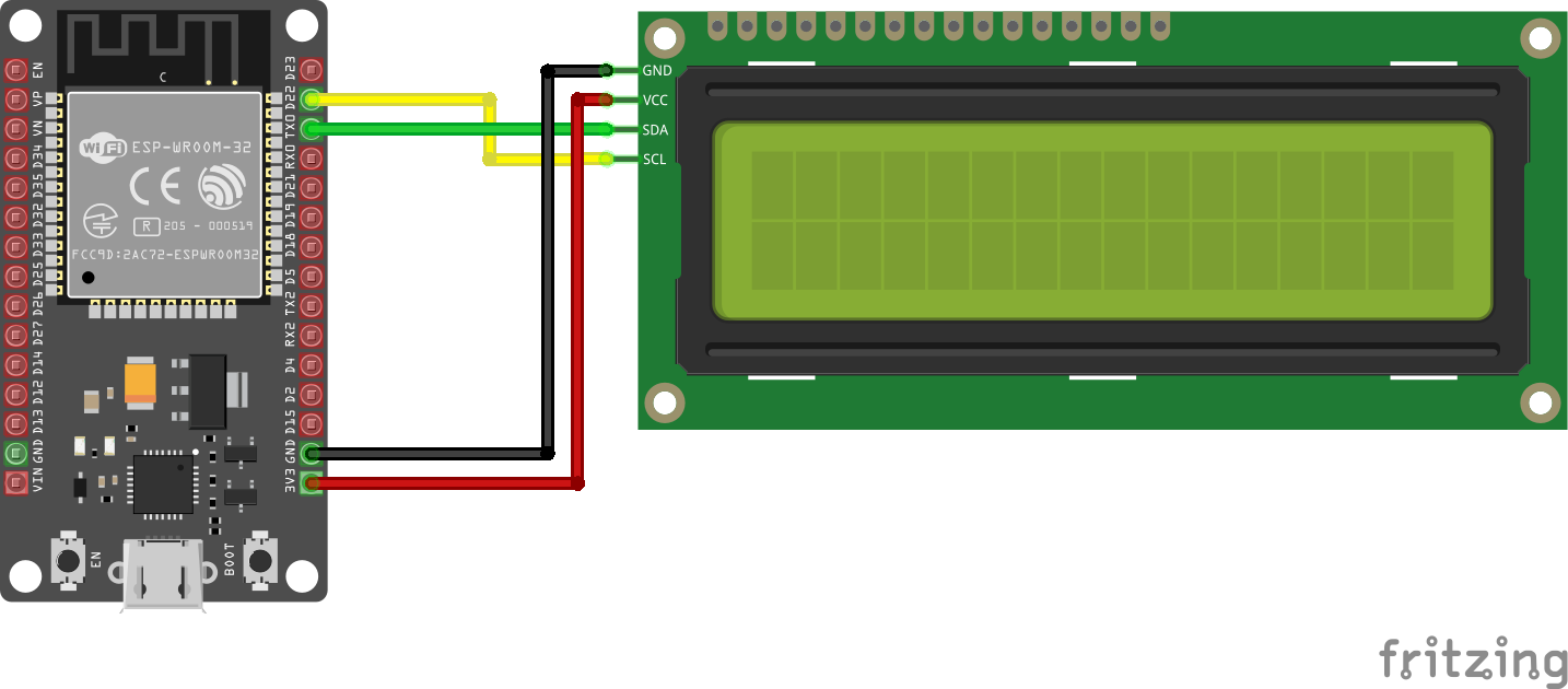
Schematics
The schematics for this project is relatively simple since we are connecting just the LCD to the DOIT Devkit v1. Since we are using I2C for communication, we will connect the pins of the LCD to the I2C pins of the DevKit. Connect the components as shown below.
Schematics
A pin map showing how the components are connected is shown below.
Due to the power requirements of the LCD, it may not be bright enough when connected to the 3.3v pin of the ESP32. If that is the case, connect the VCC pin of the LCD to the Vin Pin of the ESP32 so it can draw power directly from the connected power source.
Detecting the I2C Address of the LCD
At this point, it is important to note that a special setup is required to enable you to use the Arduino IDE to program ESP32 based boards. We covered this in the introduction to ESP32 tutorial published a few weeks go. So, be sure to check it out.
To be able to easily write the code to interact with the I2C LCD display, we will use the I2C LCD library. The Library possesses functions and commands that make addressing the LCD easy. Download the I2C LCD library from the link attached and install on the Arduino IDE by simply extracting it into the Arduino’s library folder.
Before writing the code for the project, it’s important for us to know the I2C address of the LCD as we will be unable to talk to the display without it.
While some of the LCDs come with the address indicated on it or provided by the seller, in cases where this is not available, you can determine the address by using a simple sketch that sniffs the I2C line to detect what devices are connected alongside their address. This sketch is also a good way to test the correctness of your wiring or to determine if the LCD is working properly.
Copy the code below and paste in the Arduino IDE.
#include <Wire.h>

void setup() {
  Wire.begin();
  Serial.begin(115200);
  Serial.println("\nI2C Scanner");
}

void loop() {
  byte error, address;
  int nDevices;

  Serial.println("Scanning...");

  nDevices = 0;
  for(address = 1; address < 127; address++ )
  {
    // The i2c_scanner uses the return value of
    // the Write.endTransmisstion to see if
    // a device did acknowledge to the address.
    Wire.beginTransmission(address);
    error = Wire.endTransmission();
    if (error == 0) {
      Serial.print("I2C device found at address 0x");
      if (address<16) {
        Serial.print("0");
      }
      Serial.println(address,HEX);
      nDevices++;
    }
    else if (error==4) {
      Serial.print("Unknow error at address 0x");
      if (address<16) {
        Serial.print("0");
      }
      Serial.println(address,HEX);
    }
  }
  if (nDevices == 0) {
    Serial.println("No I2C devices found\n");
  }
  else {
    Serial.println("done\n");
  }
  delay(5000);
}
This sketch basically uses a “for” loop to generate a list of addresses and then sends a begin transmission request to the address. The return value of the Write.endTransmission() function shows if a device exists on that particular address. The address at which a response was received is the address we are a looking for.
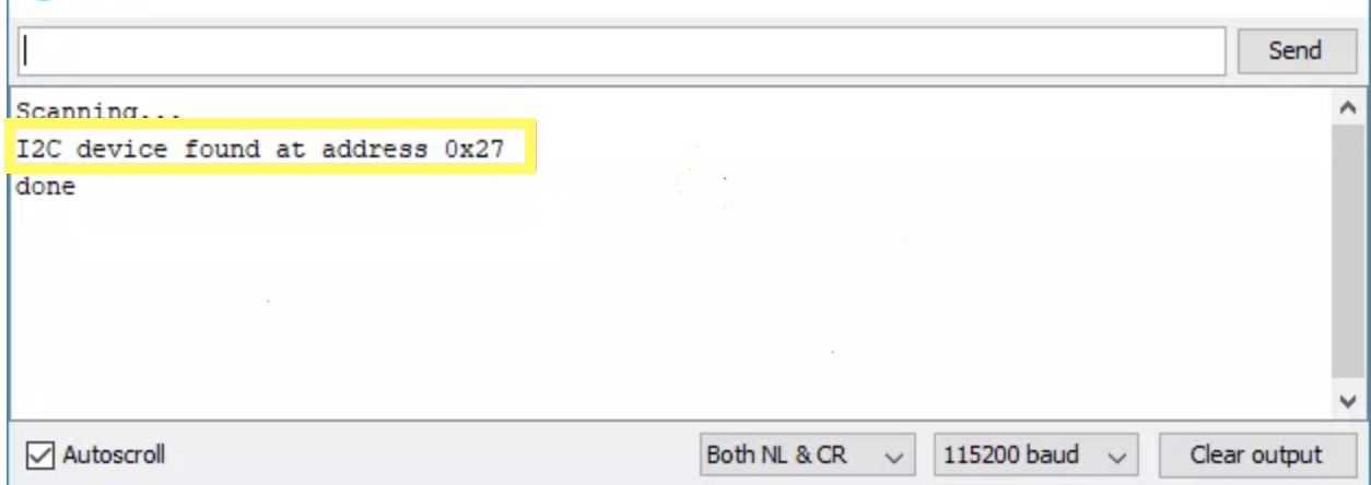
Verify and upload the code to the ESP32 Board and open the serial monitor. You should see the address as shown in the image below:
Device Address
If you keep getting “no devices found”, it might help to take a look at the connections to be sure you didn’t mix things up and you could also go ahead and try 0x27 as the I2C address. This is a common address for most I2C LCD modules from China.
Armed with the address, we can now write the code for this project.
Code
Our task for today’s tutorial is to display both static and scrolling text on the LCD, and to achieve that, we will use the I2C LCD library to reduce the amount of code we need to write. We will write two separate sketches; one to display static texts and the other to display both static andscrolling text.
Static Text
To start with the sketch for static text display, we start the code by including the library to be used for it, which in this case, is the I2C LCD library.
#include <LiquidCrystal_I2C.h>
Next, we create an instance of the I2C LCD library class with the address of the display, the number of columns the display has (16 in this case), and the number of rows (2 in this case) as arguments.
LiquidCrystal_I2C lcd(0x27, 16, 2);
With that done, we proceed to the void setup() function. Here we initialize the display and issue the command to turn the backlight on as it might be off by default depending on the LCD.
Next is the void loop() function. The idea behind the code for the loop is simple, we start by setting the cursor to the column and row of the display where we want the text to start from, and we proceed to display the text using the lcd.print() function. To allow the text to stay on the screen for a while (so its visible) before the loop is reloaded, we delay the code execution for 1000ms.
void loop(){
// set cursor to first column, first row
lcd.setCursor(0, 0);
// print message
lcd.print("Hello, World!");
delay(1000);
// clears the display to print new message
}
The complete code for the project is available below and also attached under the download section.
#include <LiquidCrystal_I2C.h>
// set LCD address, number of columns and rows
// if you don't know your display address, run an I2C scanner sketch
LiquidCrystal_I2C lcd(0x27, 16, 2);
void setup(){
  // initialize LCD
  lcd.init();
  // turn on LCD backlight
  lcd.backlight();
}
void loop(){
  // set cursor to first column, first row
  lcd.setCursor(0, 0);
  // print message
  lcd.print("Hello, World!");
  delay(1000);
  // clears the display to print new message
}
Scrolling Text
For the scrolling text, we will use some code developed by Rui Santos of RandomNerdTutorials.com. This code allows the display of static text on the first row and scrolling text on the second row of the display at the same time.
As usual, we start by including the libraries that we will use for the sketch which in this case is the same I2C LCD library.
Next, we create an instance of the I2C LCD library class with the address of the display, the number of columns the display has (16 in this case), and the number of rows (2 in this case) as arguments.
LiquidCrystal_I2C lcd(0x27, 16, 2);
Next, we create variables to hold the messages to be displayed.
String messageStatic = "Static message";
String messageToScroll = "This is a scrolling message with more than 16 characters";
Next, we create the function to display scrolling text. The function accepts four arguments; the row on which to display the scrolling text, the text to be displayed, the delay time between the shifting of characters, and the number of columns of the LCD.
void scrollText(int row, String message, int delayTime, int lcdColumns) {
  for (int i=0; i < lcdColumns; i++) {
    message = " " + message;
  }
  message = message + " ";
  for (int pos = 0; pos < message.length(); pos++) {
    lcd.setCursor(0, row);
    lcd.print(message.substring(pos, pos + lcdColumns));
    delay(delayTime);
  }
}
Next is the void setup() function. The function stays the same as the one for the static text display as we initialize the display and turn on the backlight.
With that done, we move to the void loop() function. We start by setting the cursor, then we use the print function to display the static text and the scrollText() function is called to display the scrolling text.
void loop(){
// set cursor to first column, first row
lcd.setCursor(0, 0);
// print static message
lcd.print(messageStatic);
// print scrolling message
scrollText(1, messageToScroll, 250, lcdColumns);
}
The complete code for this sketch is available below and also attached under the download section of the tutorial.
// Adapted from the code by
// Rui Santos
// https://randomnerdtutorials.com
#include <LiquidCrystal_I2C.h>
// if you don't know your display address, run an I2C scanner sketch
LiquidCrystal_I2C lcd(0x27, 16, 2);
String messageStatic = "Static message";
String messageToScroll = "This is a scrolling message with more than 16 characters";
// Function to scroll text
// The function acepts the following arguments:
// row: row number where the text will be displayed
// message: message to scroll
// delayTime: delay between each character shifting
// lcdColumns: number of columns of your LCD
void scrollText(int row, String message, int delayTime, int lcdColumns) {
for (int i=0; i < lcdColumns; i++) {
message = " " + message;
}
message = message + " ";
for (int pos = 0; pos < message.length(); pos++) {
lcd.setCursor(0, row);
lcd.print(message.substring(pos, pos + lcdColumns));
delay(delayTime);
}
}
void setup(){
  // initialize LCD
  lcd.init();
  // turn on LCD backlight
  lcd.backlight();
}
void loop(){
// set cursor to first column, first row
lcd.setCursor(0, 0);
// print static message
lcd.print(messageStatic);
// print scrolling message
scrollText(1, messageToScroll, 250, 16);
}
Demo
Ensure your connections are properly done, connect the DOIT Devkit to your PC and upload either of the two sketches. You should see this display come up with the text as shown in the image below.
Demo
That’s it for today’s tutorial guys. Thanks for following this tutorial. This cheap LCD display provides a nice way of providing visual feedback for your project and even though the size of the screen and the quality of the display is limited, with the scrolling function you can increase the amount of text/characters that can be displayed.
Feel free to reach out to me via the comment section, with questions and general comments on the tutorial.
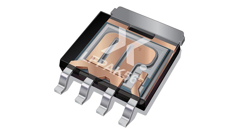
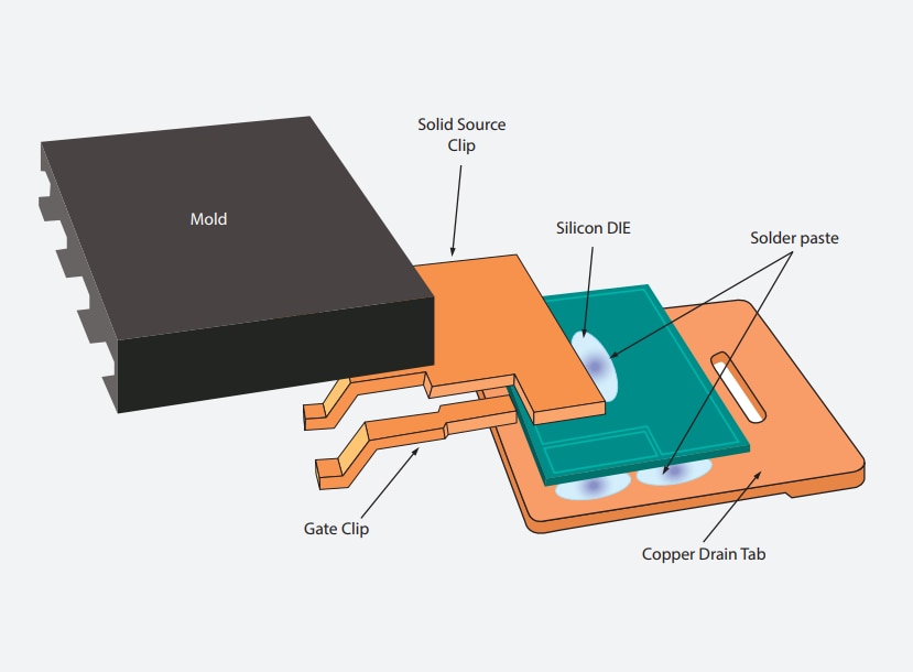
Bipolar transistors in LFPAK56 – the true power package for smart efficiency
These high-power bipolar transistors, housed in LFPAK56 (Power-SO8) packages, deliver DPAK-like thermal and electrical performance in just half the footprint. Offering reliable, energy-efficient performance, they are AEC-Q101 qualified and support high-temperature operation (175 °C).
Features & benefits
27 types up to 100 V and 15 A in single and double confi gurations
High power dissipation (Ptot)
Suitable for high-temperature applications (175 °C)
Space-saving 5 x 6 mm package outline is half the size of equivalent transistors in DPAK, SOT223, and other packages
Low profile (1 mm)
High reliability and mechanical ruggedness thanks to solidcopper clip (no wires)
High energy effi ciency due to less heat generation
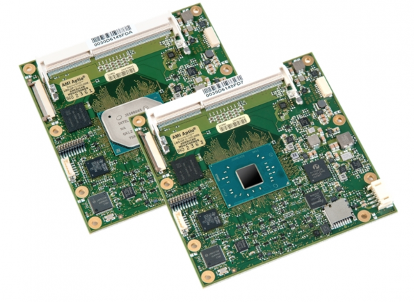
Avnet Integrated has incorporated AMD’s R1000 embedded processor family, based on the Ryzen core architecture, into its COM Express Type 6 modules. The ready-to-use computer on modules (COMs) enable developers to quickly implement the new processor technology in compact embedded systems for a rapid introduction of innovative end products, claims Avnet. The desired performance data can be easily scaled via the processor platform.
The R1000-based module platform in COM Express Compact form factor features high graphics performance that can replace an external solution in price-sensitive applications. Another advantage is the low power dissipation of 12 to 25W. In addition to the R1000 accelerated processing unit (APU) with dual-core, the modules integrate a dual channel DDR4 memory with optional error-correcting code (ECC).
There are common embedded interfaces such as PCI Express and connections for up to three independent 4K displays. Some module variants are designed for the industrial temperature range from -40 to +85 degrees C. The boards, which were developed for the embedded market, are available for at least 10 years from the product launch of the processor, assures Avnet.
Typical areas of use for the R1000-based COM Express module family are applications with high graphics requirements and large data volumes, for example, in medical technology, human machine interface (HMI) systems, gaming and entertainment products.
The R1000 embedded processor family has the same architecture as the AMD V1000 processors. Both processor families are socket-compatible and can be scaled, both in terms of performance and cost, according to the specific application. In addition to the R1000, Avnet Integrated also offers V1000-based product variants to provide customers with the whole range of performance spectrum.
Samples will be available starting August 2019 and volume ramp up expected for the end of 2019.
The company also revealed that integration of R1000 processors into SMARC 2.0 modules is in preparation.
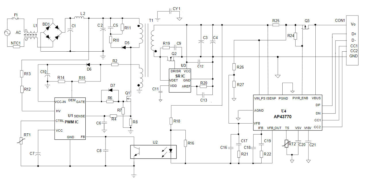
Diodes Incorporated announced the introduction of the AP43770 USB Type-C™ power delivery (PD) controller, a highly integrated solution for implementing PD over USB in fixed and portable devices, and offline power adapters. The AP43770 is well-suited to a range of applications where USB PD is implemented, including AC adapters, power hubs, battery banks, and USB PD converters. It features an embedded microcontroller running firmware compliant with the latest USB Type-C specification and USB PD Revision 3.0 V1.1. Support for Qualcomm® Quick Charge™ (QC) 4/4+ is built into the device. Additionally, the inclusion of QC3.0, QC2.0, and Battery Charging (BC) revision 1.2 and other legacy protocols with auto-detection means that backwards compatibility can be maintained with existing equipment.
The programmable power supply (PPS) feature, introduced with the latest version of the USB PD specification, is also supported by the AP43770. The PPS feature allows the output voltage to vary based on the load requirements; this is communicated using a relevant augmented power data object (APDO). Support for PPS with APDO is implemented in the AP43770 through a constant current and constant voltage (CC/CV) output driver that is adjustable in 50mA steps up to 6A, and 20mV steps between 3V and 20V, respectively.
AP43770 Typical Application Circuit
As USB PD has the potential to deliver high levels of power, the USB eMarker feature is increasingly applied to active cables. The AP43770 includes the necessary support for eMarker technology, in order to detect and identify cables before power is delivered. Cable compensation is also supported.
When coupled with a suitable PWM controller, such as Diodes’ AP3108L, the AP43770 provides a total PD solution. It also features up to 8kb of OTP (for main firmware code) or MTP (for user configurable parameters). MTP memory can be used to set up power specification and protocol options to the manufacturer’s requirements.
The AP43770 is available in the space-saving TSSOP-16 package. Further information is available at www.diodes.com.