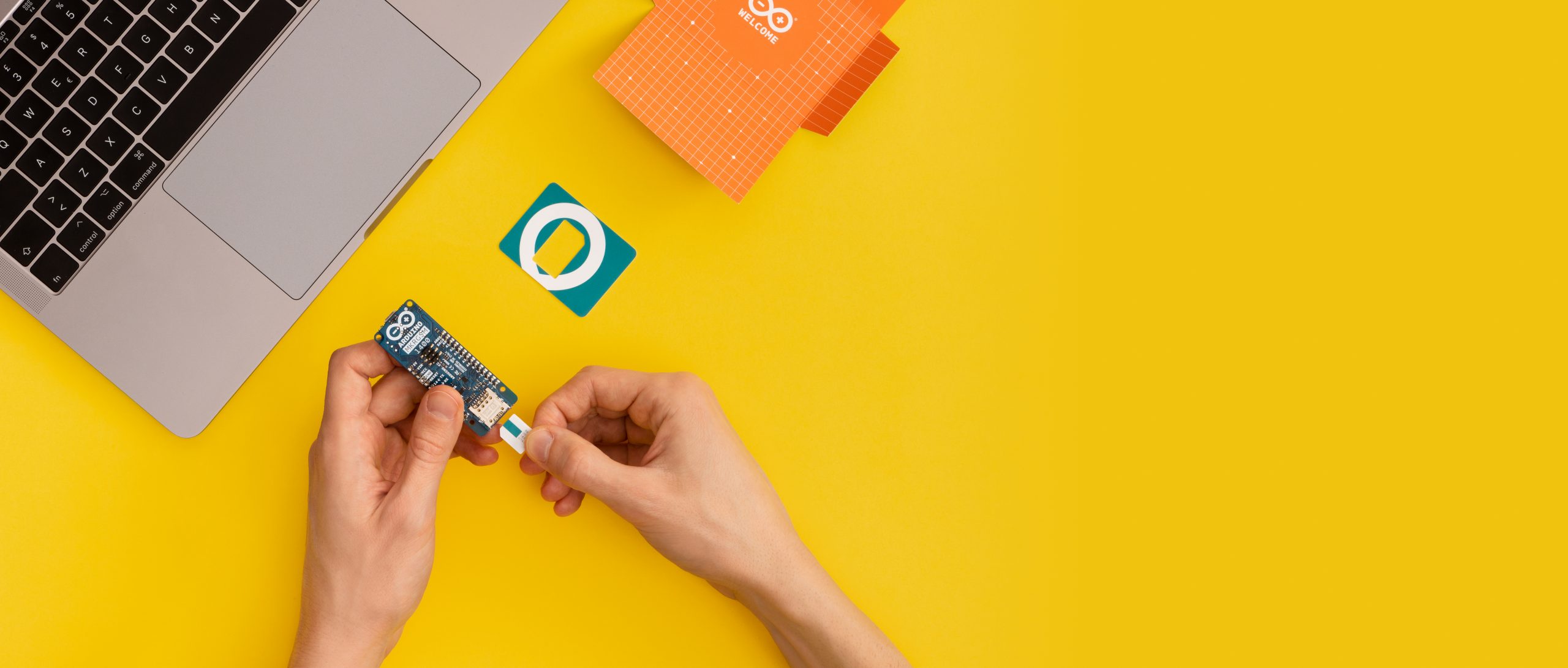
Arduino has launched Arduino SIM, which is a SIM-only service exclusively for IoT (internet of things) devices based on the Arduino platform. It provides developers and manufacturers cellular access to the Arduino IoT Cloud platform from over 100 countries with a single data plan and competitive pricing. [via www.mwee.com]
Arduino SIM aims to provide the simplest path to cellular IoT device development in an environment familiar to millions. The cellular service, provided by Arm® Pelion™ Connectivity Management, means a single physical Arduino SIM can be used in over 100 countries worldwide with one simple data plan. The Arduino SIM data plan is launching initially in the US, with availability in Europe and Asia to follow in summer 2019.
Fully integrated with Arduino IoT Cloud, Arduino SIM is continuing Arduino’s mission to democratize IoT technology, making cellular IoT accessible to everyone from makers to professionals across domains already using Arduino today, including in education, agriculture, industrial, retail and more. Users can easily send sensor data to databases, spreadsheets or alerts, without any coding necessary, using Webhooks, or are able to create custom IoT applications using the API.
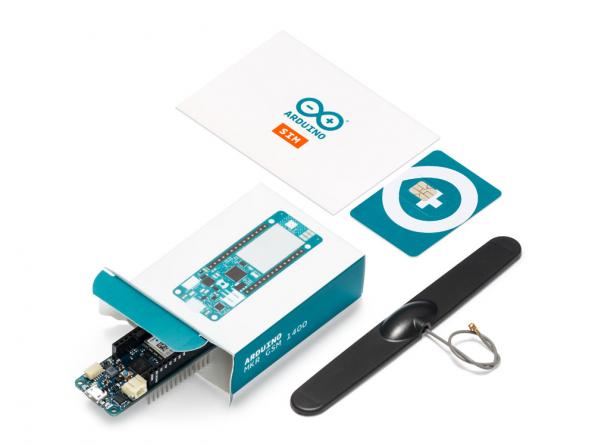
Arduino MKR GSM 1400
Arduino SIM is initially rolling out with support for Arduino MKR GSM 1400 (3G with 2G fallback), which is a 32-bit Arduino board supporting TLS and X.509 certificate-based authentication through an on-board secure element and crypto-accelerator. Arduino IoT Cloud makes it possible for anyone to connect to these boards securely without any coding required, but they are still programmable using open-source libraries and the traditional Arduino IDE. A roadmap is in place to support the upcoming Arduino MKR NB 1500 (LTE Cat-M and NB-IoT), with plans to open it to third party cellular boards at a later date.
From prototype to production
Arduino SIM provides a streamlined path for cellular IoT development with 10 MB of data free for up to 90 days, and the option for a simple subscription at 5 MB for $1.50 USD per month. The one simple plan provides the same amount of data traffic for the same price wherever in the world the device is being operated. By partnering with Arm Pelion Connectivity Management, the cellular service has a solid foundation for users planning to scale to large numbers of devices in the future.
Fabio Violante, CEO of Arduino said:
SIM is a way to simplify cellular connection to Arduino IoT Cloud. By partnering with Arm Pelion Connectivity Management we’re able to offer global data plans to suit everything from single IoT prototypes to production IoT deployments. The simplicity of integration with Arm Pelion Connectivity gives us the freedom to focus on our users; and accelerating innovation and adoption in cellular IoT.
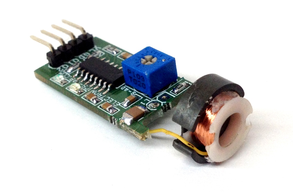
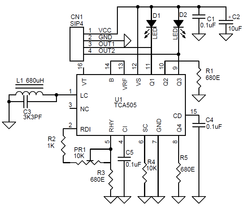
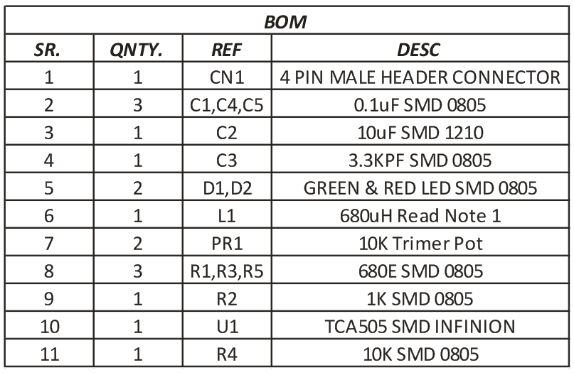
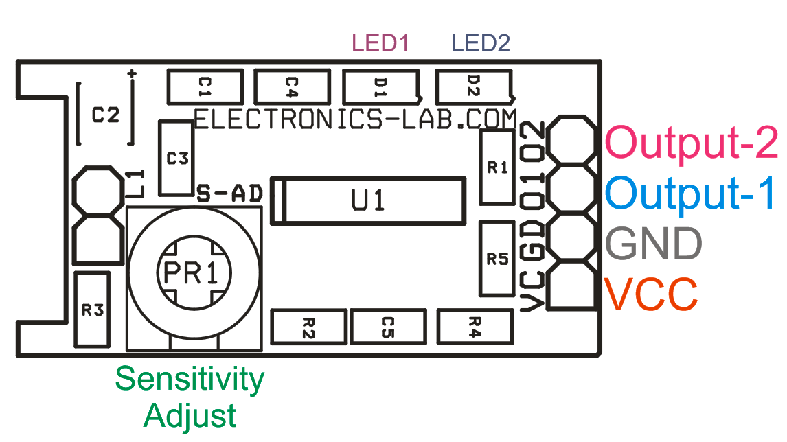
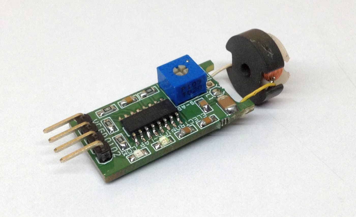
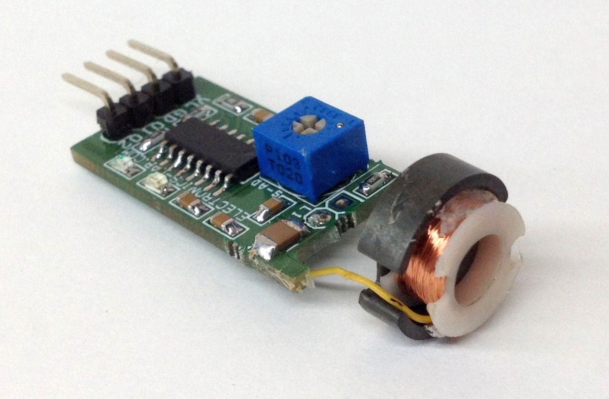
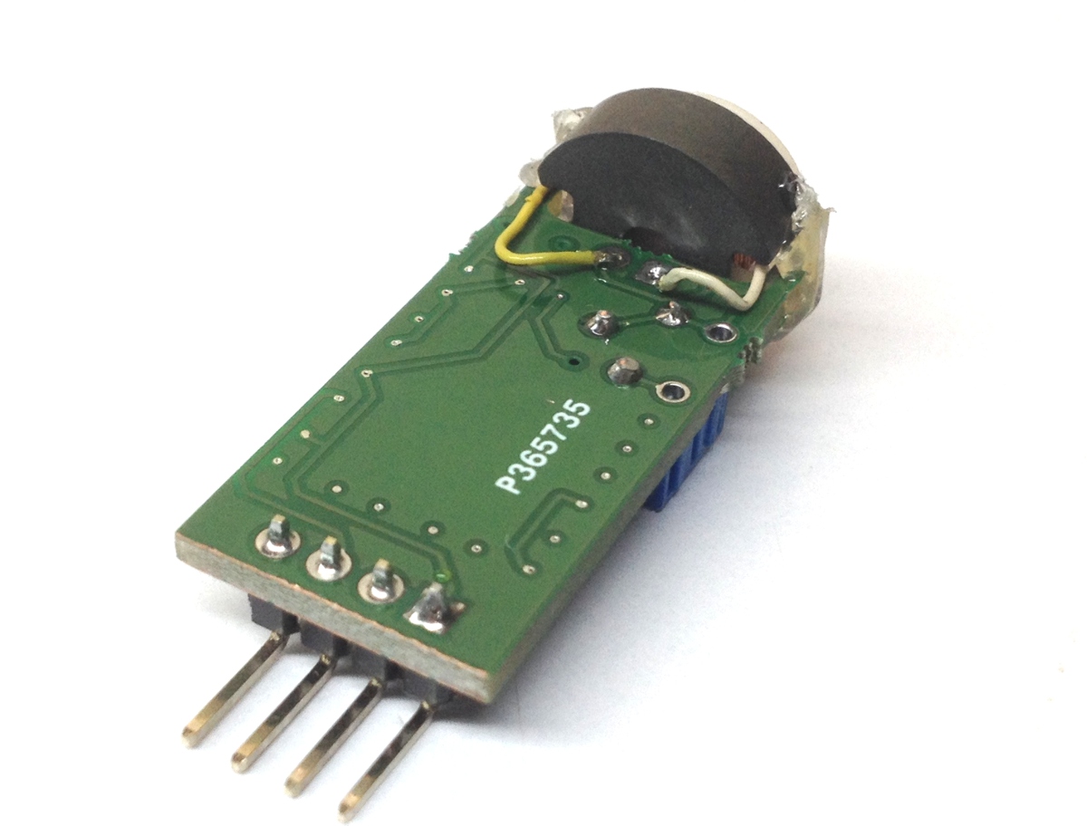
The circuit published here is an Inductive Proximity Sensor, which is used for non-contact detection of metallic objects. The circuit can be used for the detection of metal objects or as positioning sensor. The TCA505 is used to design inductive proximity switche which can detect metal object from 5-10mm range. The resonant circuit of the LC oscillator is implemented with an open half-pot ferrite and a capacitor in parallel (pin LC). If a metallic target is moved closer to the open side of the half-pot ferrite, energy is drawn from the resonant circuit and the amplitude of the oscillation is reduced accordingly. This change in amplitude is transmitted to a threshold switch by means of a demodulator and triggers the outputs. I have tested the circuit with 12V DC however the circuit can also work with higher supply voltage, up to 42V with few components values changes, refer to datasheet for more info. Normally D2 LED is on, when the coil detects the metal object D2-LED goes off and D1 LED turns on, so normally Out-2 provides low output and Out-1 provides High output when metal object detected. Q3 Output goes high and Q1 goes Low, both outputa are open collector. PR1 Trimmer potentiometer helps to adjust the sensor sensitivity distance. Output of each transistor can directly drive small relay as each output has capacity of handling 50mA of current.
The circuit published here is an Inductive Proximity Sensor, which is used for non-contact detection of metallic objects. The circuit can be used for the detection of metal objects or as a positioning sensor. The TCA505 is used to design an inductive proximity switch that can detect a metal object from 5-10mm range. The resonant circuit of the LC oscillator is implemented with an open half-pot ferrite and a capacitor in parallel (pin LC). If a metallic target is moved closer to the open side of the half-pot ferrite, energy is drawn from the resonant circuit and the amplitude of the oscillation is reduced accordingly. This change in amplitude is transmitted to a threshold switch by means of a demodulator and triggers the outputs. I have tested the circuit with 12V DC however the circuit can also work with higher supply voltage, up to 42V with few components values changes, refer to datasheet for more info. Normally D2 LED is on, when the coil detects the metal object D2-LED goes off and D1 LED turns on, so normally Out-2 provides the low output and Out-1 provides High output when the metal object detected. Q3 Output goes high and Q1 goes Low, both outputs are open collector. PR1 Trimmer potentiometer helps to adjust the sensor sensitivity distance. The output of each transistor can directly drive a small relay as each output has the capacity of handling 50mA of current.
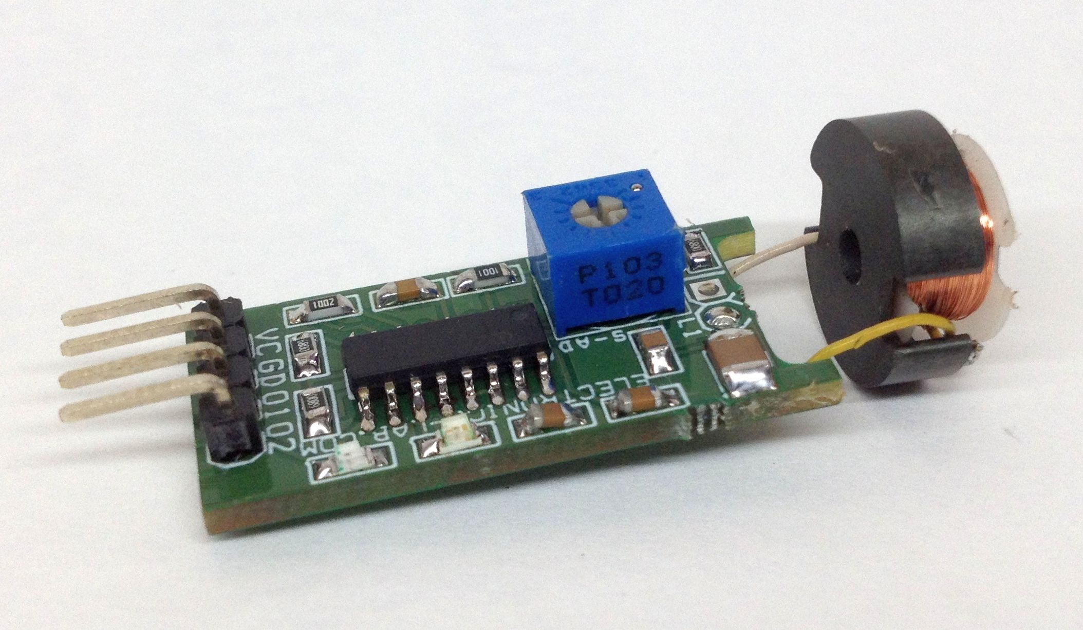
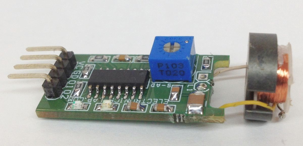
Note : Sensor Coil Can be made using half part of 14MM Pot iron Core, inductance has to be 540uH to 640uH
Features
Supply 12V DC
Dual Output (Both Open Collector)
Detection Range 5-10mm
Dual LED operation
D2-LED ON Normally Goes OFF When Sensor Detects the Object
D1-LED OFF Normally Goes ON When Sensor Detects the Object
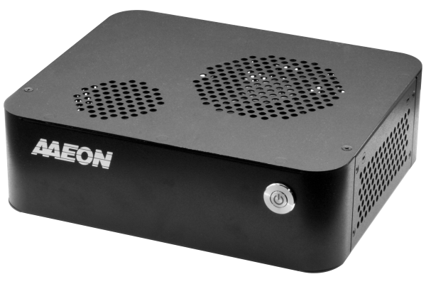
AAEON, an industry leader in embedded computing systems, announces the EPIC-KBS9-PUC barebones embedded system. Built upon our success and knowledge, the EPIC-KBS9-PUC offers the power of 6th and 7th Generation Intel Core Processors, four Gigabit Ethernet ports, and a range of expandability and customization to support your application.
The EPIC-KBS9-PUC is a barebones system based on our successful EPIC-KBS9 compact board. Customers have been using this compact EPIC board in a wide range of industrial applications including controlling automated warehouse robots, retail POS systems, and even a 3D printer for cakes. The EPIC-KBS9-PUC offers the power, flexibility and versatility of the EPIC-KBS9 board in a barebones system that is easy to integrate into a wide range of industrial application.
The EPIC-KBS9-PUC features a socket type supporting 6th and 7th Generation Intel Core desktop processors up to 65W. This means the EPIC-KBS9-PUC is one of the most powerful systems in its size. The board features dual channel 2133MHz DDR4 RAM supporting up to 32GB, providing the back-up needed to get the most out of your processor.
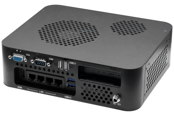
EPIC-KBS9-PUC rear view
The EPIC-KBS9-PUC is built to easily integrate into any embedded application. It features four Gigabit Ethernet ports designed for use with IP and PoE cameras, perfect for machine vision applications. It also offers two USB 3.0 and USB 2.0 ports in addition to a COM port. The EPIC-KBS9-PUC provides expandability with a full mSATA/mini-PCIe slot and a PCI express [x4] slot, allowing almost endless options, including graphics and frame grabber cards. The system can also be ordered with VESA or wall mount kits, allowing it to be easily installed anywhere.
As with all of our products, AAEON Manufacturer Services provides the ability to customize and configure the EPIC-KBS9-PUC to our customer’s needs. Configurations range from adding additional USB ports to offering HDMI 2.0 with 4K High Definition video output for customers needing an embedded system for digital signage or kiosks.
The EPIC-KBS9-PUC offers proven performance and features in a barebones chassis that is easy to setup for your embedded application. With the flexibility and support of AAEON Manufacturer Services, the EPIC-KBS9-PUC is the embedded barebones system with proven performance and flexibility.
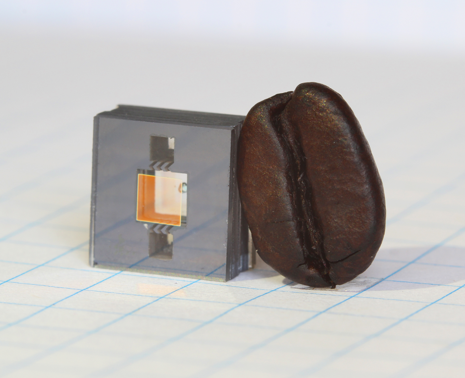
Physicists at the National Institute of Standards and Technology (NIST) and partners have demonstrated an experimental, next-generation atomic clock—ticking at high “optical” frequencies—that is much smaller than usual, made of just three small chips plus supporting electronics and optics.
Described in Optica, the chip-scale clock is based on the vibrations, or “ticks,” of rubidium atoms confined in a tiny glass container, called a vapor cell, on a chip. Two frequency combs on chips act like gears to link the atoms’ high-frequency optical ticks to a lower, widely used microwave frequency that can be used in applications.
The chip-based heart of the new clock requires very little power (just 275 milliwatts) and, with additional technology advances, could potentially be made small enough to be handheld. Chip-scale optical clocks like this could eventually replace traditional oscillators in applications such as navigation systems and telecommunications networks and serve as backup clocks on satellites.
We made an optical atomic clock in which all key components are microfabricated and work together to produce an exceptionally stable output,” NIST Fellow John Kitching said. “Ultimately, we expect this work to lead to small, low-power clocks that are exceptionally stable and will bring a new generation of accurate timing to portable, battery-operated devices.
The clock was built at NIST with help from the California Institute of Technology (Pasadena, Calif.), Stanford University (Stanford, Calif.) and Charles Stark Draper Laboratories (Cambridge, Mass.).
Espressif announces the release of the ESP32-S2 Secure Wi-Fi MCU, which is a highly integrated, low-power, 2.4 GHz Wi-Fi Microcontroller SoC supporting Wi-Fi HT40 and 43 GPIOs. Based on Xtensa® single-core 32-bit LX7 processor, ESP32-S2 can be clocked at up to 240 MHz.
ESP32-S2 is a highly integrated, low-power, 2.4 GHz Wi-Fi Microcontroller SoC supporting Wi-Fi HT40 and 43 GPIOs. Based on Xtensa® single-core 32-bit LX7 processor, it can be clocked at up to 240 MHz.
With state-of-the-art power management and RF performance, IO capabilities and security features, ESP32-S2 is an ideal choice for a wide variety of IoT or connectivity-based applications, including smart home and wearables. With an integrated 240 MHz Xtensa® core, ESP32-S2 is sufficient for building the most demanding connected devices without requiring external MCUs.
By leveraging Espressif’s mature and production-ready software development framework (ESP-IDF), ESP32-S2 achieves a balance of performance and cost, thus bringing faster and more secure IoT connectivity solutions to the market.
Features
CPU and Memory
Xtensa® single-core 32-bit LX7 microcontroller
7-stage pipeline
Clock frequency of up to 240 MHz
Ultra-low-power co-processor
320 kB SRAM, 128 kB ROM, 16 KB RTC memory
External SPIRAM (128 MB total) support
Up to 1 GB of external flash support
Separate instruction and data cache
Connectivity
Wi-Fi 802.11 b/g/n
1×1 transmit and receive
HT40 support with data rate up to 150 Mbps
Support for TCP/IP networking, ESP-MESH networking, TLS 1.0, 1.1 and 1.2 and other networking protocols over Wi-Fi
Support Time-of-Flight (TOF) measurements with normal Wi-Fi packets
IO Peripherals
43 programmable GPIOs
14 capacitive touch sensing IOs
Standard peripherals including SPI, I2C, I2S, UART, ADC/DAC and PWM
LCD (8-bit parallel RGB/8080/6800) interface and also support for 16/24-bit parallel
Camera interface supports 8 or 16-bit DVP image sensor, with clock frequency of up to 40 MHz
Full speed USB OTG support
Security
RSA-3072-based trusted application boot
AES256-XTS-based flash encryption to protect sensitive data at rest
4096-bit eFUSE memory with 2048 bits available for application
Digital signature peripheral for secure storage of private keys and generation of RSA signatures
Engineering Samples of ESP32-S2 beta will be available in June.
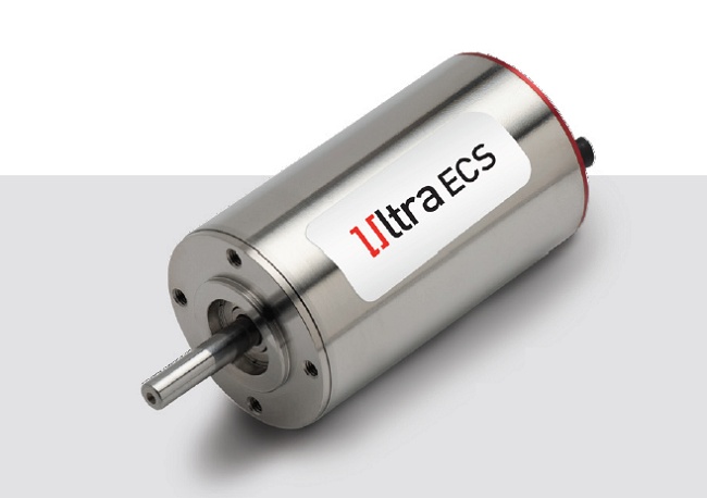
Portescap has expanded its Ultra EC range of brushless DC slotless motors with the introduction of a ultra-high speed 2 pole motor, the 35ECS.
The 35mm diameter slotless motor draws up to 330W max imum in continuous operation and sustains speeds up to 40,000 rpm. The new design comes in two lengths: the 35ECS60 at 60mm and the 35ECS80 at 80mm , with peak torque s during 2s up to 1.1Nm and 2.0Nm, respectively. Both motors feature the company’s pat ented Ultra EC coil technology which provides unparalleled torque and power density with limited core losses over a wide range of working speeds without friction and brush wear. The se motors feature a laser welded front flange to ensure the strongest housing to sustain high torque reaction. A temperature probe on the coil head ensures an optimized control of motor performances in heavy duty applications. The devices are offered with hall sensors and a total of 6 different coils to match your speed and voltage requirements. Upon request, Portescap can also provide options for customization including gearboxes, encoders, coil variations and mechanical interface modifications.
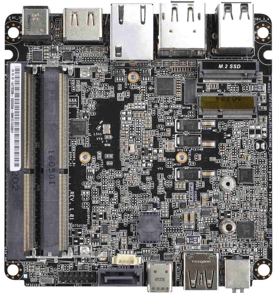
Populated with the Intel Core i5 7300U and i3 7100U processors, the WUX-7x00U is a small form factor (SFF) embedded board by Portwell. The processors, formerly codenamed Kaby Lake, integrate the low power Intel Gen. 9.5 HD Graphics, 620 graphics engine with 24 execution units, enabling enhanced 3D graphics performance and higher speed for 4K encode and decode operations.
The low power consumption makes the WUX-7x00U particularly suitable for applications such as medical equipment, IoT gateway, industrial automation, warehouse automation and digital signage.
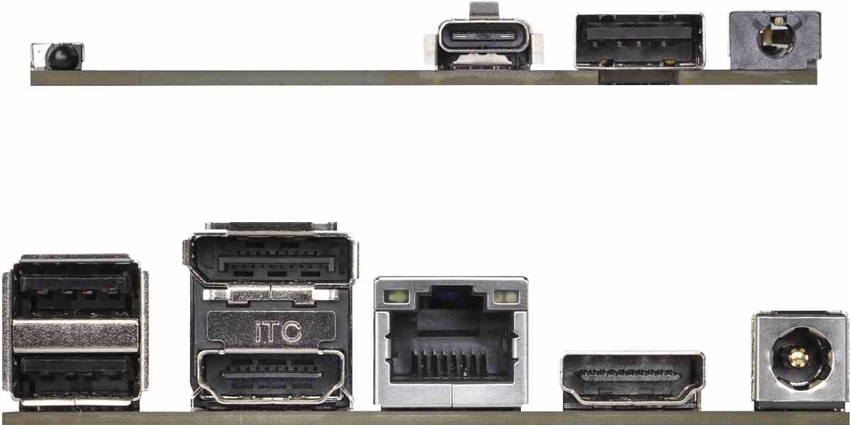
WUX-7x00U back view
The WUX-7x00U has a compact footprint of 101.6 x 101.6mm or four x four-inch. Within this compact area, it has up to 32Gbyte DDR4LSDRAM (2133MHz) RAM and multiple storage interfaces like one SATA III port and one M.2 Key M for SSD. There are also three USB 3.0 ports and one USB3.0 Type-C port. The Intel 620 HD graphics engine drives one DisplayPort (DP) (4096 x 2160) and two high definition multimedia interfaces (HDMI) with resolution up to 4096 x 2304, which can be operated simultaneously. An M.2 Key E interface, enables wi-fi and Bluetooth communication and connectivity for IoT applications.
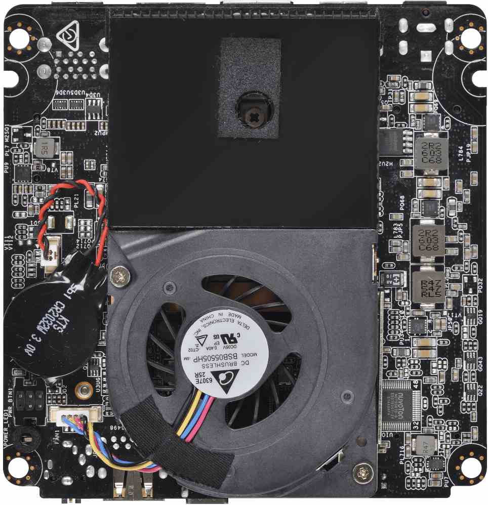
WUX-7x00U side views
The Portwell WUX-7x00U operates with thermal design power (TDP) of 15W. The integrated low-profile fan ensures long and stable operation. The wide voltage power input ranges from 12 to 19V. The design and multi-core processing power ensures that the Portwell WUX-7x00U embedded board can execute an array of applications that demand processing power as well as connectivity from digital signage in various environments, from manufacturing robots and industrial automation, through to video analytics-based appliances.
Portwell is an Associate member of the Intel Internet of Things Solutions Alliance, designs and manufactures a full range of IPC products (SBC, backplane, redundant power supply, rack mount and node chassis), embedded architecture solutions, DVR system platforms and communications appliances. Portwell provides R&D and project management services to reduce time to market, and lower project risk and cost.
Highligh Features
Intel® Kaby Lake-U Core i Processor
Up to 32GB DDR4 2133 non-ECC SDRAM on two SODIMM slots
Dual displays including DP and HDMI up to UHD resolution
2x M.2 (one E Key, one M Key) slots, 1x SATA III port
3 x USB 3.0, 1 x USB 3.0 (Type C), 1 x IR
Wide voltage DC power input from 12V ~19V
Portwell is an ISO 13485, ISO 9001 and ISO 14001-certified company that deploys quality assurance through product design, verification and manufacturing cycles.
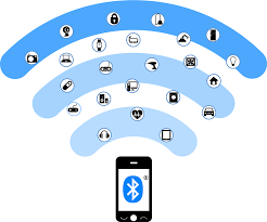
One of the most beautiful features which the ESP32 has over the ESP-12e is the fact that, asides the WiFi, it has two other communication modules onboard. The ESP32 comes with an onboard Classic Bluetooth and Bluetooth Low Energy modules. For today’s tutorial, we will explore how the Bluetooth Low Energy Module onboard the ESP-32 can be used in projects.
The Bluetooth protocol can be divided into two types; Classic Bluetooth, and the newer Bluetooth Low Energy protocol which is also referred to as Bluetooth 4.0. These two protocols operate within the 2.4ghz ISM band but they both have different data rate, different power consumption rate, and are optimized for different kind of applications. The Bluetooth Low Energy (BLE) was created to overcome the setbacks of classic Bluetooth which makes it a little bit unfit for use in IoT and battery powered smart devices which only need to send short burst of data at specific intervals. The BLE was designed to consume only a fraction of the power which classic Bluetooth devices consume when transmitting data and stay in sleep mode when not transmitting data unlike the Classic Bluetooth’s continuous data streaming. This makes BLE devices more power efficient and suitable for IoT products and other battery-powered smart devices which are usually desired to last for as long as possible on a single battery charge.
One of the most beautiful features which the ESP32 has over the ESP-12e is the fact that, asides the WiFi, it has two other communication modules onboard. The ESP32 comes with an onboard Classic Bluetooth and Bluetooth Low Energy modules. For today’s tutorial, we will explore how the Bluetooth Low Energy Module onboard the ESP-32 can be used in projects.
Introduction to Bluetooth Low Energy – BLE
The Bluetooth protocol can be divided into two types; Classic Bluetooth, and the newer Bluetooth Low Energy protocol which is also referred to as Bluetooth 4.0. These two protocols operate within the 2.4ghz ISM band but they both have different data rate, different power consumption rate, and are optimized for different kind of applications. The Bluetooth Low Energy (BLE) was created to overcome the setbacks of classic Bluetooth which makes it a little bit unfit for use in IoT and battery powered smart devices which only need to send short burst of data at specific intervals. The BLE was designed to consume only a fraction of the power which classic Bluetooth devices consume when transmitting data and stay in sleep mode when not transmitting data unlike the Classic Bluetooth’s continuous data streaming. This makes BLE devices more power efficient and suitable for IoT products and other battery-powered smart devices which are usually desired to last for as long as possible on a single battery charge.
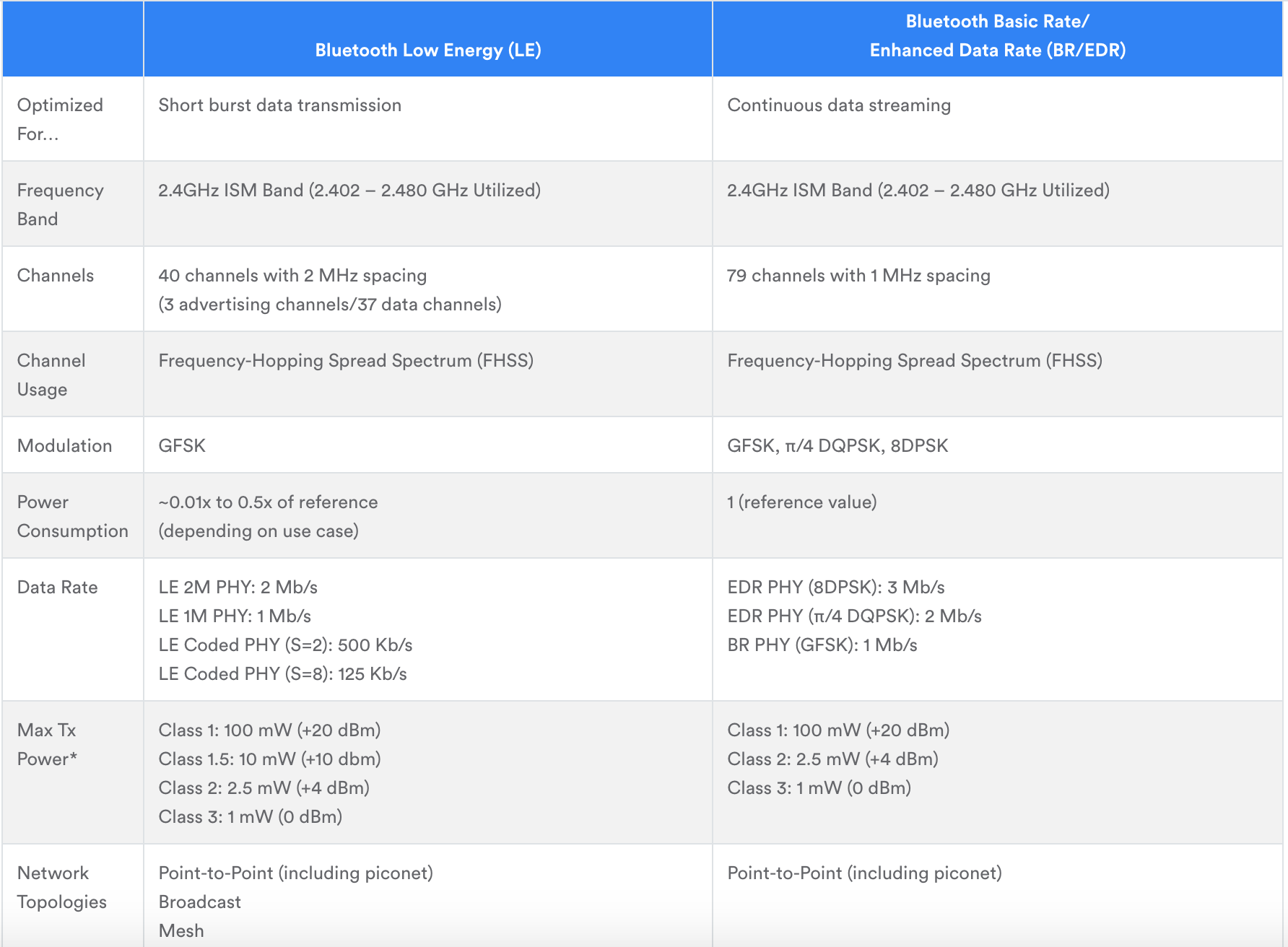
A detailed comparison between the two Bluetooth types is shown in the Image below.
BLE vs Classic Bluetooth
One of the downsides of the operation dynamics of BLE devices is the Complexity or Robustness (depending on how you look at it) of the messaging system. In classic Bluetooth, the serial port protocol (SPP) is usually used to send data between the devices as the communication occurs without much overhead, but for BLE, data during communication is organized using a profile referred to as GATT (Generic Attributes).
There are essentially two protocols that are important in communication between two BLE devices; GAP and GATT. Understanding how these two work is extremely important to programming devices to communicate via the BLE protocol.
GAP Protocol
GAP is an acronym for the Generic Access Profile, and it controls connections and advertising (Making a device visible and open for connection) in Bluetooth. It defines the roles which devices play in communication and also determines how the advertising (or scanning, depending on device role) payload is broadcasted.
There are essentially two roles which BLE devices can play based on GAP; Central Device and Peripheral Device. These two devices are the BLE’s representation for the more popular words; “Client” and “Server” respectively. The peripheral devices are usually small battery powered devices who broadcast the advertising data, waiting for a connection from a central device ready to receive the data payload. In IoT based solutions, the peripheral devices are usually sensors, etc., while the Central devices are usually gateway, smartphones, etc. Prior to connection, the Generic Access profile will keep broadcasting the advertising payload until there is a matching scanning response. Once a connection between a peripheral and a central device is established, the advertising process will stop and you will typically no longer be able to send advertising packets out anymore, at this point, GATT services and characteristics kick in to facilitate communication in both directions.
GATT Protocol
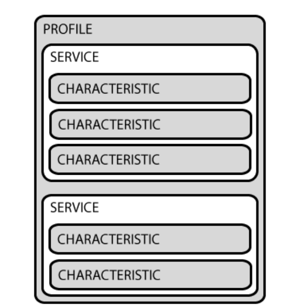
GATT is an acronym for the Generic Attribute Profile, and it defines how two Bluetooth Low Energy devices, transfer data back and forth between each other, using concepts called Services and Characteristics. It makes use of a generic data protocol called the Attribute Protocol (ATT), to store Services, Characteristics, and related data in a simple lookup table using 16-bit IDs for each entry in the table. The GATT hierarchical data structure comprises of three main elements; Profiles, Services, and Characteristics.
GATT
A Profile is a pre-defined collection of Services that has been compiled by either the Bluetooth SIG or by the peripheral designers. For example, in a heart rate monitor, a Heart Rate Profile could include the Heart Rate Service, the Battery Life Service, and the Device Information Service. A list of officially adopted GATT is available here.
Services are used to group data into logic entities and contain specific chunks of data called characteristics. A service can have one or more characteristics, and each service distinguishes itself from other services by means of a unique numeric ID called a UUID, which can be either 16-bit (for officially adopted BLE Services) or 128-bit (for custom services). A full list of officially adopted BLE services can be seen on the Services page of the Bluetooth Developer Portal. To better understand how services work, Consider the Heart Rate Example again, it could contain up to 3 characteristics which in the officially adopted service, for instance, includes; Heart Rate Measurement, Body Sensor Location, and Heart Rate Control Point. Thus a service essentially to group related data.
Characteristics represent the lowest level concept in GATT structure. It encapsulates a single data point and just like services, it distinguished from other characteristics using a Unique numeric ID; the UUID. Characteristics are the major containers that carry data between two devices.
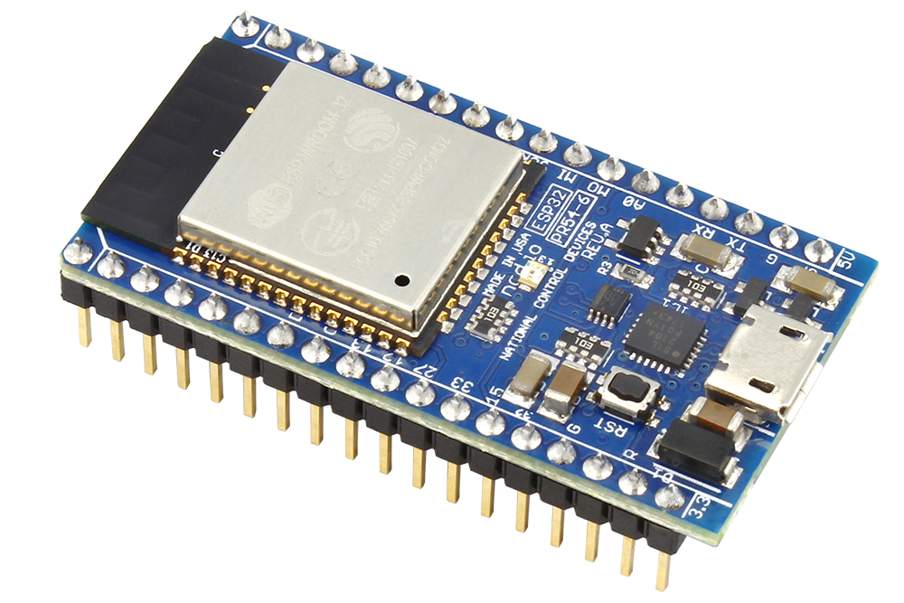
With these said, today’s tutorial will show how to set up the ESP32 as a Client (Central Device) and as Server (peripheral device). For proper demonstration, we will use two ESP32 boards. One of the boards will be programmed to act as the server, with characteristics to send random data, while the other ESP32 board will be programmed to act as a BLE scanner to find the server.
Required Components
DOIT ESP32 DevKit (2 nos)
Power Bank/ Battery
As mentioned in the introduction, we only need the ESP32 Module as it already has all that is needed for the project on board. The power bank helps to easily power the Devkit in standalone mode. You can easily modify this tutorial by adding sensors to send live data to the central device.
We will use just the ESP32 boards so with no schematics, we go straight to the project’s code.
Code
Since we will not connect any components, let’s jump straight to the code. As mentioned in the introduction, we will setup the ESP32 as a client and as a server. This means we need two different sketches and we will go over them one after the other.
It is important to note that the code for this project will be written using the Arduino IDE and it will be impossible to upload the code if your IDE does not have the ESP 32 Arduino board package installed. This setup, downloading and installing the ESP32 board files for Arduino was covered in our Introduction to ESP32 tutorial. Ensure you check it out.
Once you have the board files installed, it will automatically load several ESP 32 libraries to the Arduino IDE. Both sketches for today’s tutorial will be heavily dependent on one of those libraries; the ESP32 BLE Arduino Library. The library comprises of functions and declarations that make sending data through a complex protocol (at least more complex when compared with serial) like the BLE easy.
BLE Server Sketch
I will do a brief explanation of both sketches starting with the BLE Server. The algorithm for the BLE server follows the explanation during the introduction above. We start by creating a BLE Service, after which we create BLE Characteristics under that service and a BLE descriptor under the characteristics. We then Start the service and start advertising so the device is visible to Scanning BLE devices.
We start the sketch by importing libraries within the BLE Arduino library that are required for the code.
Next, We write the void setup() function. We start by initializing serial communication to be used for debugging purposes, after which we create an object of the BLEDevice class and set the object as a server.
void setup() {
Serial.begin(115200);
Serial.println("Starting BLE work!");
BLEDevice::init("Long name works now");
BLEServer *pServer = BLEDevice::createServer();
Next, we create a service for the server and a characteristic for the service, specifying the UUID in both cases. The characteristic properties (which in this case are READ and WRITE) were also specified.
Next, we set a value for the characteristics. As mentioned earlier, we will use a random value for this tutorial but this could be a sensor value, or any other information you wish to send to the client.
pCharacteristic->setValue("Hello World says Neil");
Finally, we start the service, setup parameters for advertising and start sending out advertising payload.
pService->start();
// BLEAdvertising *pAdvertising = pServer->getAdvertising(); // this still is working for backward compatibility
BLEAdvertising *pAdvertising = BLEDevice::getAdvertising();
pAdvertising->addServiceUUID(SERVICE_UUID);
pAdvertising->setScanResponse(true);
pAdvertising->setMinPreferred(0x06); // functions that help with iPhone connections issue
pAdvertising->setMinPreferred(0x12);
BLEDevice::startAdvertising();
For this demo, we will leave the loop section empty but you can choose to perform further tasks within it. You can go through all the examples under the BLE Arduino library to better understand.
void loop() {
// put your main code here, to run repeatedly:
}
The complete code for the server is available below and it is also attached under the download section at the end of the tutorial.
/*
Based on Neil Kolban example for IDF: https://github.com/nkolban/esp32-snippets/blob/master/cpp_utils/tests/BLE%20Tests/SampleServer.cpp
Ported to Arduino ESP32 by Evandro Copercini
*/
#include <BLEDevice.h>
#include <BLEUtils.h>
#include <BLEServer.h>
// See the following for generating UUIDs:
// https://www.uuidgenerator.net/
#define SERVICE_UUID        "4fafc201-1fb5-459e-8fcc-c5c9c331914b"
#define CHARACTERISTIC_UUID "beb5483e-36e1-4688-b7f5-ea07361b26a8"
void setup() {
Serial.begin(115200);
Serial.println("Starting BLE work!");

BLEDevice::init("Long name works now");
BLEServer *pServer = BLEDevice::createServer();
BLEService *pService = pServer->createService(SERVICE_UUID);
  BLECharacteristic *pCharacteristic = pService->createCharacteristic(
                                         CHARACTERISTIC_UUID,
                                         BLECharacteristic::PROPERTY_READ |
                                         BLECharacteristic::PROPERTY_WRITE
                                       );
pCharacteristic->setValue("Hello World says Neil");
pService->start();
// BLEAdvertising *pAdvertising = pServer->getAdvertising();  // this still is working for backward compatibility
BLEAdvertising *pAdvertising = BLEDevice::getAdvertising();
pAdvertising->addServiceUUID(SERVICE_UUID);
pAdvertising->setScanResponse(true);
pAdvertising->setMinPreferred(0x06);  // functions that help with iPhone connections issue
pAdvertising->setMinPreferred(0x12);
BLEDevice::startAdvertising();
Serial.println("Characteristic defined! Now you can read it in your phone!");
}
void loop() {
// put your main code here, to run repeatedly:
delay(2000);
}
BLE Scanner Sketch
The scanner sketch like the server sketch is available as an example in the ESP 32 BLE Arduino Library.
As usual, we start the sketch by including the required libraries.
Next, we indicate the interval between scan payload broadcasting and create an object of the BLEscan class.
int scanTime = 5; //In seconds
BLEScan* pBLEScan;
Next, we write the void setup() function. We start by initializing the serial monitor after which we initialize the BLE which automatically activates the BLE module on the ESP32. The argument is set as blank since we don’t really require a name for the device.
To round up the setup() function, we call the scan function, setting all the parameters required for the scan.
pBLEScan = BLEDevice::getScan(); //create new scan
pBLEScan->setAdvertisedDeviceCallbacks(new MyAdvertisedDeviceCallbacks());
pBLEScan->setActiveScan(true); //active scan uses more power, but get results faster
pBLEScan->setInterval(100);
pBLEScan->setWindow(99); // less or equal setInterval value
}
Next, we write the void loop() function. The algorithm behind the void loop() function is used to simply check if any device has been found and print those devices alongside their number. The results are cleared and the loop starts all over again.
void loop() {
// put your main code here, to run repeatedly:
BLEScanResults foundDevices = pBLEScan->start(scanTime, false);
Serial.print("Devices found: ");
Serial.println(foundDevices.getCount());
Serial.println("Scan done!");
pBLEScan->clearResults(); // delete results fromBLEScan buffer to release memory
delay(2000);
}
The complete code for the scanner is available below and also attached in the zip file under the download section.
/*
Based on Neil Kolban example for IDF: https://github.com/nkolban/esp32-snippets/blob/master/cpp_utils/tests/BLE%20Tests/SampleScan.cpp
Ported to Arduino ESP32 by Evandro Copercini
*/
#include <BLEDevice.h>
#include <BLEUtils.h>
#include <BLEScan.h>
#include <BLEAdvertisedDevice.h>
int scanTime = 5; //In seconds
BLEScan* pBLEScan;
class MyAdvertisedDeviceCallbacks: public BLEAdvertisedDeviceCallbacks {
void onResult(BLEAdvertisedDevice advertisedDevice) {
Serial.printf("Advertised Device: %s \n", advertisedDevice.toString().c_str());
}
};
void setup() {
  Serial.begin(115200);
  Serial.println("Scanning...");

  BLEDevice::init("");
pBLEScan = BLEDevice::getScan(); //create new scan
  pBLEScan->setAdvertisedDeviceCallbacks(new MyAdvertisedDeviceCallbacks());
  pBLEScan->setActiveScan(true); //active scan uses more power, but get results faster
  pBLEScan->setInterval(100);
  pBLEScan->setWindow(99);  // less or equal setInterval value
}
void loop() {
  // put your main code here, to run repeatedly:
  BLEScanResults foundDevices = pBLEScan->start(scanTime, false);
  Serial.print("Devices found: ");
  Serial.println(foundDevices.getCount());
  Serial.println("Scan done!");
  pBLEScan->clearResults();   // delete results fromBLEScan buffer to release memory
  delay(2000);
}
Demo
Copy the code and paste in the Arduino IDE (or launch the code from the example file), then one after the other upload the server sketch to the board designated as the server and the scanner code to the board designated as the scanner. For this demonstration to work, both boards need to be “ON” as the client will not be able to see the server if its “OFF”, so you can either leave the two of them connected to your PC or connect the Server to a power bank or any other power source. With that sorted, launch the serial monitor, ensuring it is set to the serial port to which the client is connected. After a few seconds, you should see the number of Bluetooth devices found and the name(s) displayed on the serial monitor.
That’s it for today’s tutorial. You can immediately expand the project by hooking up a sensor the BLE server and running the BLE Client example on the other ESP32 board or better still use a mobile app that supports BLE devices to interact with the server. BLE is currently one of the most widely used communication methods for smart devices and I hope this tutorial has given you information required to use it for your own project.
As usual, do feel free to reach out to me via the comment section with questions or general comments about the tutorial.