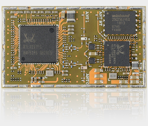
8devicesis accepting pre-orders for its $29 Komikan module, and sandwich-style $59 Komikan DVK development board for Wave2 prototyping at up to 1.166Gbps. The Komikan module runs OpenWrt on a MIPS24k-based Realtek SoC with dual-band, MU-MIMO 802.11ac. The Komikan has the ability to operate without a heatsink, as well as having a lower, 6W power consumption compared to other Wave2 modules. The Wave2 is the second, faster wave of 802.11ac (WiFi 5) radios with dual-band MU-MIMO technology for simultaneous WiFi connections to multiple devices.
The first 802.11ax (WiFi 6) radios will arrive later this year, which will enable lower latency and power consumption, improved synchronized data delivery, and up to 30 percent faster speed. It will be a while before computers, phones, and other devices support 802.11ax, as only a few devices support Wave2 now. The Komikan module runs OpenWrt on a 1GHz Realtek RTL819FS processor. The Komikan’s Wave 2 (concurrent 2.4GHz/5GHz 802.11 a/b/g/n/ac) capacity is the result of its Realtek RTL8822BEH chipset. The RTL8822BEH-VR chipset also enables the module’s Bluetooth 4.1 capability. The 37.5 x 21.3mm Komikan module utilizes an LGA form factor and is approximately half the size of the earlier Rambutan. The module ships with 128MB RAM and 32MB flash.
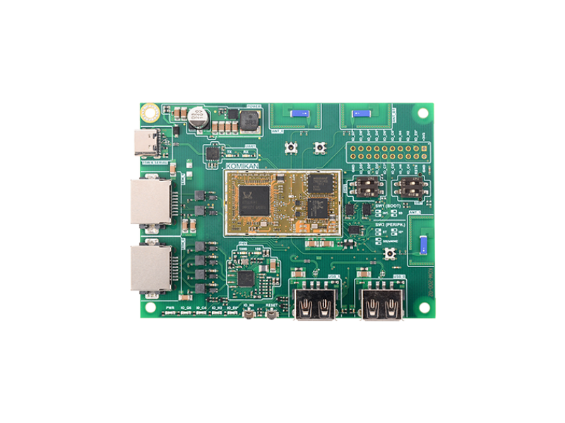
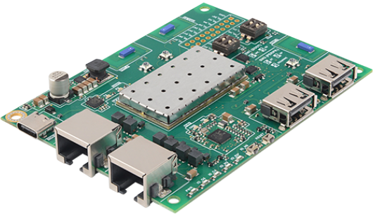
Komikan DVK
The Komikan module support 2x USB, 4x UART (1x for BT), RGMII, 2x SPI, PWM, MDIO, eMMC, JTAG, 2x I2S, PCM, 2x I2C, and P-NAND. The module also enables 44x GPIO pins, with several pins supporting an external antenna. Its 3.3V module outputs power at “22 dBm per chain.” The Komikan DVK board features an eMMC socket and a microSD slot, to expand the Komikan module’s memories.
The board offers both 10/100 and 10/100/1000Mbps (GbE) ports, a 2x USB 2.0 host ports, and a USB Type-C for power and UART console duty. The dev board is also equipped with dual 2.4GHz/5GHz WiFi antennas, a Bluetooth antenna, reset and GPIO buttons, and dip switches. Available also is a 20-pin GPIO header. The $29 Komikan module and $59 Komikan DVK are available for pre-orders with shipping starting from May 15.
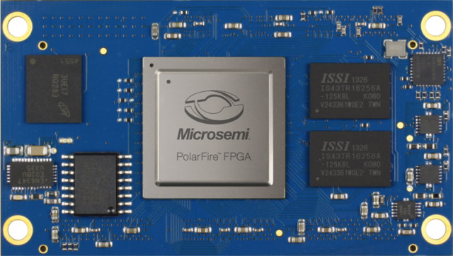
Specialist for embedded services and products, ARIES Embedded, will display the new M100PF System-on-Module (SoM) based on Microchip’s PolarFire FPGA family at embedded world 2019. At stand 441 in hall 3A ARIES Embedded will also introduce the complementary evaluation platform M100PFEVP, which delivers a fast and easy project start for customers.
Our new M100PF board provides the full flexibility of the popular FPGAs for demanding applications in industrial and medical technology,
stated Andreas Widder, Managing Director of ARIES Embedded.
PolarFire captivates with up to 50 percent lower power consumption than competing FPGAs, at mid-range densities with exceptional safety and reliability.
With the SoM, ARIES Embedded extends the FPGA functionality with RAM, Flash, Clocking and additional features.
For industrial use, the system-on-module allows an expanded temperature range, from zero to +70°C up to -40 to +85°C. On the ARIES SoM, the PolarFire FPGAs provide 100, 192, or 300k logic elements (LE) and feature 12.7G transceivers with up to 50% lower power consumption. The 256 Mbit configuration storage, the DDR3 RAM (512Mbit, one or two gigabit), as well as four to 64Gbit eMMC NAND Flash allow the development of complex high performance designs.
Further features of the 72x40mm small SoMs are: eight SerDes with 250Mbps to 12.5Gbps, two PCI express Gen2 end points/root port slots, rich user I/O, and two Samtec QSH-090-01-F-D-A board-to-board connectors.
ARIES Embedded provides the corresponding evaluation platform M100PFEVP to help facilitate a smooth and fast project start. It enables customers to evaluate the PolarFire FPGA, realise prototypes and even use the FPGA in series production. The evaluation board contains two gigabit Ethernet, USB, and four DSub9 interfaces for CAN, RS232, and others, in addition to Pmod and HSMC extension connectors and a microSD card slot.
The M100PFEVP starter kit includes the M100PVEVP baseboard, M100PF-1DB storage extensions, a seven inch touchscreen, and power supply.
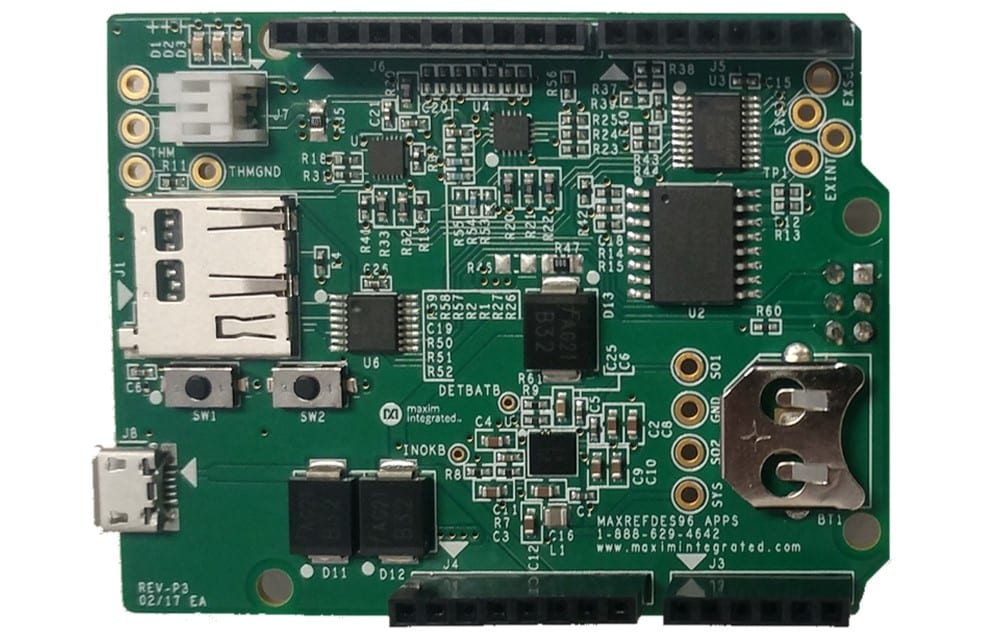
The MAXREFDES96# from Maxim Integrated Products is an Arduino Uno R3-compatible board that provides battery charge, boost, and data-logging capabilities. The board can be operated tethered to a power supply or computer to charge a battery and operate untethered to use the battery to power the Arduino board.
Typical applications are expected to include charger/fuel gauge evaluation and portable operation with data logging.
An SD card interface is provided to enable data logging up to 32GB of data. Status and battery state of charge (SOC) is displayed on three LEDs. An Arduino-compatible display can be added for more detailed data display.
The MAXREFDES96 includes the MAX77818 battery-management PMIC (charger only) and the MAX17201 ModelGauge m5 fuel gauge to demonstrate Maxim’s battery-management technology. The board comes on an Arduino Uno R3 platform. The MAX77818 boost circuit can power the Arduino and MAXREFDES96# while disconnected from a power supply.
Additionally, the included DS3231M RTC and a micro-SD card socket allow for data logging with timestamps. The MAX77818 automatically switches between charge mode and boost mode without host intervention to allow the board to switch from battery charging to boosted voltage; this allows the board to run in stand-alone battery-powered applications.
The MAXREFDES96# uses a variety of Maxim devices
The MAX77818 is used for its programmable charge capability and runs up to 3A with an appropriate supply. It can be programmed to automatically switch between charge mode and boost mode based on the presence of the input power. This allows a stand-alone application that switches between charging the battery and boosting the battery voltage to power the 5V rail, allowing it to function properly without intervention from a host.
The MAX17201 is used for its ModelGauge m5 EZ fuel-gauge capability, which allows a compatible chemistry battery to be used without characterizing it, reducing development time.
The MAX7315 I2C-controlled port expander is included to reduce the number of pins used on the Arduino interface. Because the MAX7315 uses the I2C to communicate with the host, the I/O pins that the switches and LEDs would otherwise use can be used for something else. The MAX7315 controls three LEDs for display and debounces two switches for program control.
The MAX7369 I2C mux is included for two reasons. The MAX77818 is both a charger and a fuel gauge, and its fuel-gauge I2C address is identical to the MAX17201. Therefore, when the MAX17201 is being addressed, it must be isolated from the MAX77818, and the MAX7369 provides that isolation. Secondly, the DS3231M RTC is used on other shields, so the address could conflict between the MAXREFDES96# DS3231M and one used on another board. The mux allows the on-board DS3231M to be deselected if needed. The DS3231M also allows its address to be changed by pin strapping, if desired. There is one port on the mux that is uncommitted, which could be used to try out another device such as a fuel gauge that has the same address as the other fuel gauges.
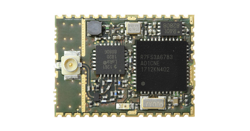
Renesas Synergy™ goes LoRa® with the new, tiny FMLR-61-U-RSS3 modules equipped with the latest software “LoRa Basics™ MAC” and now available at Avnet Silica.
Everybody wants to connect “things” to the “IoT” and LoRa® is the ultimate technology to do so across long distances (up to 50km LOS). The new, tiny FMLR-61-U-RSS3 module, designed by Miromico, comes with the latest software “LoRa Basics™ MAC” and is now available in early samples exclusively from Avnet Silica. Of course, it comes with the giant Synergy Software Package (SSP) to enable you to add your own functionality quickly.
The FMLR-61-U-RSS3 module is only 14.2mm x 19.5mm in size. Its operating voltage is 1.8V to 3.3V, and the module’s power consumption ranges from just 1.4uA in sleep mode to 25.5mA (typical) in TX mode (14dBm). Receiver sensitivity is -148dBm in LoRa mode [email protected] kHz, and the module’s operating temperature range is -40 to 85°C. The module’s exceptional specifications make it ideal for urban as well as rural sensing applications such as metering, asset tracking, building automation, security, wearables, predictive maintenance and more.
The FMLR-61-U-RSS3 module employs the S3A6 MCU with integrated 48 MHz Arm® Cortex®- M4 core, and features 256 KB code flash memory, 8 KB data flash, and 32 KB SRAM, which is enough memory to allow engineers to add a variety of their own functions. Most MCU signals are available at the module level to make them externally accessible. Manufactured in a low- power process, the S3A6 peripheral set includes analog features such as a 14-bit SAR analog- to-digital converter (ADC), 12-bit digital-to-analog converter (DAC), op amps, and comparators. Various timer channels and serial ports, USB function, CAN, DMA, and powerful safety and security hardware makes the S3A6 an ideal MCU for a wide range of battery-operated applications.
The Renesas Synergy Platform features the Synergy Software Package (SSP), which comprises a large selection of production-grade software. SSP includes the ThreadX® RTOS and lots of associated middleware such as a file system, USB stack, graphical user interface (GUI) software, application frameworks and functional libraries that can be used for encryption and DSP functions. This unique and powerful combination of hardware and software helps customers significantly accelerate their product development schedule.
Key benefits
Smallest certified LoRaWAN™ modules
Line-of-sight range of more than 50km
Runs customer specific applicatikons and proprietary radio stacks
A Beginner’s Guide to 3D Modeling ($24.95, 152 pp., on sale May 28, 2019) is the beginner’s guide to making precise 3D designs, from household objects and art to mechanical parts and even robots. Learn the principles of parametric modeling using Autodesk Fusion, the most powerful computer aided design (CAD) software, which is free for non-commercial use.
Engineers and mechanical designers use this and similar software to create parts to exact specifications. Written by 3D printing guru Cameron Coward, this practical guide’s hands-on tutorials walk readers through every step of its modeling projects. The book also shows readers how to make photorealistic renders of their models and draft technical drawings they can use to get parts professionally manufactured.
Learn the tools and design principles of the Fusion 360 3D modeling software
Build complex designs efficiently by breaking them down into parts
Master advanced modeling techniques to create coils, organic surfaces, and more
Author Cameron Coward is a writer, maker, mechanical designer, and drafter. He is a regular contributing author for Hackster.io and Hackaday.com and the author of Idiot’s Guides: 3D Printing.
“CAD has a steep learning curve that can be daunting to beginners,” said the author. “I created these tutorials so even someone with no experience can easily learn the skills to create their own designs and have them manufactured, or even print them out at home.”
day at the diverse types of projects that young people create using these cards!”
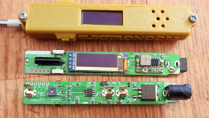
Portable soldering irons are recently getting popular among hobbyists, especially after the launch of the TS100 portable soldering iron. Although one can simply purchase a portable soldering iron from the many available options, hobbyists and DIY lovers would always enjoy making their own at home. Keeping this in mind, youtuber ElectroNoobs has recently launched a Kickstarter campaign for a DIY portable soldering iron kit. This $45 (Basic Kit) kit will contain everything you need to make your portable soldering iron, except the lipo battery which you have to buy yourself.
Crowdfunded DIY portable soldering iron kit
This DIY portable soldering iron has all the essential features that a good quality commercial soldering iron possesses. It features a 128*32 resolution OLED screen to display configuration settings and temperature. Two push buttons are mounted on both sides of the PCB for user interaction. On startup, one button is used to set configuration parameters and another one is for start heating. After heating starts, those buttons are used for increasing and decreasing the temperature. Pressing both of the buttons together puts the soldering iron in sleep mode and saves power.
Temperature can be set from 250ºC up to 480ºC. You can also configure the sleep time from OFF up to 10 minutes and the pre-set temperature which is the temperature that the iron reaches when powered on. The iron automatically enters sleep mode after a certain time of inactivity and it will automatically exit sleep mode when the iron is moved due to the onboard vibration sensor.
The temperature is measured using an OPAMP connected to the thermocouple of the T12 soldering iron tip. Then the microcontroller samples the voltage from the OPAMP using its ADC. To keep the iron tip at the specified temperature, a PID (Proportion Integration Derivation) loop runs on the MCU. PID is a robust and very popular control loop feedback mechanism. This will create a PWM signal and that signal drives the p-MOSFET to control the current through the heating element.
The DIY soldering iron kit comes in 3 different types: Basic Kit, Full Kit, and Premium Kit. Below are the details of each kit.
Basic Kit ($45):
1 x soldering iron PCB
1 x ATMEGA328p-AU chip
1 x T12 soldering iron tip
1 x 3D printed case
1 x all small components: res, cap, mosfet, display, connectors
Full Kit ($55):
1 x soldering iron PCB
1 x ATMEGA328p-AU chip
1 x T12 soldering iron tip
1 x 3D printed case
1 x LiPo power cable to DC plug
1 x FTDI programmer
1 x all small components: res, cap, mosfet, display, connectors
Premium Kit ($60):
2 x soldering iron PCB
2 x ATMEGA328p-AU chip
1 x T12 soldering iron tip
1 x 3D printed case
1 x FTDI programmer
1 x LiPo power cable to DC plug
1 x all small components: res, cap, mosfet, display, connectors
The backers of this campaign will also get a ZIP file with the PCB GERBERS, the full part list with buy links for each component, full guide, and code for the soldering iron. Also, there will be instruction videos coming soon so one can easily make the iron.
This Kickstarter campaign will help you to learn a lot of new things like the schematic and PCB design, manufacture, soldering SMD and through-hole components, burning bootloader, Arduino coding, PID control loop, etc. But, the only downside is its cost. By spending $5 more you could get a, also open source, TS100 which is a way better, and already proven product. So, let’s give time to this campaign, which focuses more on the learning aspect,to see if it becomes successful.
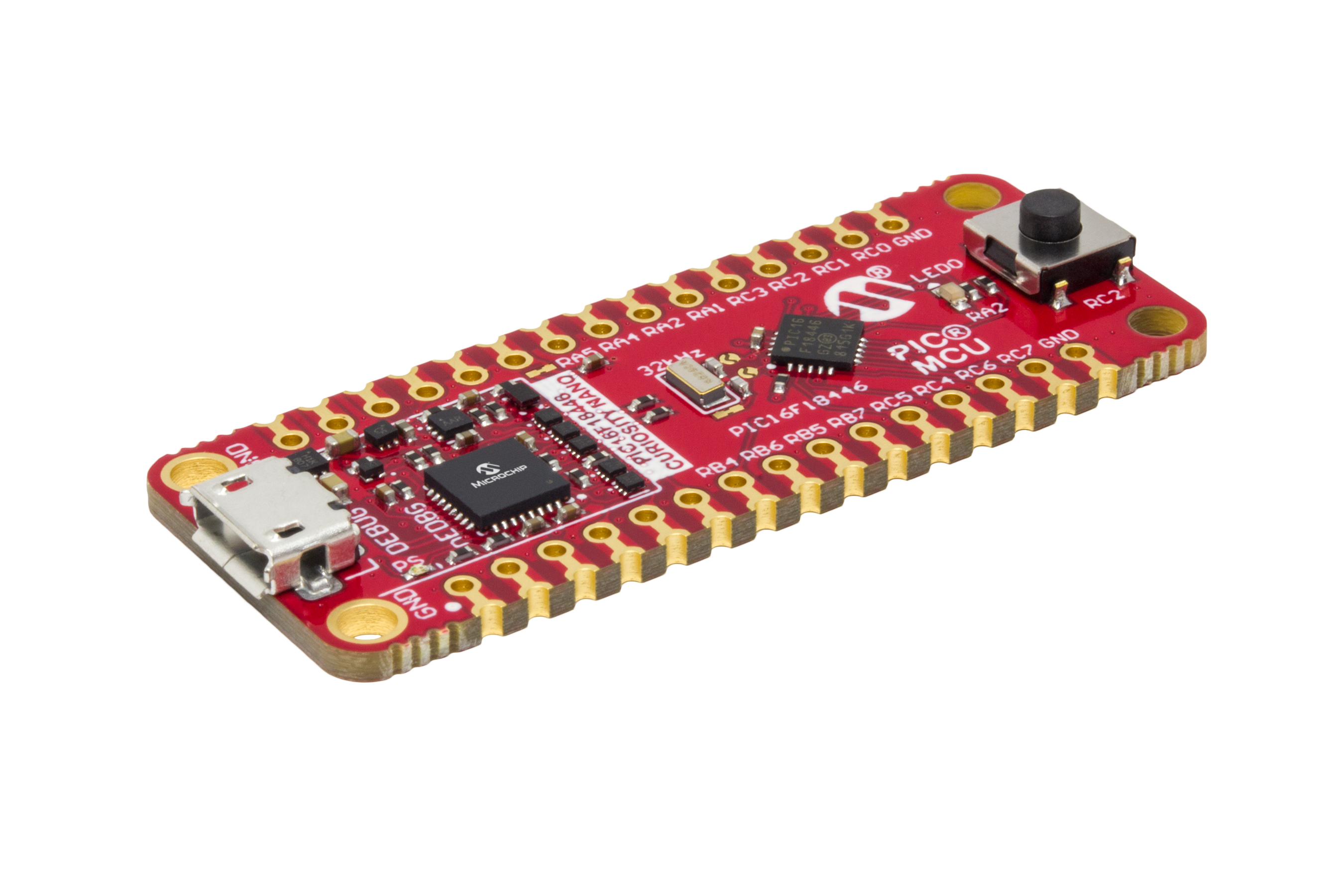
Microchip Technology DM164144 Curiosity Nano features full program and debug capabilities, and offers complete support for the next design. The kit provides access to the Intelligent analog and Core Independent Peripherals on the PIC16F18446. The kit features the award-winning MPLAB X integrated development platform and MPLAB Code Configurator (MCC). MCC is a free, graphical programming tool to configure the rich set of peripherals and functions specific for applications.
Features
PIC16F18446 microcontroller
One mechanical user switch
One yellow user LED
32.768kHz crystal for accurate timing and clock application, ~20ppm
On-board debugger
Board identification in Microchip MPLAB X
One green power and status LED
Programming and debugging
Virtual COM port (CDC)
One logic analyzer channel (DGI GPIO)
USB powered
Adjustable target voltage
MIC5353 LDO regulator controlled by the on-board debugger
2.3-5.1V output voltage (limited by USB input voltage)
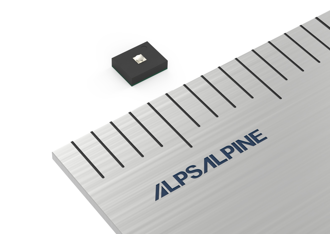
Alps Alpine Co., Ltd., a manufacturer of high-quality electronic products, has added the HSFPAR004A Force Sensor to its lineup. The sensor enhances impact resistance while maintaining the industry’s smallest size*1) and offers high linearity and high resolution, which makes it ideal for use in stylus pens and other input devices.
These days, electronic blackboards and tablets are being used on several occasions, such as school sessions and company meetings. Therefore, demand for pen-shaped devices (stylus pen), which are mostly used for the purpose of working creatively – including digital drawing and painting – has been growing. Stylus pens, or styli, contain force sensors that trace the trajectory of the pen tip and then reproduce different thicknesses in the artwork corresponding to the pressure applied. Styli require a sensor with high resolution and linearity, but also need to be sturdy enough to not break when the pen is unintentionally dropped.
The HSFPAR004A lives up to these requirements because it maintains the features of already existing products for high linearity (<2%FS), high resolution (detects micro force with less than 0.01 N), and small size of 2.00 mm × 1.60 mm × 0.66 mm (W×D×H), while at the same time realizing an improvement in impact resistance of up to 55 N. The sensor offers an operating life of 1,000,000 cycles and is resistant to external magnetic and electric fields. Besides its use in input devices, the sensor is suitable for industrial machines handling precision equipment and a range of diverse applications, especially on the grip parts of robot arms for precision grip force adjustments.
Key Features
High impact resistance proved by a breaking load of 55 N
Detects micro force of less than 0.01 N
Long operating life of more than 1 million cycles
Resistant to external magnetic fields and electric fields
The improved impact resistance of the sensor is achieved with the extension of the actuator diameter of the sensing zone*2) from the existing 0.20 mm to the new 0.40 mm, while at the same time keeping the rounded peripheral edge to disperse impacts. Therefore, the breakage risk of the sensor in stylus pens is reduced in case the pen is unintentionally dropped, while still guaranteeing smooth pen pressure expression without spoiling the easy integration into end products. Mass production has been underway since March.
*1 According to Alps Alpine Research, March 2019
*2 Tip of a sensor receiving stress (also called knob)
Demo Video
Additional Resources
Find more detailed technical data about the HSFPAR series on our product page
To the ire of many, manufacturing in small quantities have often led to sky high prices, hindering many makers from translating their ideas to reality. Now, to eliminate cost barriers and enable even more makers to experience the flexibility and convenience of turnkey PCB fabrication and assembly, Seeed Fusion is waiving off the assembly costs for the Seeed Fusion One-stop PCB Assembly (PCBA) service for five pieces.
When assembling a device on their own, makers have to go through the process of sourcing for components, creating homemade PCBs, and soldering each component by hand. Very often, unexpected problems arise. Delays begin to mount and this leads to slow delivery of products and missed launch dates.
Since the beginning of Seeed Studio, the Seeed Fusion PCBA Service has always had the goal of helping makers around the world skip the hassle of turning Gerbers and BOMs into the complete physical device. It enables rapid prototyping at affordable prices, and has since developed into the cornerstone of the Seeed Fusion service.
Parts can be sourced from major Global distributors such as Digikey, Mouser and others. But since Seeed is located in Shenzhen, the product innovation and electronics manufacturing juggernaut, Seeed’s close proximity to electronic component suppliers enables it to rapidly source the necessary components from local distributors, reducing the lead time to just 7 working days if all components are sourced locally from the Seeed Open Parts Library, which has swelled to more than 15,000 locally available parts. To begin the ordering process, customers are required to upload their PCB Gerber files and BOM files onto the online order webpage, and a complete quote will be generated in seconds. As part of Seeed’s efforts to make the Fusion PCBA service affordable, all PCBA orders are entitled to free express shipping to anywhere in the world.
Now, Seeed is going further by slashing the assembly, operation and set-up costs for orders up to 5 pieces of PCBA. This means that customers only need to pay for the materials and components needed, and Seeed Fusion will assemble the boards free of charge. Most orders will be able to enjoy cost savings of about 80% of the usual price. For example, assembling 5 Seeeduino boards would usually cost over $400. However, this offer would reduce the price tag to a mere $50.
With the Free Assembly for 5 PCBs offer, along with its previous Seeed Fusion promotions, Seeed is demonstrating that cost need not be a stumbling block when it comes to electronics projects. To those new to the Seeed Fusion PCBA service, this offer also presents a great opportunity to try it out. Navigate to the dedicated offer page to experience the convenience of Seeed’s Fusion PCBA service. The offer is only available once per customer.
One of the most interesting project we can build while learning to work with a WiFi Based board is a web Server. As we continue the journey to learn how to build projects with the ESP32, we will examine how to build a simple web Server with the ESP32.
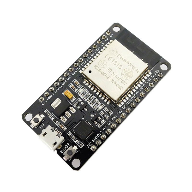
DOIT ESP32 DevKit
A Web server is essentially a device which stores, processes and delivers web pages to web clients, which can range from browsers on our laptops to Mobile apps on our smartphones. The communication between client and server takes place using a special protocol called Hypertext Transfer Protocol (HTTP). The client uses an URL to make a request for a particular page and the server responds with the content of that web page or an error message if the page is not available.
In our case, rather than responding with a specific webpage, the URL will be used to control the state of LEDs connected to the ESP and the changes made will be updated on the webpage. For instance, if a URL like “http://192.168.1.1/ledon” is entered in the browser, the web server will understand its time to turn the LED “ON” and then update the status of the LED to “ON” on the webpage. Same thing will happen when it’s required to go “OFF”.
At the end of today’s tutorial, you would know how to set up a web server on the ESP32 and connect to it via a client (Webpage) to control its GPIO pins.
Required Components
The following components are required for this project:
DOIT ESP32 DEVKIT V1
220 ohms Resistor (2)
LED (2)
Breadboard
Jumper Wire
The DOIT Devkit V1 ESP32 board is used for this tutorial due to its obvious popularity among makers. Feel free to use any of the other ESP32 based boards for the project.
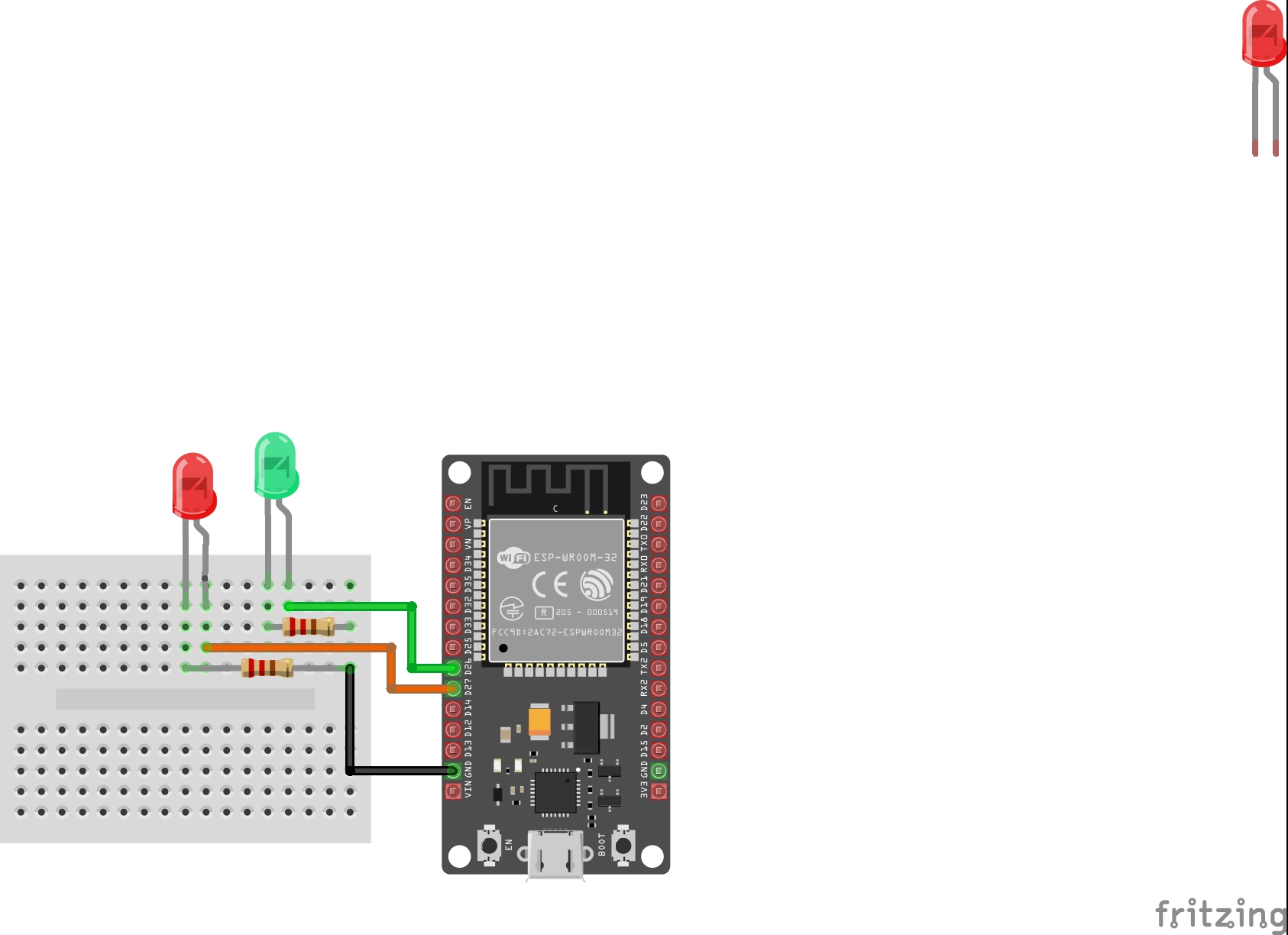
Schematics
The schematics for this tutorial is quite simple. As mentioned earlier, we will toggle LEDs to demonstrate what can be achieved using the NodeMCU Web server and while LEDs are being used here, you can decide to use more useful components like a relay, which could give you the ability to remotely control appliances in your home. Connect the components as shown below.
Schematics
The positive legs of the green and red LEDs are connected t0 GPIO pins 26 and 27 on the ESP32 (respectively), while their negative legs are connected to ground via a 220 ohms resistor to limit the amount of current flowing through the LEDs.
With the schematics done, we can now move to the code for the project.
Code
We will use the Arduino IDE to develop the sketch for today’s project due to its versatility, huge support, and popularity. To be able to do this, you need to install the ESP32 board support files on the Arduino IDE. We covered this in the ESP32 introduction tutorial that was published a few weeks back, so be sure to check it out.
The sketch for this tutorial is fairly easy. The algorithm involves us connecting the ESP32 to an access point and generating an IP address through which devices connected to the ESP can access the web server. The client (a webpage running on connected devices), in connection to the server, is serving a webpage that has buttons to control the LEDs and a function is placed behind the buttons to handle the actions that occur when they are clicked.
To reduce the amount of code we need to write, we will use the ESP32 WiFi Library. The library contains functions that make setting up the ESP32 as a web server easy. The library, along with several others, is packaged together with the ESP32 board files and are automatically installed when the ESP32 board files are installed on the Arduino IDE.
The code is an adaptation of the code for a similar Project by Rui Santos and an old ESP8266 webserver tutorial we wrote. You can check that out for better understanding.
To do a brief explanation, we start as usual, by including the library required for the project, which in this case, is just the WiFi.h library.
#include <WiFi.h>
Next, add the credentials of the WiFi access point to which the ESP32 will be connected. Ensure the username and password are in-between the double quotes. We also specify the port through which the system will communicate and create a variable to hold requests.
// Replace with your network credentials
const char* ssid     = "Enter_SSID_here";
const char* password = "Enter_Password_here";

// Set web server port number to 80
WiFiServer server(80);

// Variable to store the HTTP request
String header;
Next, we declare the pins of the ESP32 to which the red and green LED are connected and create variables to hold the state of the LEDs.
int greenled = 26;
int redled = 27;

String greenstate = "off";// state of green LED
String redstate = "off";// state of red LED
With this done, we move to the void setup() function.
We start by initializing the serial monitor (it will be used for debugging later) and set the pinModes of the pins to which the LEDs are connected as outputs. We then set the pins “LOW” to ensure the system starts at a neutral state.
void setup() {
  Serial.begin(115200);
 // Set the pinmode of the pins to which the LEDs are connected and turn them low to prevent flunctuations
  pinMode(greenled, OUTPUT);
  pinMode(redled, OUTPUT);
  digitalWrite(greenled, LOW);
  digitalWrite(redled, LOW);
Next, we connect to the access point using the credentials as arguments to the WiFi.begin() function and the WiFi.status() function to check if connection was successful.
WiFi.begin(ssid, password);
Serial.print("Connecting to ");
Serial.println(ssid);
while (WiFi.status() != WL_CONNECTED) {
  delay(500);
  Serial.print(".");
}
If the connection is successful, a text is printed on the serial monitor to indicate that, and the IP address of the web server is also displayed. This IP address becomes the web address for the server and it is what we need to enter on any web browser on the same network to access the Server.
Serial.println("");
Serial.println("WiFi connected.");
Serial.println("IP address: ");
Serial.println(WiFi.localIP());// this will display the Ip address of the Pi which should be entered into your browser
With that done, we start the server using the server.begin() function and proceed to the void loop( ) function.
server.begin();
The void loop() function is where the majority of the work is done. We start by using the server.available() function to listen for incoming connection by clients. When a client is available and connected, we read the client request and send a header as a response.
WiFiClient client = server.available();   // Listen for incoming clients

  if (client) {                             // If a new client connects,
    String currentLine = "";                // make a String to hold incoming data from the client
    while (client.connected()) {            // loop while the client's connected
      if (client.available()) {             // if there's bytes to read from the client,
        char c = client.read();             // read a byte, then
        Serial.write(c);                    // print it out the serial monitor
        header += c;
        if (c == '\n') {                    // if the byte is a newline character
          // if the current line is blank, you got two newline characters in a row.
          // that's the end of the client HTTP request, so send a response:
          if (currentLine.length() == 0) {
            // HTTP headers always start with a response code (e.g. HTTP/1.1 200 OK)
            // and a content-type so the client knows what's coming, then a blank line:
            client.println("HTTP/1.1 200 OK");
            client.println("Content-type:text/html");
            client.println("Connection: close");
            client.println();
Next, we check if the client’s request indicates a button press to turn any of the pins “ON/OFF” starting with the green LED. If the request indicates “ON”, the pin is turned high and the state variable is updated accordingly and vice versa.
// turns the GPIOs on and off
           if (header.indexOf("GET /green/on") >= 0) {
             Serial.println("green on");
             greenstate = "on";
             digitalWrite(greenled, HIGH);
           } else if (header.indexOf("GET /green/off") >= 0) {
             Serial.println("green off");
             greenstate = "off";
             digitalWrite(greenled, LOW);
           } else if (header.indexOf("GET /red/on") >= 0) {
             Serial.println("red on");
             redstate = "on";
             digitalWrite(redled, HIGH);
           } else if (header.indexOf("GET /red/off") >= 0) {
             Serial.println("red off");
             redstate = "off";
             digitalWrite(redled, LOW);
           }
Next, we create the webpage that will be displayed and updated by the NodeMCU as the user interacts with it. The key function for this is the Client.println() function which is used to send HTML scripts line by line to the client (browser).
We start by using the “doctype” to indicate that the next few texts to be printed are HTML lines.
client.println("<!DOCTYPE html><html>");
Next, we add the lines below to make webpage responsive irrespective of the browser being used.
Next, the webpage header is sent alongside the buttons which are set to display ON or OFF based on the current state of the LEDs. It will display OFF if the current state is ON and vice versa.
client.println("<body><h1>ESP32 Web Server</h1>");
// Display current state, and ON/OFF buttons for green LED
client.println("<p>green - State " + greenstate + "</p>");
// If the green LED is off, it displays the ON button
if (greenstate == "off") {
client.println("<p><a href=\"/green/on\"><button class=\"button\">ON</button></a></p>");
} else {
client.println("<p><a href=\"/green/off\"><button class=\"button button2\">OFF</button></a></p>");
}
// Display current state, and ON/OFF buttons for Red LED
client.println("<p>red - State " + redstate + "</p>");
// If the red LED is off, it displays the ON button
if (redstate == "off") {
client.println("<p><a href=\"/red/on\"><button class=\"button\">ON</button></a></p>");
} else {
client.println("<p><a href=\"/red/off\"><button class=\"button button2\">OFF</button></a></p>");
}
client.println("</body></html>");
Next, we close the connection and the loop goes over again.
// Clear the header variable
header = "";
// Close the connection
client.stop();
Serial.println("Client disconnected.");
Serial.println("");
The complete code for the project is available below and under the download section of this tutorial.
#include <WiFi.h>
// Replace with your network credentials
const char* ssid = "Enter_SSID_here";
const char* password = "Enter_Password_here";
// Set web server port number to 80
WiFiServer server(80);
// Variable to store the HTTP request String header;
String header;
// Declare the pins to which the LEDs are connected
int greenled = 26;
int redled = 27;
String greenstate = "off";// state of green LED
String redstate = "off";// state of red LED
void setup() {
Serial.begin(115200);
// Set the pinmode of the pins to which the LEDs are connected and turn them low to prevent flunctuations
pinMode(greenled, OUTPUT);
pinMode(redled, OUTPUT);
digitalWrite(greenled, LOW);
digitalWrite(redled, LOW);
//connect to access point
WiFi.begin(ssid, password);
Serial.print("Connecting to ");
Serial.println(ssid);
while (WiFi.status() != WL_CONNECTED) {
delay(500);
Serial.print(".");
}
// Print local IP address and start web server
Serial.println("");
Serial.println("WiFi connected.");
Serial.println("IP address: ");
Serial.println(WiFi.localIP());// this will display the Ip address of the Pi which should be entered into your browser
server.begin();
}
void loop(){
WiFiClient client = server.available(); // Listen for incoming clients
if (client) { // If a new client connects,
String currentLine = ""; // make a String to hold incoming data from the client
while (client.connected()) { // loop while the client's connected
if (client.available()) { // if there's bytes to read from the client,
char c = client.read(); // read a byte, then
Serial.write(c); // print it out the serial monitor
header += c;
if (c == '\n') { // if the byte is a newline character
// if the current line is blank, you got two newline characters in a row.
// that's the end of the client HTTP request, so send a response:
if (currentLine.length() == 0) {
// HTTP headers always start with a response code (e.g. HTTP/1.1 200 OK)
// and a content-type so the client knows what's coming, then a blank line:
client.println("HTTP/1.1 200 OK");
client.println("Content-type:text/html");
client.println("Connection: close");
client.println();
// turns the GPIOs on and off
if (header.indexOf("GET /green/on") >= 0) {
Serial.println("green on");
greenstate = "on";
digitalWrite(greenled, HIGH);
} else if (header.indexOf("GET /green/off") >= 0) {
Serial.println("green off");
greenstate = "off";
digitalWrite(greenled, LOW);
} else if (header.indexOf("GET /red/on") >= 0) {
Serial.println("red on");
redstate = "on";
digitalWrite(redled, HIGH);
} else if (header.indexOf("GET /red/off") >= 0) {
Serial.println("red off");
redstate = "off";
digitalWrite(redled, LOW);
}
// Display the HTML web page
client.println("<!DOCTYPE html><html>");
client.println("<head><meta name=\"viewport\" content=\"width=device-width, initial-scale=1\">");
client.println("<link rel=\"icon\" href=\"data:,\">");
// CSS to style the on/off buttons
// Feel free to change the background-color and font-size attributes to fit your preferences
client.println("<style>html { font-family: Helvetica; display: inline-block; margin: 0px auto; text-align: center;}");
client.println(".button { background-color: #195B6A; border: none; color: white; padding: 16px 40px;");
client.println("text-decoration: none; font-size: 30px; margin: 2px; cursor: pointer;}");
client.println(".button2 {background-color: #77878A;}</style></head>");
// Web Page Heading
client.println("<body><h1>ESP8266 Web Server</h1>");
// Display current state, and ON/OFF buttons for GPIO 26
client.println("<p>green - State " + greenstate + "</p>");
// If the green LED is off, it displays the ON button
if (greenstate == "off") {
client.println("<p><a href=\"/green/on\"><button class=\"button\">ON</button></a></p>");
} else {
client.println("<p><a href=\"/green/off\"><button class=\"button button2\">OFF</button></a></p>");
}
// Display current state, and ON/OFF buttons for GPIO 27
client.println("<p>red - State " + redstate + "</p>");
// If the red LED is off, it displays the ON button
if (redstate == "off") {
client.println("<p><a href=\"/red/on\"><button class=\"button\">ON</button></a></p>");
} else {
client.println("<p><a href=\"/red/off\"><button class=\"button button2\">OFF</button></a></p>");
}
client.println("</body></html>");
// The HTTP response ends with another blank line
client.println();
// Break out of the while loop
break;
} else { // if you got a newline, then clear currentLine
currentLine = "";
}
} else if (c != '\r') { // if you got anything else but a carriage return character,
currentLine += c; // add it to the end of the currentLine
}
}
}
// Clear the header variable
header = "";
// Close the connection
client.stop();
Serial.println("Client disconnected.");
Serial.println("");
}
}
Demo
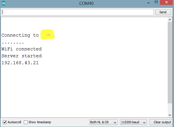
Connect the DOIT ESP32 Devkit to your computer, ensure it is selected as the board type on the Arduino IDE, then paste the code in the IDE, verify and upload. When the upload is finished open the serial monitor. You should see the IP address displayed as shown in the Image below.
IP Address
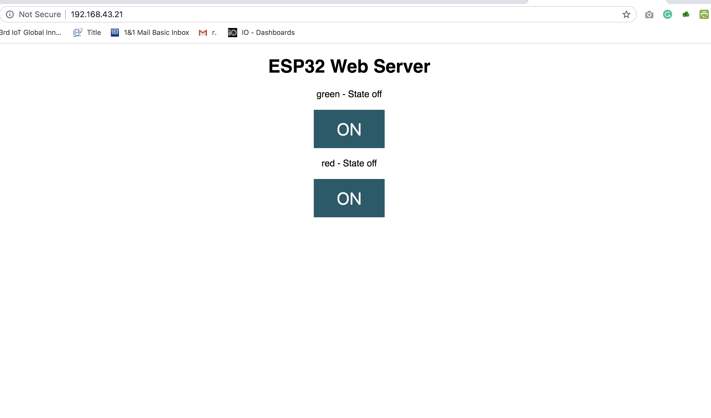
Connect a device (mobile phone or PC) to the same network as the ESP32, then open a web browser on that device and enter the IP address from the serial monitor in the Address bar. It should open the webpage we created on the web server as shown in the Image below. Click on the buttons to toggle the LEDs.
Webpage served to client
As mentioned earlier, in place of the LEDs, relays or any other kind of actuator could be connected to make the project more useful. Feel free to reach out to me via the comment section if you have any question on the tutorials.