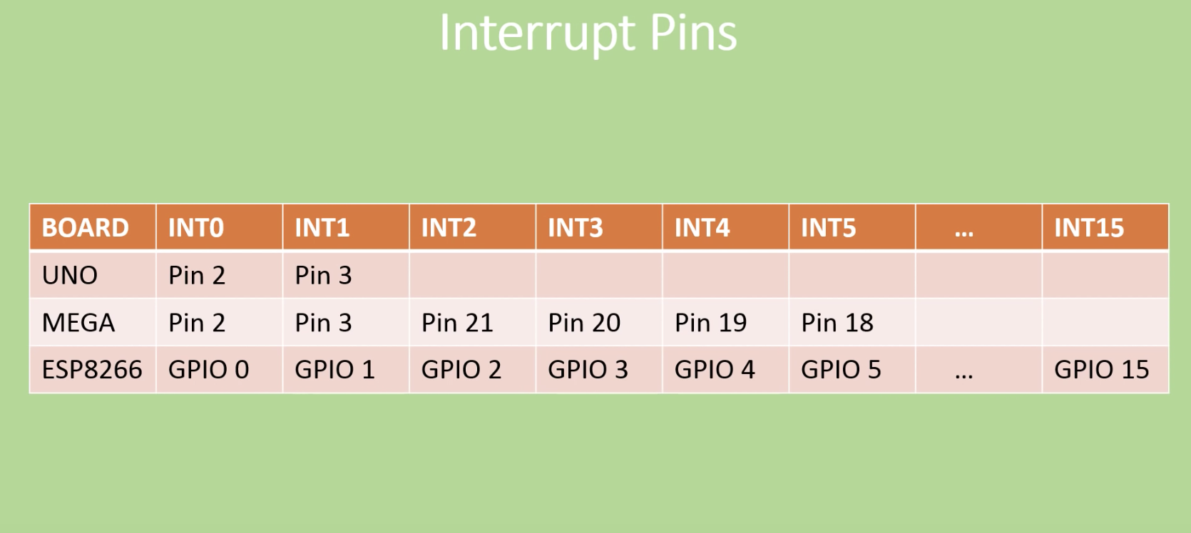
We can say that an Interrupt is an automatic transfer of software execution in response to a hardware event that is asynchronous with the current software execution. As it’s name says, interrupts, “interrupt” the normal program flow to perform an action (run another code block, function, etc.) and return back to the normal program flow when the action is completed. Interrupts can be established for events such as a counter’s number change, a pin changing state (from low to high or high to low), serial communication receiving information, or the Analog to Digital having established a conversion, etc., depending on what is supported by the microcontroller you are working with. For today’s tutorial, we will focus on interrupts as a result of pins changing state and how these can be used on the Arduino.
To monitor their digital pins for changes, microcontrollers by default use a technique generally referred to as “polling“, which means they constantly check the digital pins to know if any change has occurred. This usually takes a lot of the microcontroller’s resources and reduces its response time which may not be a problem in most applications but could be important in time-critical ones. One of the solutions usually adopted in scenarios where all the negatives of polling need to be eradicated is the use of external Interrupts. Interrupts provide the microcontrollers with a way of multitasking such that a particular digital pin does not need to be continually polled, as the pin would by itself signal the microcontroller and immediately pause the operations when a change occurs. Asides in time-critical applications, where the microcontroller needs increased response rate, Interrupts are widely used in power saving applications for all kind of device, from smartphones and their power button to your PC and the spacebar and the application goes on.
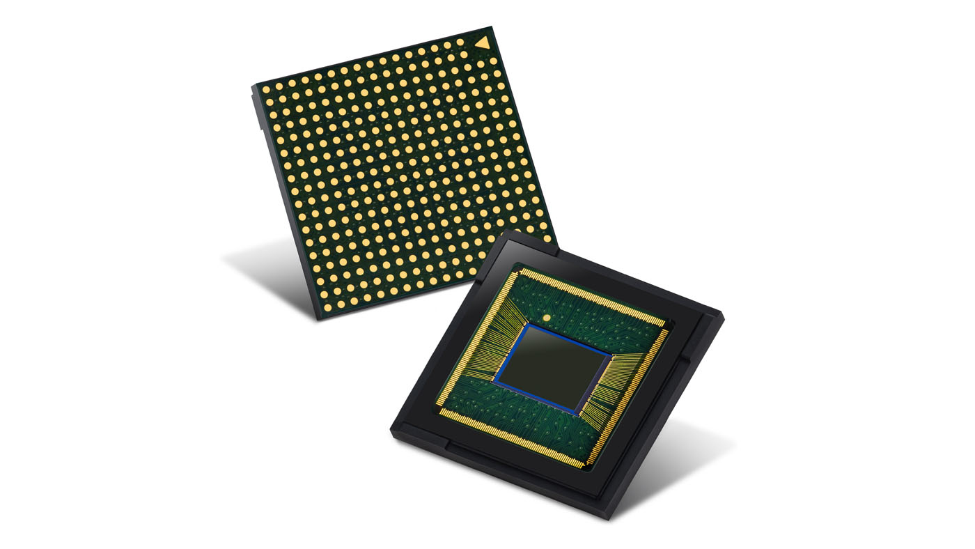
Samsung has expanded its 0.8μm pixel image sensor lineup with the 64-megapixel Isocell Bright GW1 and the 48Mp Isocell Bright GM2.
Isocell Bright GW1 is a 64Mp image sensor that features the highest resolution in Samsung’s 0.8μm-pixel image sensor lineup. With pixel-merging Tetracell technology and remosaic algorithm, GW1 can produce bright 16Mp images in low-light environments and highly-detailed 64Mp shots in brighter settings. To take pictures resembling the way the human eye perceives its surroundings in a mixed light environment, GW1 supports real-time high dynamic range (HDR) of up to 100-decibels (dB) that provides richer hues. In comparison, the dynamic range of a conventional image sensor is at around 60dB, while that of the human eye is typically considered to be around 120dB.
GW1 is equipped with a Dual Conversion Gain (DCG) that converts the received light into an electric signal according to the illumination of the environment. This allows the sensor to optimize its full well capacity (FWC), utilizing the collected light more efficiently especially in bright environments. Sharper results can be delivered through Super PD, a high-performance phase detection auto-focus technology, and full HD recording at 480 frames-per-second (fps) is supported for smooth cinematic slow motion videos.
Isocell Bright GM2 is a 48Mp image sensor that also adopts Tetracell technology in low-light environments and a remosaic algorithm in well-lit settings, bringing highly-detailed pictures with natural and vivid colors. GM2, like GW1, adopts DCG as well for added performance and Super PD for fast autofocus. Samsung Isocell Bright GW1 and GM2 are currently sampling and are expected to be in mass production in the second half of this year.
In our last tutorial, we examined how to create a menu for your Arduino project on a Nokia 5110 LCD, with push buttons to navigate through it. In today’s tutorial will build a modified version of it as we will use a rotary encoder (in place of the push buttons) for menu navigation.
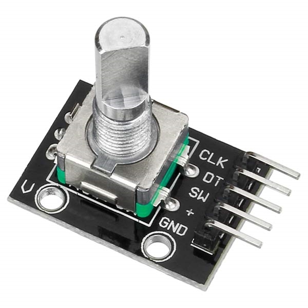
A rotary encoder is an electro-mechanical device which converts the angular position or rotation of its shaft or axle to an analog or digital signal. They are used in several systems where precision and feedback in terms of rotational motion or angular position are required. Another good feature of the rotary encoder which is handy for this tutorial is that they come with buttons attached, so it can be clicked by pressing the knob and this is recognized by the Arduino just as it will if it were any other button or switch.
A menu is one of the easiest ways through which users can interact with devices with diverse features. From Smartphones to PCs and even TVs, it is used in almost every electronic device with a screen and navigating through it is done usually by pressing certain buttons to move up/down, right/left and make selections. However, in some recent smart devices, either for aesthetics or for an improved form factor, a knob-like approach is employed for navigation. For today’s tutorial, we will explain how to create a menu with the same Knob style control, using a rotary encoder.
Arduino Menu Tutorial with a Rotary Encoder and a Nokia 5110 LCD display – [Link]
We have published quite a number of tutorials using different displays with the Arduino, with the most recent being the tutorial on displaying graphics on all kind of displays with Arduino. For today’s tutorial, we will look into achieving more with displays by implementing a menu based system with the Nokia 5110 LCD display and the Arduino. The menu is one of the easiest and most intuitive ways through which users interact with products that require navigation. From mobile phone to PCs, its applications are endless. Today we will explore how to add this cool feature to your Arduino project.
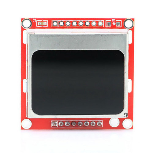
At the heart of today’s project is the Nokia 5110 LCD Display. The Nokia 5110 LCD is one of the most popular LCD display among makers. It was originally developed for use as a screen for cell phones and was used in lots of mobile phones during the 90’s. The display uses a low power CMOS LCD controller/driver, the PCD8544, which drives the 84×48px graphics display. In a normal state, the display consumes about 6 to 7mA which makes it quite ideal for low power devices. We have published quite a number of tutorials on this display that might help you understand how to drive such a display.
Menu on Nokia 5110 LCD display with Arduino – [Link]
In our last tutorial, we examined how to create a menu for your Arduino project on a Nokia 5110 LCD, with push buttons to navigate through it. In today’s tutorial, we will build a modified version of it which will make use a rotary encoder (in place of the push buttons) for menu navigation.
A Rotary Encoder
A menu is one of the easiest ways through which users can interact with devices with diverse features. From Smartphones to PCs and even TVs, it is used in almost every electronic device with a screen and navigating through it is done usually by pressing certain buttons to move up/down, right/left and make selections. However, in some recent smart devices, either for aesthetics or for an improved form factor, a knob-like approach is employed for navigation. For today’s tutorial, we will explain how to create a menu with the same Knob style control, using a rotary encoder.
Rotary Encoders are used in several systems where precision and feedback in terms of rotational motion or angular position are required. By turning the shaft to the right or left, we either get an increase or decrease in value (depending on the configuration). One of the major advantages of rotary encoders is the fact that their rotation is limitless. If the maximum position, (which is 20 for the particular rotary encoder used in this tutorial) is reached, the device starts the position counting all over again while the value attached to the position continues to increase/decrease with every turn of the knob in the same direction. Another good feature which will be handy for this tutorial is that they come with buttons attached, so it can be clicked by pressing the knob and is recognized by the Arduino just as any other button or switch.
Required Components
The following components are required to build this project;
As usual, the exact components used for this tutorial can be purchased via the links attached to each of them.
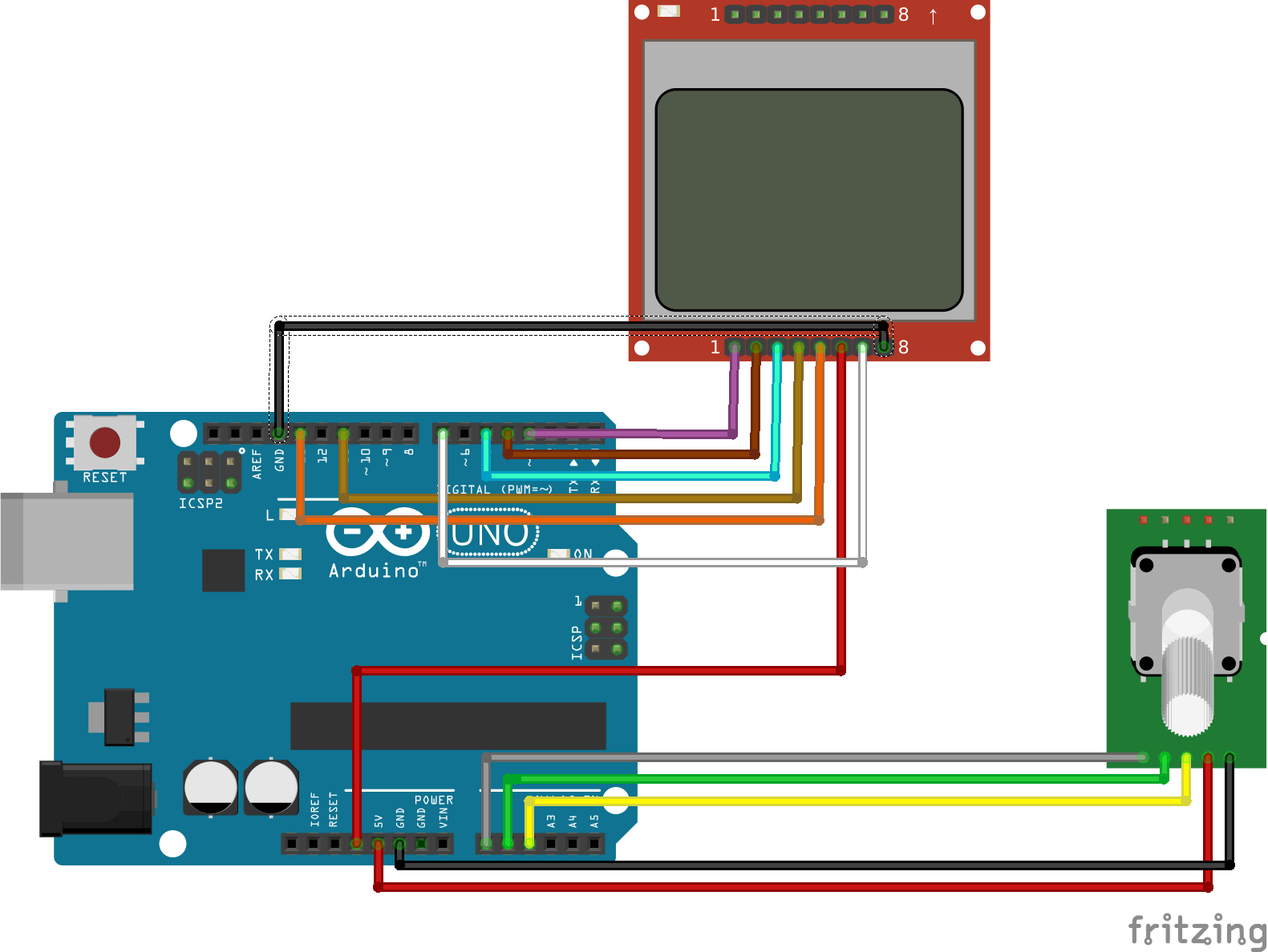
Schematics
The schematics for today’s project is almost similar to the one of the last tutorial. We will take out the three push-buttons and add a rotary encoder. Connect the components as shown in the schematics below.
Schematics
The rotary encoder used is an analog device, and for that reason all its three output pins are connected to analog pins on the Arduino.
To make the connections easier to follow, a pin map between the components is provided below.
Go over the schematics once again to ensure everything is as it should be then let’s proceed to write the code.
Code
The code for this version of the tutorial is a little bit more complex compared to that of the last tutorial and you may need to replicate it yourself before you really understand the full scope of it.
To simplify/reduce the amount of work we need to do, we will use four libraries. Two of the libraries; the Adafruit GFX library and the Nokia 5110 LCD library, will be used to interact with the display while the other two; the Encoder Library and the TimerOne library, will reduce the amount of code we write to interact with the rotary encoder. Each of the libraries can be downloaded via the links attached to them or installed via the Arduino Library Manager.
To briefly explain the code;
As usual, we start by including the libraries that will be used for the project.
Next, we create variables to hold the menus alongside an object of the click encoder and the LCD library.
int menuitem = 1;
int frame = 1;
int page = 1;
int lastMenuItem = 1;

String menuItem1 = "Contrast";
String menuItem2 = "Volume";
String menuItem3 = "Language";
String menuItem4 = "Difficulty";
String menuItem5 = "Light: ON";
String menuItem6 = "Reset";

boolean backlight = true;
int contrast=60;
int volume = 50;

String language[3] = { "EN", "ES", "EL" };
int selectedLanguage = 0;

String difficulty[2] = { "EASY", "HARD" };
int selectedDifficulty = 0;

boolean up = false;
boolean down = false;
boolean middle = false;
ClickEncoder *encoder;
int16_t last, value;

Adafruit_PCD8544 display = Adafruit_PCD8544( 5, 4, 3);//This only works with recent Adafruit Nokia 5110 library. Ensure yours is up to date
Next, we write the void setup() function. We start by declaring the pin to which the LCD’s backlight is connected (D7) as output and then proceed to create an encoder object before initializing the display and the rotary encoder, setting it to start at zero. We also create an interrupt routine which will be used to detect button press within any of the menu pages.
Up next is the void loop() function. This function is the most complex part of the whole code. The function basically creates the menu and uses the variables created initially to keep track of the previous, current and next state so when the rotary encoder is turned, it knows the right menu to display. The menu selection part of the code is also handled by a routine within the void loop() function.
We start by creating the menu using the drawMenu() function.
void loop() {

  drawMenu();
Next, we call the readRotaryEncoder function to obtain the control inputs from the rotary encoder.
readRotaryEncoder();

 ClickEncoder::Button b = encoder->getButton();
 if (b != ClickEncoder::Open) {
 switch (b) {
    case ClickEncoder::Clicked:
       middle=true;
      break;
  }
}
Next, Data from the encoder is fed into a series of if-else statements which checks if the encoder was clicked or turned in a particular direction and which of the screens is currently being displayed to determine what action is to be done next. For instance, the first if statement checks if the menu is currently on page 1 and if the encoder is turned to the right (indicates up). If this is the case, it then checks the position of the menu cursor and adjusts it accordingly.
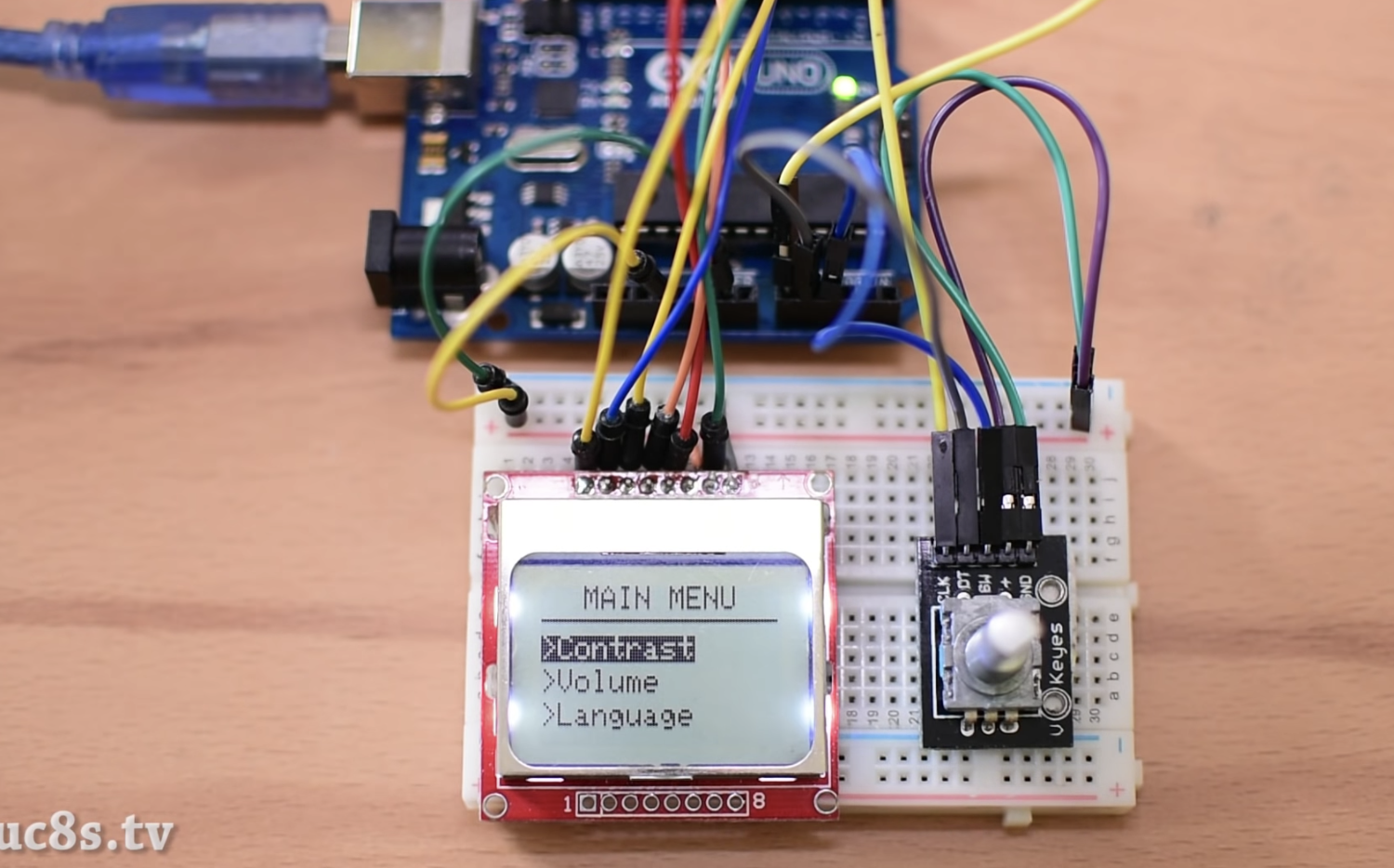
Verify your connections, by comparing with the schematics above, to ascertain that everything is as it should be. With that done, connect your board to the computer and upload the sketch to it. You should see the screen come on with the menu displayed. Try to turn the knob in different directions to navigate the menu and use the click feature of the knob to select an option.
Demo
That’s it for today’s tutorial, thanks for reading and building along. What project will you add this cool feature to? Share via the comment section below. Also, reach out via the comment section if you have any question.
Till next time!
The video version of this tutorial is available on Youtube.
RS-485 has been the industry’s most used wired communications interface for more than decades. Balanced differential signaling of RS-485 allows for rejection of common mode noise and facilitates communications over long distances in noisy industrial environments. RS-485 is a common communications port in most industrial applications such as factory automation, protection relay, energy meter, motor drives and building automation.
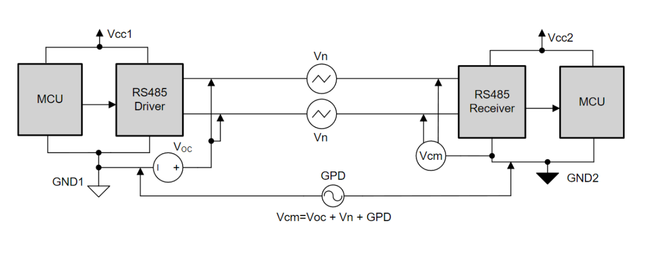
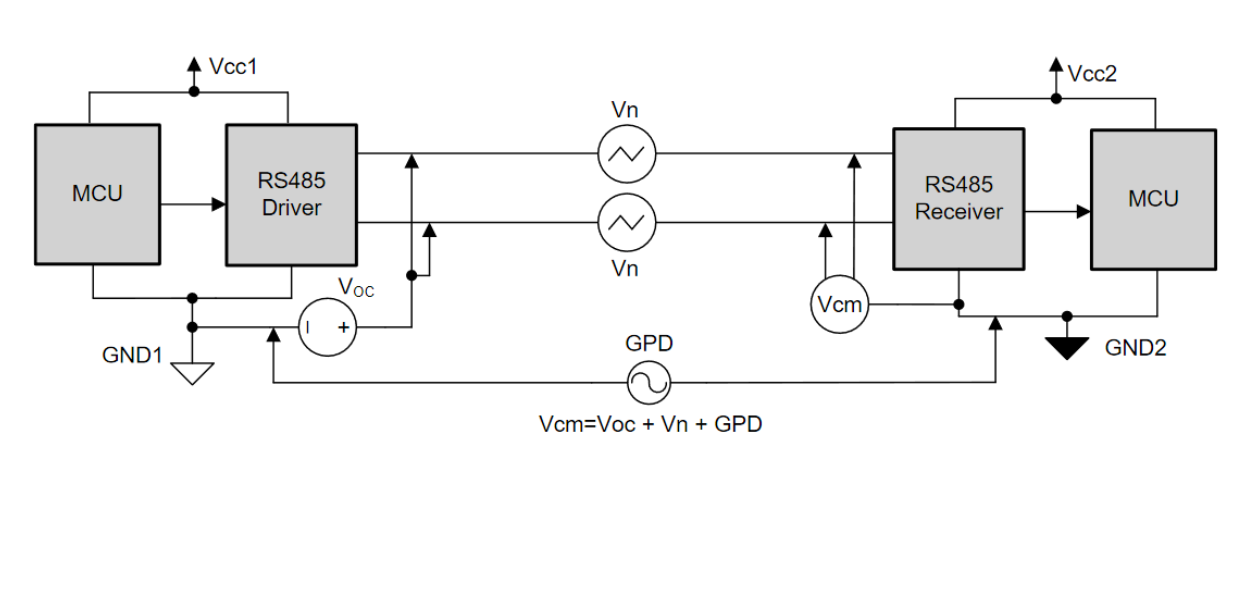
TIA/EIA-485-A standard defines that the compliant transceivers must work with ±7 V ground potential difference (GPD). As shown in Figure 1, common mode voltage on receiver bus pins (Vcm) is a sum of GPD, driver output common mode voltage (Voc) and any common mode coupled noise (Vn) to the bus pins. As the communication distance between the nodes increases leading to higher GPD or as the industrial environment becomes noisier thereby coupling more common mode noise on the bus, the common mode voltage on receiver bus pins moves out of its recommended operating condition. This can lead to data corruption or damage to the transceiver.
How to isolate RS-485 – smaller size and high reliability – [PDF]
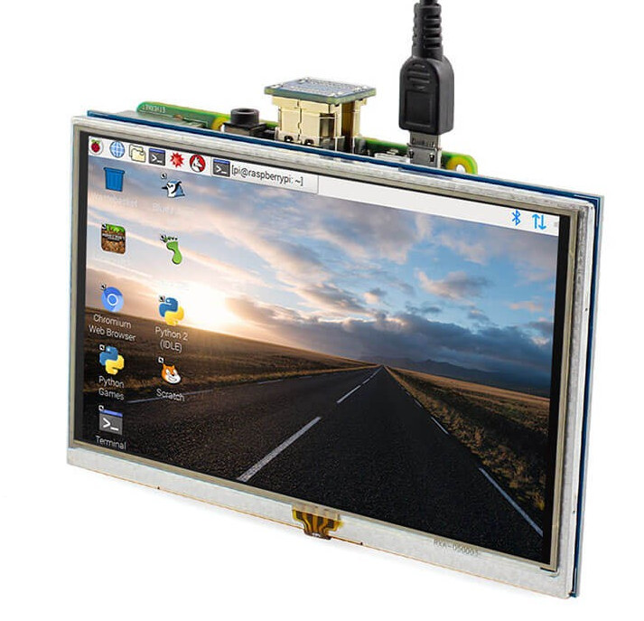
Elecrow has just launched a new 5″ HDMI display with resistive touch screen designed for the Raspberry Pi boards, and whose main feature is to support backlight control over GPIO 11 in order to lower power consumption.
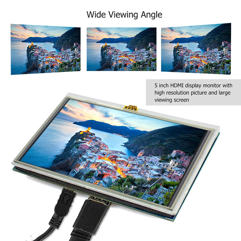
This is a 5 inch mini HDMI touch screen for Raspberry Pi, with high resolution that will provide a large viewing screen for Raspberry Pi. Compared with another type of 5-inch display sfor Raspberry Pi, the backlight of this 5-inch display can be controlled by Raspberry Pi GPIO pin 11. Generally, the backlight is on, then input a high level, it will turn off. The Pin 11 control a MOS tube switch on or off, the MOS tube switch will enable and disable the EN end of the backlight power IC. This design makes it convenient to control the backlight when we put the display into a product, and safe power at the same time.
Although this 800×480 HDMI display is designed for Raspberry Pi, you can also use it with any computer that has HDMI output.
Power Supply – 5V/1A via micro USB port or Raspberry Pi header
Dimensions – 121.11 x 77.93mm
Weight – 175g
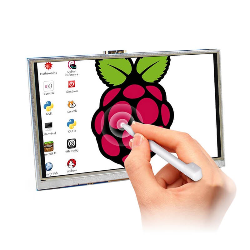
The resistive touch and backlight control functions will only work with a Raspberry Pi model B, 2B, 3B, or 3B+, and potentially Raspberry Pi compatible boards such as Tinker Board or Rock64, but you’d need to carefully check the pins used on the RPI header and potentially modify the software. This 5″ HDMI touch screen display can be purchased directly on Elecrow store for $39.90 plus shipping.
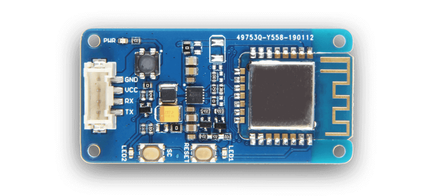
Seeed Studio launched its Air 602 module in October last year and it was the first ESP competitor that retailed cheaper than the Espressif ESP8266 and ESP32 modules. Due to the lack of FCC certification for the Air 602 modules, integrating the module into a product seemed problematic. However, Seeed Studio announced early this year a new module, and two new development boards, designed based on the same chip as the Air 602 modules. The new boards are modeled around the same WinnerMicro W600 which features an Arm Cortex-M3 with 1MB of Flash on-chip with 2.4GHz support.
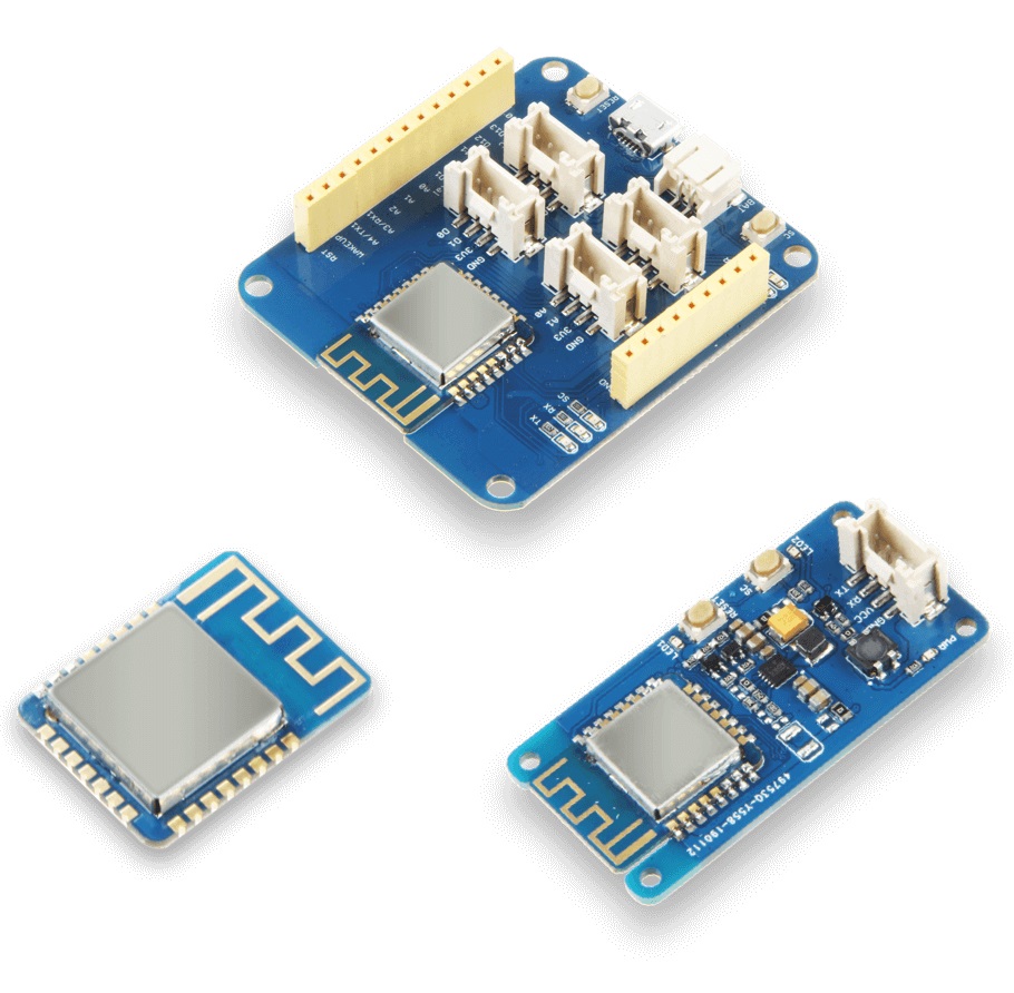
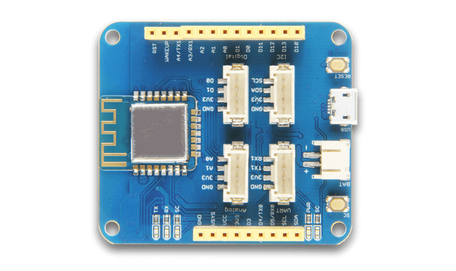
The new W600 wireless module is an FCC and CE pre-certified Wi-Fi module. The module has an on-module antenna and is mostly just an RF shield on a PCB. One of the two new boards is the Grove W600, which is powered by the W600 module, and it allows you to add Wi-Fi support to devices via serial UART using Seeed’s Grove System. It features a number of additional pins than those available in the Air 602 development board. The second board is a more conventional W600 Development Board, which breaks out all of the pins available by the W600.
Grove W600 Module
The board has four Grove System connectors, as well as a LiPo battery connector. It isn’t expected to ship until sometime during the second quarter of the year. Significantly, the board will ship with support for both the Arduino development environment and MicroPython. The documentation on the W600 is sparse, and the documentation that is available is mostly in Chinese. At the moment, the board functions as a serial to W-Fi bridge and its functionality doesn’t go beyond that, but the incorporation of Arduino and MicroPython support will address that.
W600 Development Board
The W600 chip at the center of these modules features an Arm processor. This makes it interesting for those experimenting with machine learning on the edge, and for those building the Internet of Things. The W600 wireless module and the W600 Grove Module are available from Seeed Studio. You can pre-order the castellated wireless module, priced at $3.79 per unit, including shipping, as well the W600 Grove Module for $7.49 per unit plus shipping. The estimated availability date of both modules is May 22nd-23rd.
There’s no information around price points, or the exact ship dates, for the W600 Development Board. However, Seeed Studio has provided a Wiki and opened a forum section, to get updates. You can sign up for email updates on the W600-based boards on the Seeed Studio site.
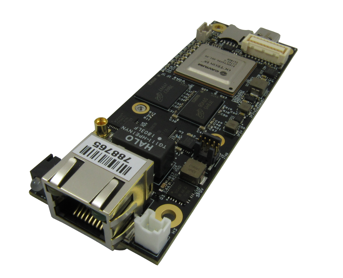
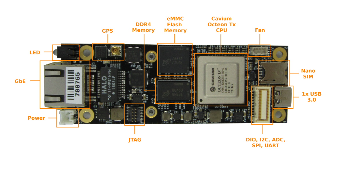
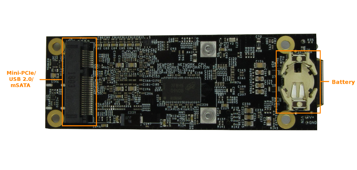
A Miniature 35x100mm Single Board Computer for Networking with Mini-PCIe Socket, Gigabit Ethernet Port, and USB Type-C TM 2.0 Port.
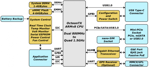
The GW6100is the smallest member of the Gateworks 6th generation Newport family of single board computers targeted for a wide range of indoor and outdoor networking applications. The GW6100 features the Cavium OcetonTX™ Dual Core ARMv8 SoC processor operating at 800MHz, 1GByte of DDR4 DRAM, and 8GBytes of eMMC System Flash. A Mini-PCIe expansion socket supports 802.11abgn/ac wireless radios, LTE/4G/3G CDMA/GSM cellular modems, mSATA drives and other PCI Express peripherals. Additional peripherals include a Gigabit Ethernet port and a USB Type-C™ port. The Gateworks System Controller provides embedded features such as real time clock, voltage and temperature monitor, fan control and monitor, serial EEPROM, and advanced power management with programmable board shut-down and wake-up for remote sensor applications. A wide-range DC input power supply provides up to 8W to the Mini-PCIe socket for supporting the latest high-power radios and up to 7.5W to the USB Type-C™ port for powering external devices. Input Power is applied through dedicated connector or the Ethernet port in a Passive Power over Ethernet configuration. Both OpenWrt and Ubuntu Linux Board Support Packages are supported.
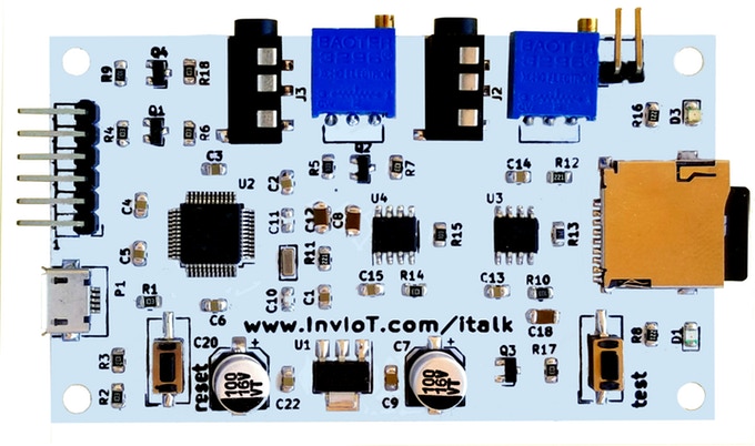
Add speech to your projects. Raspberry & Arduino compatible. Use ‘serial port’ to send speech text in any language. .WAV Player.
Make it simple to add speech to any of your projects. It only takes 3 wires to connect it with an Arduino or a Raspberry. By coping a .WAV file on the SD, you can play music, a prerecorded sentence or combine it with word synthesis.
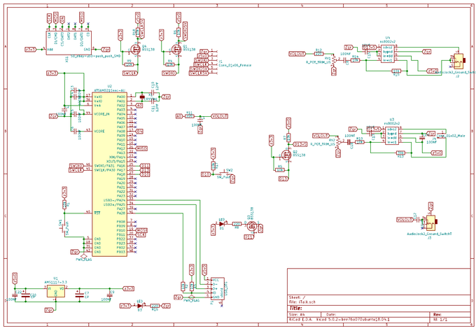
The TextToSpeech board synthesizes audio output from text via a Microchip SAMD21G18 MCU paired with an Arduino Zero bootloader. You can also play back .WAV files with music and pre-recorded speech and output them via the board’s 3W speaker amp.
Hardware
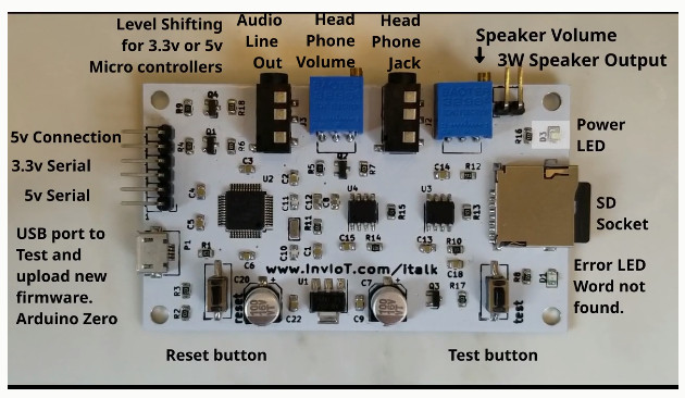
Build in 3W speaker amplifier with a trimmer for the speaker volume, an audio line output jack and headphone amplifier. lt also includes a separate trimmer for the headphone volume.
A low-pass RC filter is used to cut any high frequency noise.
The word synthesis is done with an SAMD21G18 micro controller, running with an Arduino Zero bootloader.
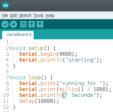
You must always power the board with 5v. Text is sent to the board thru USB Serial communication or by UART connection. There is a level shifter so a 5v (Arduino UNO, etc) or a 3.3v (Arduino Zero, Raspberry Pi, etc.) micro controller can be used. Both can work simultaneously.
The default serial speed is 9600, but the speed can be changed by editing the file ‘setup.txt’ found in the SD card. In this file you can also change the bit rate (default 22050), the bit resolution (default 8 bits), and the speed of the text (default 100).
An error LED is turned on when a word is not found in the SD card. Also there is a test button, so you can hear that the board is working
Software
The Text-To-Speech board has an SD card where all the words pronunciation are stored.
When a text is sent to the Text-To-Speech board, the word synthesis begins, it quickly finds the words pronunciation in the SD card from your picked language/voice folder and word synthesis for the sentence begins.
No need to install any library. Power it up with 5v, connect it by using only one pin (Tx pin) to an Arduino compatible (3.3v or 5v) or a Raspberry Pi and just send your text thru your serial port.
So far they created 4 packages:
7,000 English words package language using a real human voice from Wikipedia project
20,000 English words by using the software from http://espeak.sourceforge.net
10,000German words by using the software from http://espeak.sourceforge.net
10,000 French words by using the software from http://espeak.sourceforge.net.
The TextToSpeech board is available on Kickstarter through June 27 starting at $24 or $36 (with SD card), with shipments due in September. More information may be found on InvIoT’s TextToSpeech Kickstarter page.