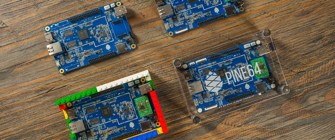
The FOSDOM, is a free event for software & hardware developers to meet, share ideas and collaborate with each other that has also turned to an avenue where organizations, startups, and even lone wolfs use to launch or announce their latest line of technological solutions. The FOSDOM 2019 also continues the same trend with Pine64 launching a new series of hardware-based products, a pattern they continue after doing so before.
PINE A64
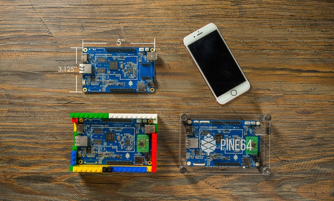
Pine64 came to limelight with the launch of their supposed Raspberry Pi killer called the Pine A64 in 2015, that was launched on Kickstarter and even grossed over $1 million but never live up to its mission of killing off the Raspberry Pi despite its mouthwatering $15 unit cost. The same fate that came upon the Pine A64 has fallen on tens of other similar boards, and the Raspberry Pi is still standing strong and not going down anything soon.
Some of the exciting products debuted by Pine64 during the event are shown below:
The Pine H64 Model B
The Rock64 Revision 3
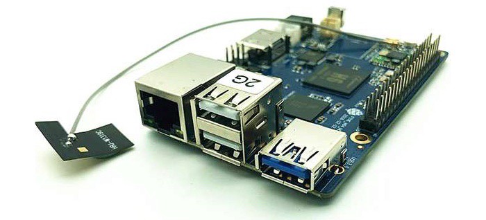
The Pine H64 Model B
The Pine H64 Model B
The Pine H64 Model B is a replacement of its predecessor the Pine64 H64 which was also announced at last year’s FOSDEM event. The Pine H64 shares similar attributes with the older H64, but a significant change is the board footprint which replicates the smaller Rock64 footprint as compared to the bigger H64 size. The board is built around the Allwinner H6, a quad-core Arm Cortex-A53 SoC with a Mali-T720 MP2 dual-core GPU capable of 4K60 playback and HDR
Like its predecessor, the board comes in three variants and costs $25 for the 1GB version, $35 for the 2GB version, and $45 for the 3GB version.
The device specification
SoC: Allwinner H6 (Quad-core, Arm Cortex A53-based processor)
GPU: Dual-core Mali-T720 MP2
Storage:
eMMC flash module
Micro SD card
Video: HDMI 2.0a output
Audio: 3.5mm stereo earphone
Connectivity:
Gigabit Ethernet
Wi-Fi
Bluetooth
USB:
2 x USB 2.0 host & 1 x USB 3.0 host
Expansion:
2 x 20 Raspberry Pi 2-compatible GPIO header
Mini-PCIe connector
Wi-Fi/Bluetooth module header
SDIO 3.0
UART
IR receiver
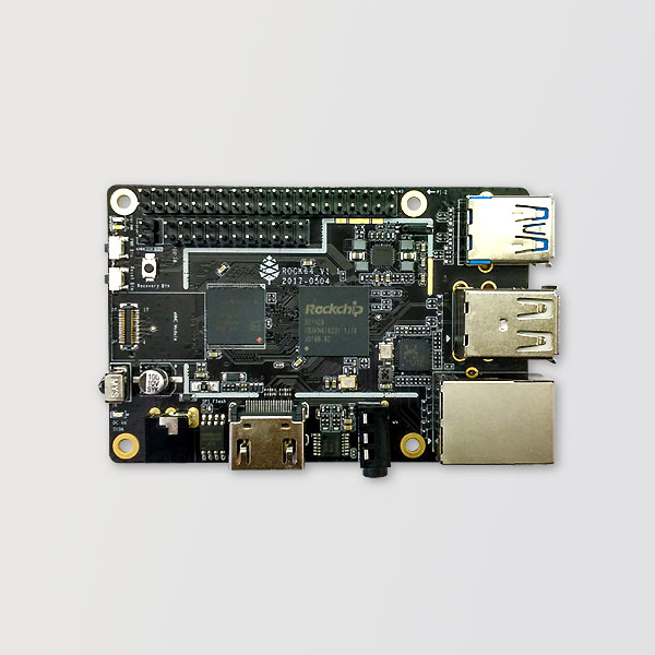
The Rock64 Revision 3
The Rock64 Revision 3
Pine64 has launched a new revision for their well know Rock64 board. The Rock64 is the most popular and successful board ever created by the Pine64 team, and the board is one of those developers somehow found peace with. The ROCK64 is a credit card size 4K60P HDR10 Single Board Computer powered by Rockchip RK3328 Quad-Core ARM Cortex A53 64-Bit Processor and supports up to 4GB 1600MHz LPDDR3 memory. It provides eMMC module socket, MicroSD Card slot, Pi-2 Bus, Pi-P5+ Bus, USB 3.0 and many other peripheral devices interface for makers to integrate with sensors and devices.
The new version 3 of the board adds the below:
Power-over-Ethernet (PoE) support
A Real Time Clock (RTC)
Improved Raspberry Pi I/O compatibility
Minor improvements
support for high-speed micro SD Cards.
Just like the older models, the pricing will remain the same with the 1GB model priced at $24.95, the 2GB model at $34.95, and the 4GB model at $44.95.
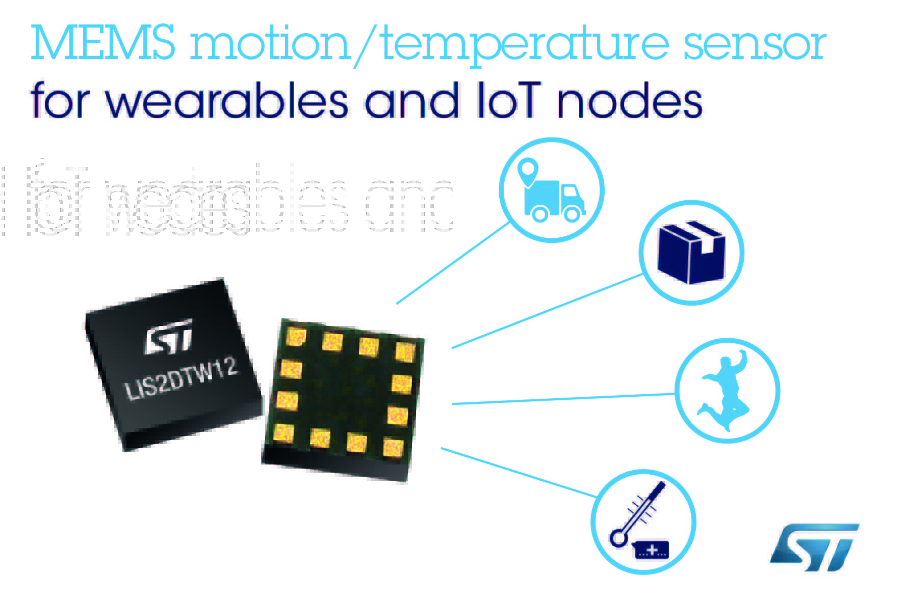
The LIS2DTW12 is an ultra-low-power high-performance three-axis linear accelerometer and temperature sensor belonging to the “femto” family which leverages on the robust and mature manufacturing processes already used for the production of micromachined accelerometers.
The device has user-selectable full scales of ±2g/±4g/±8g/±16g and is capable of measuring accelerations with output data rates from 1.6 Hz to 1600 Hz.
The LIS2DTW12 has an embedded 0.8 °C (typ. accuracy) temperature sensor with ODRs ranging from 50 to 1.6 Hz and resolution from 8 to 12 bits.
The LIS2DTW12 has an integrated 32-level first-in, first-out (FIFO) buffer allowing the user to store data in order to limit intervention by the host processor.
The embedded self-test capability allows the user to check the functioning of the sensor in the final application.
The device has a dedicated internal engine to process motion and acceleration detection including free-fall, wakeup, highly configurable single/double-tap recognition, activity/inactivity, stationary/motion detection, portrait/landscape detection and 6D/4D orientation.
The LIS2DTW12 is available in a small thin plastic land grid array package (LGA) and it is guaranteed to operate over an extended temperature range from -40 °C to +85 °C.
Key Features
Ultra-low power consumption: 50 nA in power-down mode, below 1 µA in active low-power mode
Very low noise: down to 1.3 mg RMS in low-power mode
0.8 °C (typ. accuracy) embedded temperature sensor
Multiple operating modes with multiple bandwidths
Android stationary detection, motion detection
Supply voltage, 1.62 V to 3.6 V
Independent IO supply
±2g/±4g/±8g/±16g full scale
High-speed I²C/SPI digital output interface
Single data conversion on demand
16-bit accelerometer data output
12-bit temperature data output
Self-test
32-level FIFO
10000 g high shock survivability
ECOPACK, RoHS and “Green” compliant
more information and samples ordering on www.st.com
Powerful new tool facilitates first-time-right analog & high voltage design implementation in even the most challenging of scenarios.
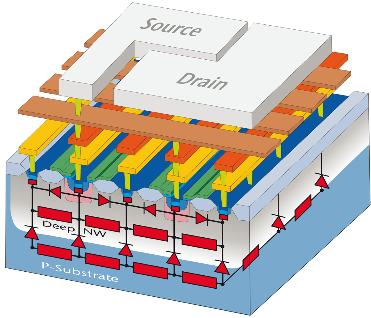
Continuing to drive innovation in analog/mixed-signal IC fabrication, X-FAB Silicon Foundries SE (http://www.xfab.com/) has announced the introduction of SubstrateXtractor.
Unwanted substrate couplings can impact modern IC developments, causing parasitic effects that are damaging to overall performance. Engineers have to deal with this by taking a slow and laborious ‘trial and error’ approach, which calls for the allocation of many hours of experienced engineers’ time while numerous different design iterations are made and then experimented with.
The objective of SubstrateXtractor is to change all that. Created in partnership with Swiss EDA software vendor PN Solutions, and based on its innovative PNAware product, this is the semiconductor industry’s first commercially available tool dedicated to addressing the simulation of large signal substrate parasitic effects. Working in conjunction with X-FAB’s established simulation libraries, it allows engineers to investigate where potential substrate coupling issues could occur and make the changes necessary to eliminate them (via better floorplanning, guard rings, etc.) before the initial tape-out has even begun.
Through it, engineers will gain full visibility of all the active and passive elements within the substrate and be able to experiment with different simulations in order to find a design concept that delivers maximum substrate coupling immunity within the project’s particular parametric constraints. Furthermore, they are able to determine the minimum number of substrate contacts and guard rings needed for a project, no matter how complex and sophisticated it is – thereby resulting in more effective utilization of the available area.
“By employing the SubstrateXtractor tool, layout engineers will be able to uncover any adverse substrate effects early on in the development cycle and subsequently mitigate them,” explains Joerg Doblaski, Director of Design Support at X-FAB. “This will make IC implementation procedures far more streamlined and quicker to complete, avoiding the need to rework designs to increase levels of optimization, and resulting in significant cost savings.”
SubstrateXtractor is set to dramatically reduce the number of design iterations required – leading to much lower engineering overheads. This results in a faster time to market making a first-time-right analog design possible. From now onwards this functionality will be integrated into X-FAB’s process design kit (PDK) and available for use with the company’s popular XH018 (https://www.xfab.com/technology/cmos/018-um-xh018/) high voltage 0.18µm mixed-signal CMOS offering. A version for the power management process XP018 will soon follow. A detailed webinar on this valuable new tool will be hosted on May 22nd and 23rd. For details and to register, click here (https://register.gotowebinar.com/rt/7742535881476974860).
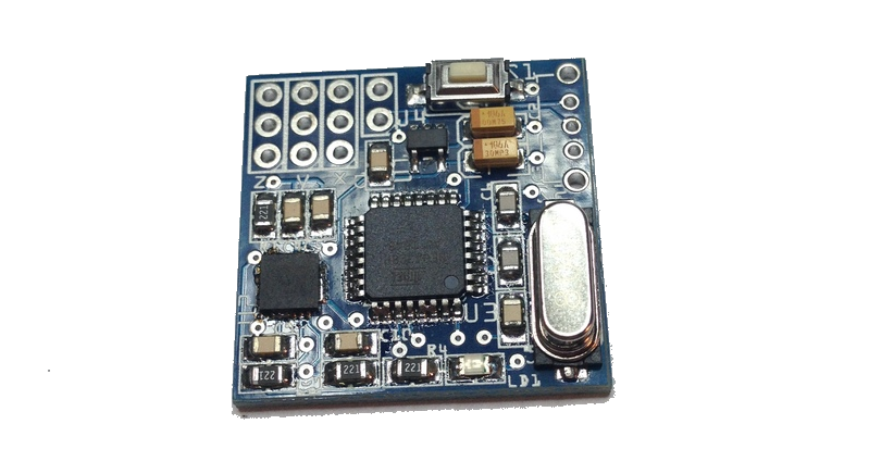
Zita V2 is a tiny and lightweight 3 axis wireless gyroscope with PPM output option. The project is live on kickstarter and has 10 days to go.
Perfect for FPV head tracking, robotics, movement control and why not video games. The 3 axis motion sensor gyroscope allows you to track the movement of the head or arm and replicate it to servos. Like the wired version Iota V2, the Zita V2 can be configured as normal or reverse action mode but wirelessly! It can also outputs signals in PPM. For Do It Yourself (DIY) home project lover who dreams of doing a head tracking system FPV themselves. This system has been specially designed for DIY in electronics or robotics for all ages people who wants to explore electronics and want their own system, but are less comfortable with advanced programming of accelerometers. You can use one or more axes (X, Y, Z) independently. According to your needs.
New modulation method increases operational lifetime of switching power units through digital, highly dynamic control and the use of film capacitors.
Switching power units are used for the power supply of many electrical devices, e.g. computers, LED lights or laser welding equipment. They convert alternating current from the mains into the direct current required by the device. A frequent cause of failure of technical devices is the failure of the integrated power supply units. These thus limit the service live of the devices or require more frequent service intervals.
The electrolytic capacitors used in the power unit are particularly susceptible to faults. They buffer electrical energy and smooth voltage fluctuations over a mains period. Electrolytic capacitors offer a high energy density and are mostly regulated analogously. Film capacitors, on the other hand, would be much more durable. However, due to their lower energy density, these require ten times the installation space for the same capacity.
Scientists at the Light Technology Institute (LTI) at KIT have developed a new modulation process for the digital and highly dynamic control of power supply units that enables the use of film capacitors with only little increased installation space. For the first time, the method allows the output current to be controlled taking into account the DC link voltage and output voltage, whereby frequency and duty factor are possible control variables. The inclusion of these variables makes the control more robust, safer and faster. Input and output voltages are also considered, which improves control inaccuracies.
As a result of the longer operational lifetime of the film capacitors used, the failure rate of the switching power units can be reduced and thus the durability of the terminal devices can be increased many times over. Reduced maintenance effort is particularly useful in places that are difficult to access or with high-quality devices, e.g. electric cars. Due to the accuracy and flexibility of the highly dynamic control, power supply units of this type are particularly advantageous for industrial applications with high dynamic requirements. In addition, Internet of Things integration for remote diagnosis or remote maintenance is also possible without any problems.
A functional prototype was set up at the institute and measurement results, including lifetime measurements, are available. KIT is looking for industrial partners to develop application-specific, high-quality power supplies in the premium segment.
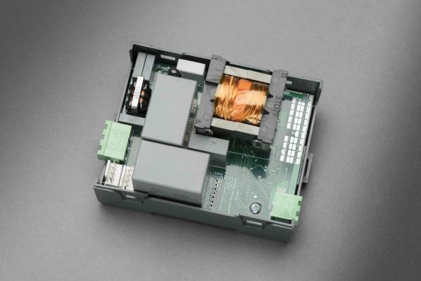
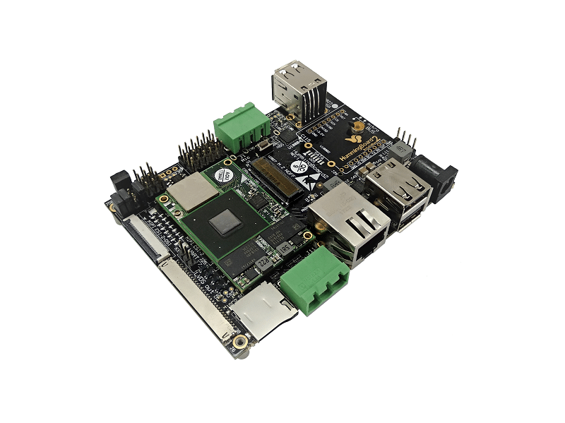
SolidRun has launched a new single board computer named as HummingBoardCBi. HummingBoard CBi merges the powerful HummingBoard platform with the CAN bus and RS-485 connectors – tailor-made for industrial and production floor applications. They actually swapped the HDMI of theirHummingboardEdge SBC with CAN and serial port to design this new industrial variation. This board runs Linux on an i.MX6 MicroSOM just like the Hummingboard Edge.
HummingBoard CBi by SolidRun
The sandwich-style board, which ships with a regular enclosure, has the same 102 x 69mm footprint of the Edge and the HummingBoard-Gate and ships with open schematics. In their website, they represented this industrial SBC as a powerful carrier board for a range of interchangeable i.MX6 based SOMs, developed for the demanding industrial automation market to offer robust features for the smart production floor of tomorrow. CANbus (Controller Area Network) is a standard connector originally developed for the automotive industry. It offers a rugged connectivity option for designing a physical network in a harsh environment and has been used in a variety of sectors for a range of applications from vehicle engines to aviation, medical, smart building, or even robotics.
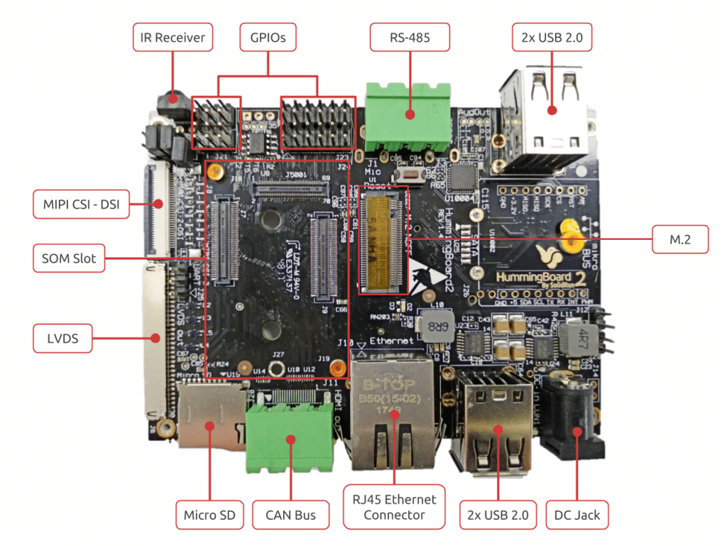
The HummingBoard CBi SBC/mini-PC runs Linux on the same NXP i.MX6 equipped MicroSOM modules with dual-or quad-core 1.2GHz Cortex-A9 cores. (A single-core Solo model is listed in the specs, but not yet available.) Debian, Yocto Project, BuildRoot, and OpenWrt stacks are available with a Linux 4.4x kernel, and Android support is in the works. It offers up to 2GB memory, USB 2.0 ports, Mini PCIe, M.2 and even a SIM card slot, all on a compact (102mm X 69mm) ARM-based and energy efficient industrial single board computer. Other features include the usual bandwidth-limited GbE port, 4x USB 2.0 ports, 8GB eMMC, and a microSD slot. Although it’s not listed on the product page, the shopping page says the board provides a WiFi/Bluetooth module.
The key specifications are:
Processor (via MicroSOM i.MX6): NXP i.MX6 (2x or 4x Cortex-A9 cores @ up to 1.2GHz)
Memory/Storage:
1GB (Dual) or 2GB (Quad) DDR3 RAM (via MicroSOM i.MX6)
8GB eMMC (via MicroSOM i.MX6)
MicroSD slot
M.2 2242 slot with storage support
Wireless: WiFi/Bluetooth module
Networking: Gigabit Ethernet port (limited to 470Mbps bandwidth)
The HummingBoard CBi is available with 8-week shipping time for $189 (dual-core with 1GB RAM) or $255 (quad-core with 2GB). More information may be found on the HummingBoard CBiproduct, developer, and shopping pages.
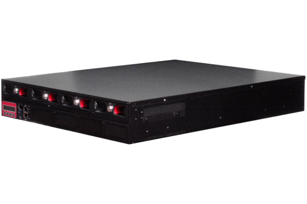
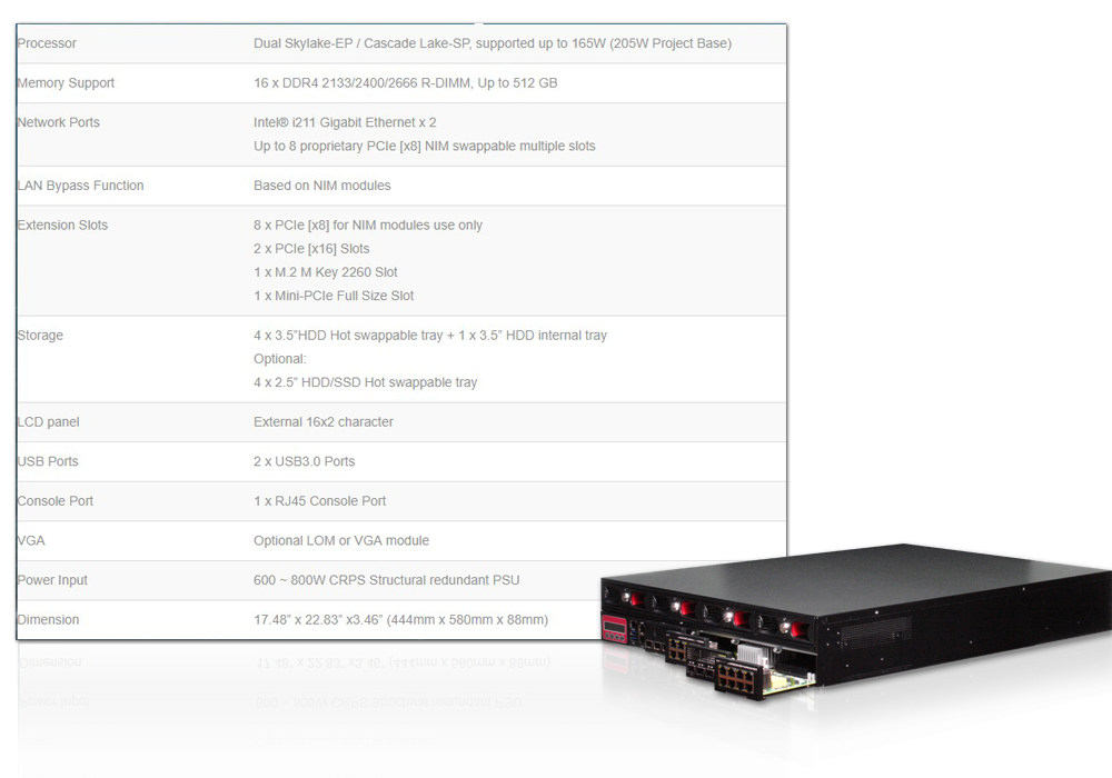
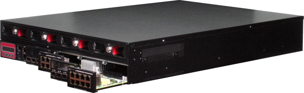
AAEON, an industry leader in network security solutions, has collaborated with Intel to deliver a powerful network platform utilizing the latest 2nd Generation Intel® Xeon® Scalable processors. The result of this effort is the FWS-8600 2U rackmount network appliance, the most powerful network appliance from AAEON yet.
The FWS-8600 network appliance is built to handle powerful network applications, from Unified Threat Management (UTM) to Software Defined Networks (SDN) and Network Function Virtualization (NFV). These features come from the appliance’s 2nd Generation Intel Xeon Scalable processors, offered with up to 20 cores per processor. The FWS-8600 uses a dual processor configuration, meaning users can have up to 40 processor cores powering their networks. The FWS-8600 also features four lockable hard drive bays, and 16 DDR4 memory slots, with support for up to 512GB of RDIMM ECC RAM.
Thanks to the speed and power of 2nd Generation Intel Xeon Scalable processors, the FWS-8600 can support LAN throughput up to 300~400 Gbs, ten times more than typical machines currently available, according to AAEON testing. This means the FWS-8600 can take the place of multiple network devices, simplifying network infrastructure. With support for network virtualization and software defined networking, the FWS-8600 can ensure high bandwidth and high data flow for your networks.
“With the power of 2nd Generation Intel Xeon Scalable processors, we can offer our customers a powerful, robust network platform that’s ready to handle the needs of the high data, high speed environment of IoT networks,” said Ulysses Yu, Product Manager of AAEON Network Security Division. “From a dedicated SDN controller, to a hybrid switch system, the FWS-8600 with the 2nd Generation Intel Xeon Scalable processor can power industrial network and IoT solutions,” added Ulysses.
The 2nd Generation Intel Xeon Scalable processor is the latest line of processors built for industrial and enterprise applications. AAEON looks forward to expanding our offerings of products featuring the 2nd Generation Intel Xeon Scalable processors.
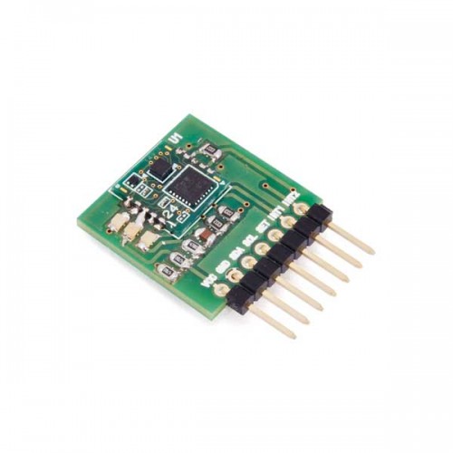
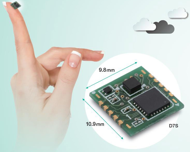
Fishmograph allows to precisely monitor earthquakes involving our house using the D7S sensor, sending us an email notification for every event detected, allowing us to take people and things to safety. Fishmograph is based on Fishino 32 and the excellent low-cost D7S sensor developed by Omron.
Italy is one of the Mediterranean countries with the highest seismic risk and this very unfavourable record is due to its geographic location, riding across the African plaque and the Euroasian plaque (we are talking about tectonic plaques); this “unfavourable” position causes the very high number of earthquakes taking place every day in our country, which, however, fortunately, are so weak that can be detected only by instruments, whilst a very small percentage has enough intensity to cause damages to people or things.
This sensor, which we have previously introduced and analyzed in this magazine in issue 222, guarantees a high degree of precision when detecting earthquakes and has the very useful automatic danger level evaluation feature for electronic devices, emitting a shutoff signal when intensity is 5 or higher on the JMA (Japan Meteorological Agency) intensity scale, or it can emit a collapse signal when a variation in its physical position is detected (possibly due to the floor collapsing).
Fishmograph – Omron’s D7S sensor based seismograph – [Link]
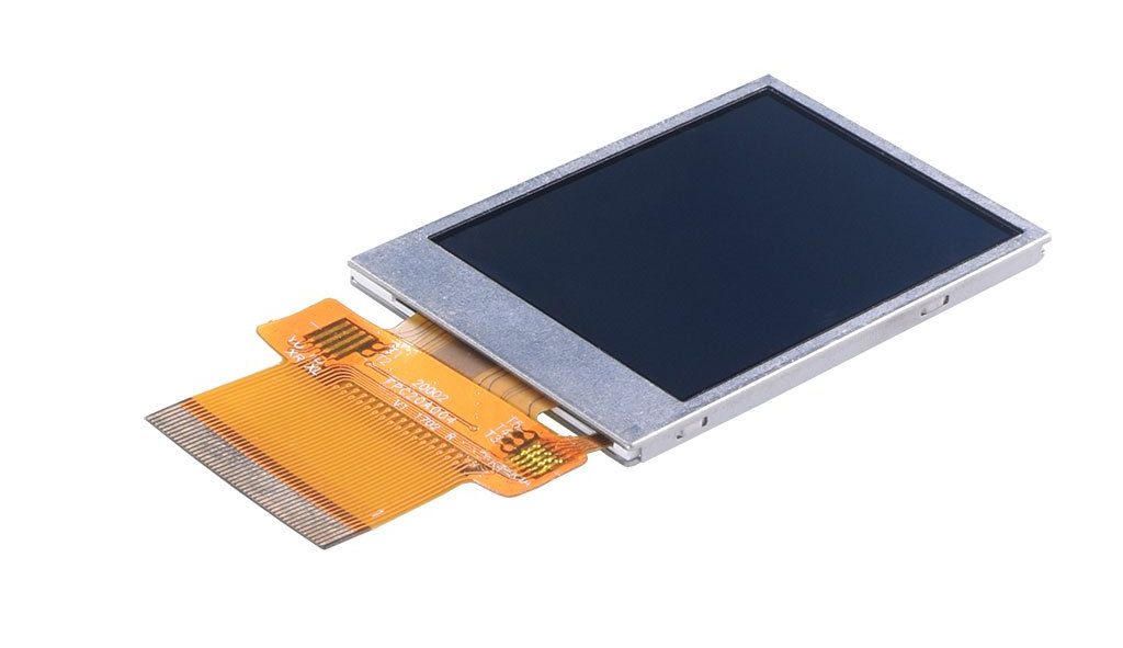
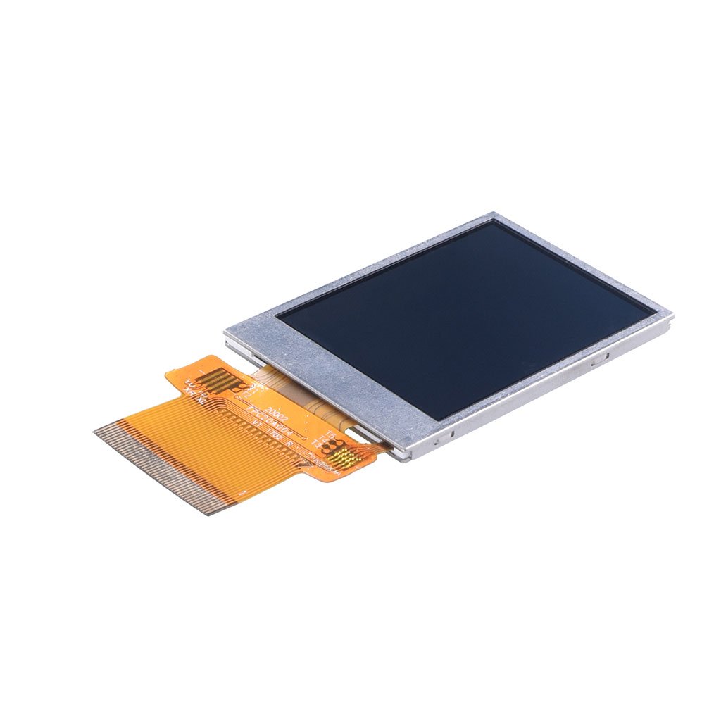
This is a new 2″ Transflective Display Panel with part number DM-TFT20-386 available from www.displaymodule.com for $15.99 . It can be interfaced to any microcontroller through SPI.
We can say that an Interrupt is an automatic transfer of software execution in response to a hardware event that is asynchronous with the current software execution. As it’s name says, interrupts, “interrupt” the normal program flow to perform an action (run another code block, function, etc.) and return back to the normal program flow when the action is completed. Interrupts can be established for events such as a counter’s number change, a pin changing state (from low to high or high to low), serial communication receiving information, or the Analog to Digital having established a conversion, etc., depending on what is supported by the microcontroller you are working with. For today’s tutorial, we will focus on interrupts as a result of pins changing state and how these can be used on the Arduino.
To monitor their digital pins for changes, microcontrollers by default use a technique generally referred to as “polling“, which means they constantly check the digital pins to know if any change has occurred. This usually takes a lot of the microcontroller’s resources and reduces its response time which may not be a problem in most applications but could be important in time-critical ones. One of the solutions usually adopted in scenarios where all the negatives of polling need to be eradicated is the use of external Interrupts. Interrupts provide the microcontrollers with a way of multitasking such that a particular digital pin does not need to be continually polled, as the pin would by itself signal the microcontroller and immediately pause the operations when a change occurs. Asides in time-critical applications, where the microcontroller needs increased response rate, Interrupts are widely used in power saving applications for all kind of device, from smartphones and their power button to your PC and the spacebar and the application goes on.
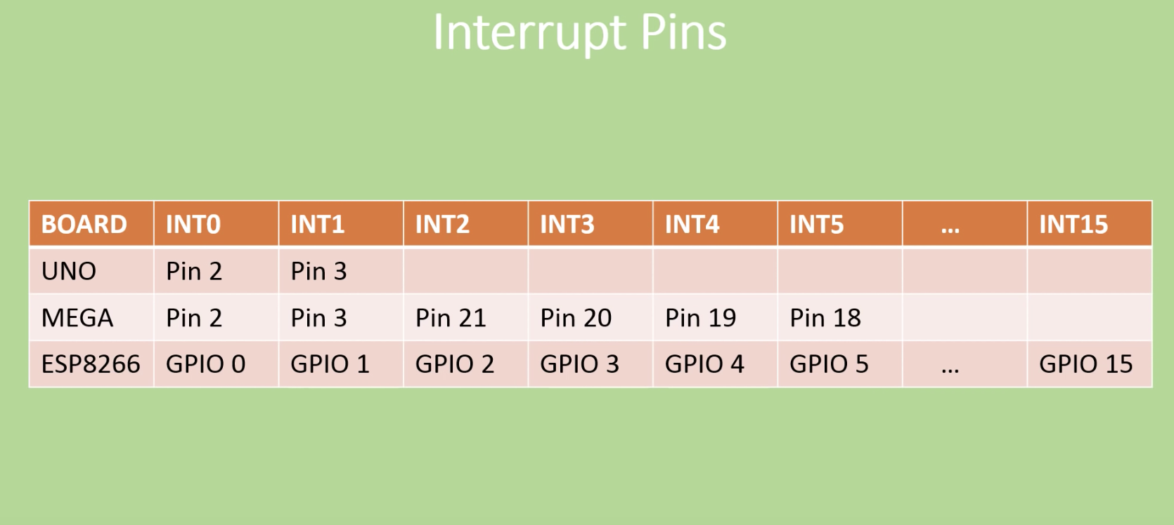
Interrupt Pins of different Arduino Boards
The number of external interrupts possessed by microcontrollers differs from one microcontroller to the other. For example, the Arduino boards, from UNO to Duemilanove, have only two interrupts which are located on digital pins 2 and 3. Other boards like the Arduino Mega has 6 while the esp8266 (ESP 12e) has about 16 interrupt pins.
For today’s tutorial, We will look at how the interrupt can be used in an Arduino project and as an example, we will connect a switch to one of the interrupt pins on the Arduino and use it to control a LED which is turned on/off when the interrupt is triggered.
Required Components
The following components are required to build today’s tutorial;
As usual, the exact components used for this tutorial can be bought via the link attached to them.
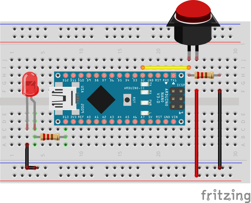
Schematics
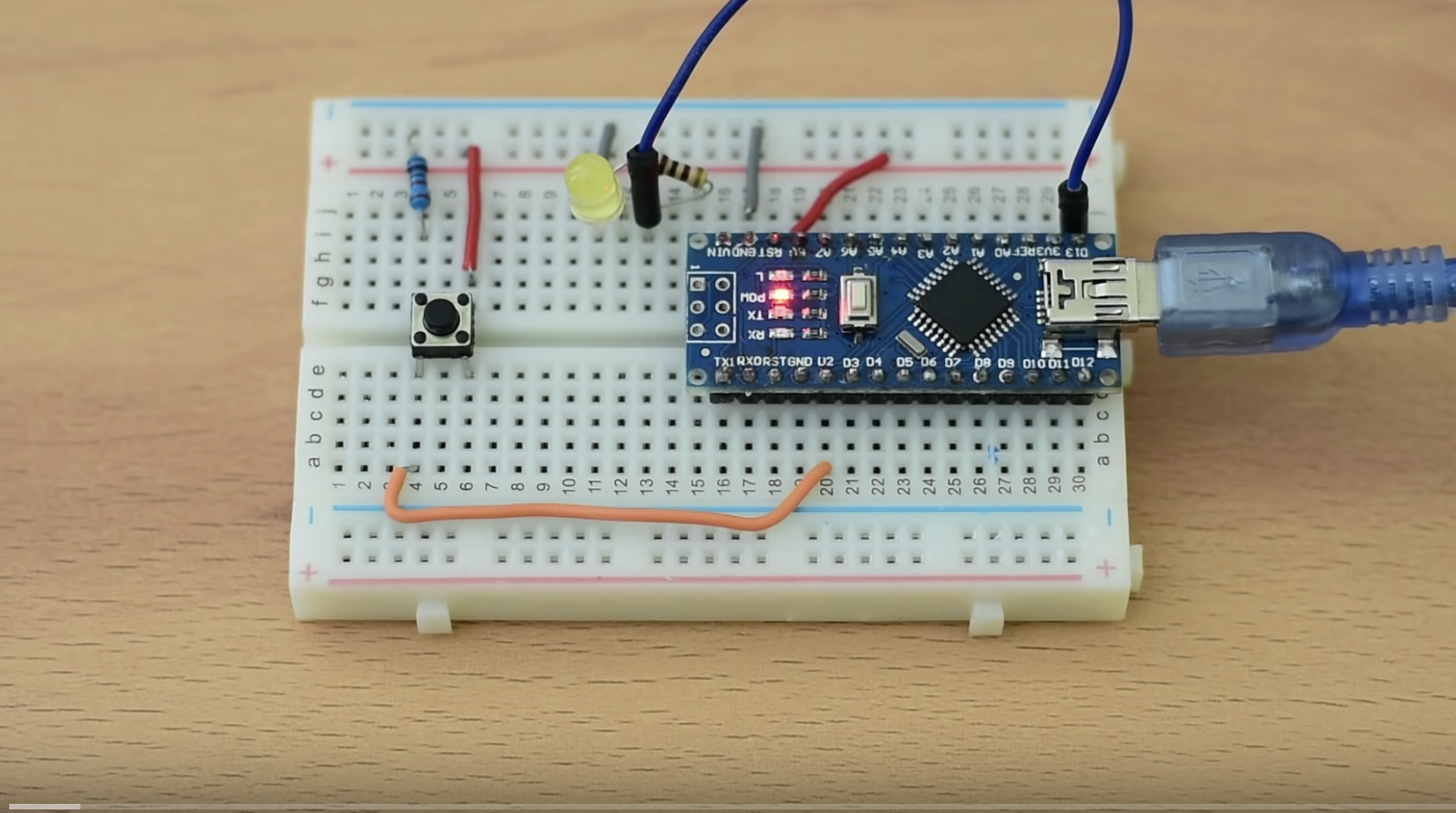
The schematics for this project is quite simple. We need to connect an LED and a pushbutton to the Arduino, in that way than when the pushButton is pressed, an interrupt is triggered on the Arduino to control the on/off state of the LED.
Connect the components as shown in the schematics below.
Schematics
As mentioned initially, either of the Arduino Uno and the Nano can be used for this project as they all have the same pin configuration, the same number of interrupt pins and the interrupt is located on the same pin across the two boards.
Asides using the switch as the trigger, a PIR Motion sensor can also be used to trigger the interrupt when motion is detected. To use the PIR sensor, connect it to the Arduino as shown in the schematics below.
Motion Interrupt Schematics
Since motion sensors behave like a switch, the same code can be used with the same schematics.
Code
The code for this project is quite easy. As mentioned at the beginning, our goal for today’s project is to learn how to perform an action (turn on/off and LED in this case) when an interrupt is triggered. Thus we will program the Arduino to watch out for a “rising edge” interrupt on the pin to which the button is connected and respond by turning the LED on.
To do a quick explanation of the code; We start by creating a boolean variable “ledon” to store the state of the LED. This helps the sketch remember the last state of the LED.
//Written by Nick Koumaris
//info@educ8s.tv

volatile boolean ledOn = false;
Next, we write the void setup() function. We start by declaring the pinMode of the pins to which the LED and the PushButtons are connected. With that done, we then call the attachinterrupt() function to provide the microcontroller with details of the interrupt operation. The attachinterrupt() function takes 3 arguments; The interrupt pin, the function to run when triggered, the type of trigger to look out for. The trigger could be either of “rising” (pin goes from low to high), “falling” (pin goes from high to low) or “either” (either of the two).
Since we won’t be repeating any action, we will leave the void loop() section blank. Thus, up next is the buttonpressed() function. This function is called when a rising edge signal triggers the interrupt. The function simply changes the state of the LED, turning it OFF if it was ON and turning it ON if it was OFF.
Go over the schematics once again to ensure everything is connected as it should then connect your Arduino to the computer and upload the code to it. You can now press the push button to see the LED respond.
Final thoughts
Interrupts are used for a plethora of applications including; implementing low power algorithms, eradicating polling to preserve system resources, and to ensure quick response in time-critical applications like alarm systems.
That’s it for today’s project. Thank you for reading. Do reach out via the comment section if you have any question or comments.
The video version of this tutorial is available on Youtube.