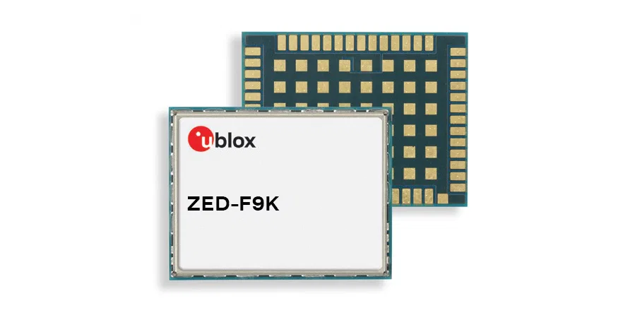
u-blox (SIX:UBXN), a global provider of leading positioning and wireless communication technologies, has announced the u‑blox ZED-F9K high precision multi-band GNSS (Global Navigation Satellite System) module with built-in inertial sensors. The module combines the latest generation of GNSS receiver technology, signal processing algorithms, and correction services to deliver down to decimeter-level accuracy within seconds, addressing the evolving needs of ADAS (Advanced Driver-Assistance Systems) and automated driving markets.
The ZED-F9K high precision dead reckoning module builds on the u‑blox F9 technology platform. Compatibility with modern GNSS correction services further improves positioning accuracy by compensating ionospheric and other errors. The multi-band, multi-constellation RTK (Real Time Kinematics) receiver module receives GNSS signals from all orbiting GNSS constellations. A greater number of visible satellites improves positioning performance in partially obstructed conditions, while increased satellite signal diversity delivers faster convergence times when signals are interrupted.
Inertial sensors integrated into the module constantly monitor changes in the moving vehicle’s trajectory and continue to deliver lane accurate positioning when satellite signals are partially or completely obstructed as is the case when the vehicle is in parking garages, tunnels, urban canyons, or forested areas. When satellite signals become available again, the module combines inertial sensor data with GNSS signals to deliver fast convergence times and high availability of the decimeter-level solution.
The result of this combination of the latest developments in GNSS technology, correction services, and inertial sensing is a tenfold increase in positioning performance over standard precision solutions.
By robustly providing lane accurate position information, the ZED‑F9K meets the needs of ADAS and autonomous driving applications, as well as head units and advanced navigation systems. The module’s accuracy and low latency also makes it ideal for automotive OEMs and Tier 1s developing V2X (Vehicle-to-everything) communication systems. By continuously sharing their location with other traffic participants, these V2X systems contribute to increasing overall road safety and reducing traffic congestion.
We designed the ZED-F9K to be a turnkey high precision GNSS solution that caters to the needs of today’s and tomorrow’s connected cars,” says Alex Ngi, Product Manager, Product Strategy for Dead Reckoning, u‑blox. “The ZED-F9K is unique in that it integrates a multitude of technologies, from the GNSS receiver to the inertial measurement unit and relevant dead reckoning algorithms into a single device for which we can ensure performance throughout the customer product development cycle.
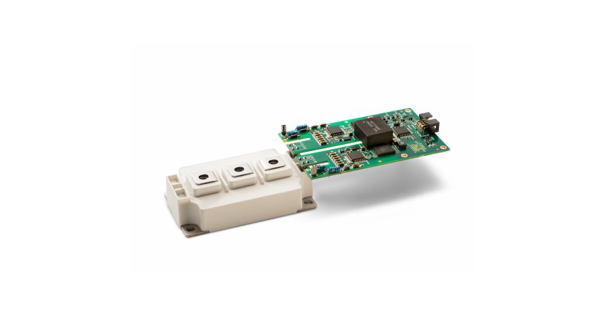
CISSOID, the leader in high temperature semiconductors for the most demanding markets, will present new High Temperature Gate Drivers, SiC MOSFET’s and IGBT Power Modules at PCIM 2019, the world’s leading exhibition and conference for power electronics, intelligent motion, renewable energy, and energy management.
The company is introducing a new Gate Driver board optimized for 62mm Silicon Carbide (SiC) MOSFET Power Modules rated at 125°C (Ta). This board, based on CISSOID HADES gate driver chipset, can also drive IGBT Power Modules whilst offering thermal headroom for the design of high density power converters in automotive and industrial applications. It enables high frequency (>100KHz) and fast SiC MOSFET’s switching (dV/dt>50KV/µs), improving efficiency and reducing size and weight of the power converters. The board is designed for harsh voltage environments supporting the drive of 1200V and 1700V power modules with isolation voltages up to 3600V (50Hz, 1min) and creepage distances of 14mm. Protection functions such as undervoltage lockout (UVLO), Active Miller Clamping (AMC) and Desaturation detection ensure the safe drive and reliable protection of the power module in case of fault events. “This new SiC Gate Driver board is the outcome of several years of developpement working with industry leaders in Automotive, Transportation and Aerospace markets. It combines CISSOID expertise in SiC Devices with our long experience in designing chips and electronic systems for harsh environments” says Etienne Vanzieleghem, CISSOID VP of Engineering.
In Nuremberg, CISSOID will also present new SiC MOSFET’s and IGBT Power Modules. A new discrete 1200V/40mOhms SiC MOSFET transistor is available in a TO-247 package and fully characterized from -55°C up to 175°C. This MOSFET features a drain-to-source On Resistance of 40mOhmsat 25°C (Tj) and 75mOhms at 175°C (Tj). Low switching turn-on and turn-off energies, respectively 1mJ and 0.4mJ, are making this device ideal for efficient and compact DC-DC converters, power inverters and battery chargers. The company will also present two 62mm 1200V IGBT Power Modules with 200A and 300A current rating.
CISSOID is also working on SiC MOSFET Power Modules that will be introduced in the coming months.
These new products show CISSOID commitment in providing a comprehensive offering of SiC-based solutions including transistors, modules and gate drivers to support industry transition towards highly efficient, lightweight and compact power conversion for use in new electric vehicles and renewable energies
says Dave Hutton, CISSOID CEO.
We are closely working with automotive OEM and Tier suppliers to customise our gate drivers for new SiC-based power inverters.
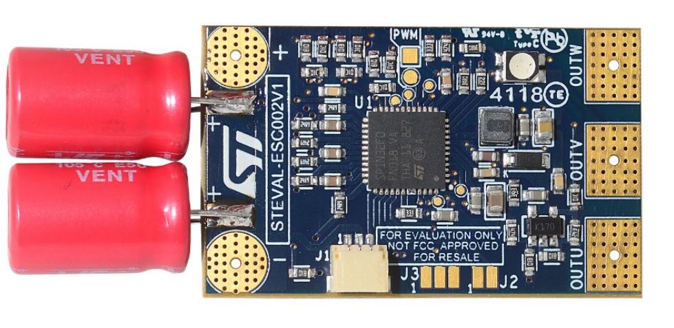
STMicroelectronics STEVAL-ESC002V1 Electronic Speed Controller Board is a very compact and ready to use Electronic Speed Controller (ESC) reference design. The board fits any small and light drone for racing or surveying purposes. It’s also highly suitable for any three-phase BLDC application requiring a small form factor, minimal BoM, and high-speed rotation performance. Together with the companion firmware package (STSW-ESC002V1), it represents a solution for sensorless voltage mode six-step driving.
The board includes the STSPIN32F0A advanced 3-phase brushless motor controller that embeds an STM32 Cortex®-M0® microcontroller, voltage regulators, signal conditioning circuitry and gate drivers in a small 7x7mm² QFN package. The power stage is based on the 2.8mΩ low resistance, high-speed TL140N6F7 MOSFETs, designed with STripFET™ F7 technology and able to deliver up to 20A of continuous current.
Key Features
Very compact and light design
Designed for sensorless six-step driving
2S to 6S LiPo battery pack
Output current up to 20 ARMS
Pre-configured firmware package (STSW-ESC002V1)
BEMF sensing through OpAmps embedded in STSPIN32F0A
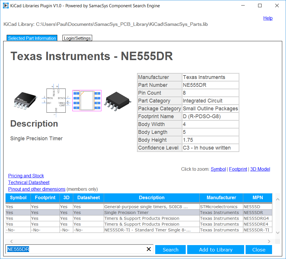
Digi-Key Electronics has announced the release of a new secondary KiCad library, known as the Digi-Key Partner Library, on GitHub. This is intended to be a supplement to the existing Digi-Key KiCad library released last year.
Whereas the previous library was developed and curated by Digi-Key’s Applications Engineering team, the Partner Library was created to allow manufacturers to submit their own symbols and footprints to be compiled into the Digi-Key format.
KiCad continues to grow in popularity as the open source alternative of robust EDA tools,
said Randall Restle, VP, Applications Engineering.
“The user community’s endorsement of Digi-Key’s atomic part library, which binds parts’ symbols to their correct printed circuit board footprints, datasheets, part numbers, and more, motivated us to develop the software tools to enable and motivate suppliers to develop their own KiCad design assets. Thereby, becoming a gold standard for such assets.
The initial rollout contains 45 parts submitted by TRINAMIC Motion Control GmbH and is set to expand as more suppliers engage in the program.
For more information about KiCad as well as the company’s full portfolio of EDA and design tools, visit https://www.digikey.com
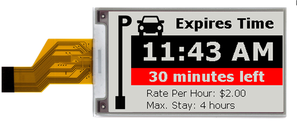
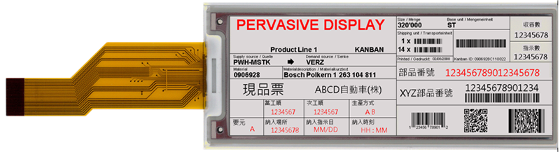
Pervasive Displays (PDi), a world leader in e-paper displays (EPDs), today announces the strengthening of its red tri-color EPD line-up with the launch of two new sizes of display. The 3.7-inch and wide-format 4.37-inch models can both render high-quality images and text in red, white and black.
The additional size options give product and service designers more flexibility when choosing displays, typically for use cases where there is no access to mains power. Unlike conventional TFT LCDs, e-paper displays only consume energy when you change what’s on the display, so maintaining a static image requires no energy at all. And because each screen update uses relatively little energy, e-paper displays can be powered using either a small battery or harvested energy.
This makes them a popular choice in a variety of applications where the contents of the display only needs updating sporadically such as logistics tags, ID and visitor badges, e-labels or IoT sensor node status screens.
With state-of-the-art driving waveform and respective pixel densities of 130 dpi (3.7-inch) and 117 dpi (4.37-inch), both can render sharp and detailed images and text. And because Pervasive Displays pre-programs key capabilities into the displays, they can be driven without consuming resource from the host controller.
Moreover, the displays’ slimline footprint, enabled in part by the built-in timing controller (Tcon), gives designers more space for other components, or the ability to minimize their overall product size.
Alchin Wang, CEO, Pervasive Displays, said:
Red EPDs provide a striking contrast that helps attract people’s attention and conveys critical information more quickly. Our red tri-color EPDs have been extremely popular, which is why we are expanding the range to give designers greater choice when selecting a display for their product.
And with speed-to-market a critical consideration for many customers, these displays are designed to be easy to integrate into end products, so they can be in customers’ hands as quickly as possible.
More information about both new red tri-color e-paper displays can be found on the Pervasive Displays website:
We have published quite a number of tutorials using different displays with the Arduino, with the most recent being the tutorial on displaying graphics on all kind of displays with Arduino. For today’s tutorial, we will look into achieving more with displays by implementing a menu based system with the Nokia 5110 LCD display and the Arduino. The menu is one of the easiest and most intuitive ways through which users interact with products that require navigation. From mobile phone to PCs, its applications are endless. Today we will explore how to add this cool feature to your Arduino project.
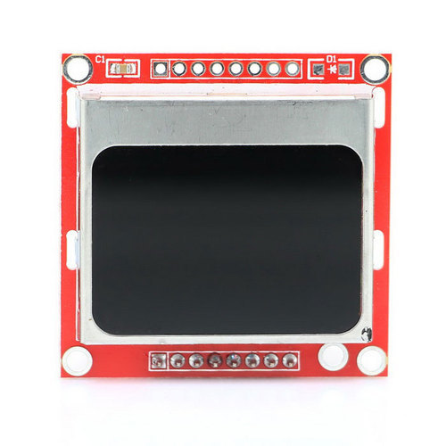
At the heart of today’s project is the Nokia 5110 LCD Display. The Nokia 5110 LCD is one of the most popular LCD display among makers. It was originally developed for use as a screen for cell phones and was used in lots of mobile phones during the 90’s. The display uses a low power CMOS LCD controller/driver, the PCD8544, which drives the 84×48px graphics display. In a normal state, the display consumes about 6 to 7mA which makes it quite ideal for low power devices. We have published quite a number of tutorials on this display that might help you understand how to drive such a display.
Menu on Nokia 5110 LCD display with Arduino – [Link]
We have published quite a number of tutorials using different displays with the Arduino, with the most recent being the tutorial on displaying graphics on all kind of displays with Arduino. For today’s tutorial, we will look into achieving more with displays by implementing a menu based system with the Nokia 5110 LCD display and the Arduino. The menu is one of the easiest and most intuitive ways through which users interact with products that require navigation. From mobile phone to PCs, its applications are endless. Today we will explore how to add this cool feature to your Arduino project.
At the heart of today’s project is the Nokia 5110 LCD Display. The Nokia 5110 LCD is one of the most popular LCD display among makers. It was originally developed for use as a screen for cell phones and was used in lots of mobile phones during the 90’s. The display uses a low power CMOS LCD controller/driver, the PCD8544, which drives the 84×48px graphics display. In a normal state, the display consumes about 6 to 7mA which makes it quite ideal for low power devices. We have published quite a number of tutorials on this display that might help you understand how to drive such a display.
Nokia 5110 LCD Display
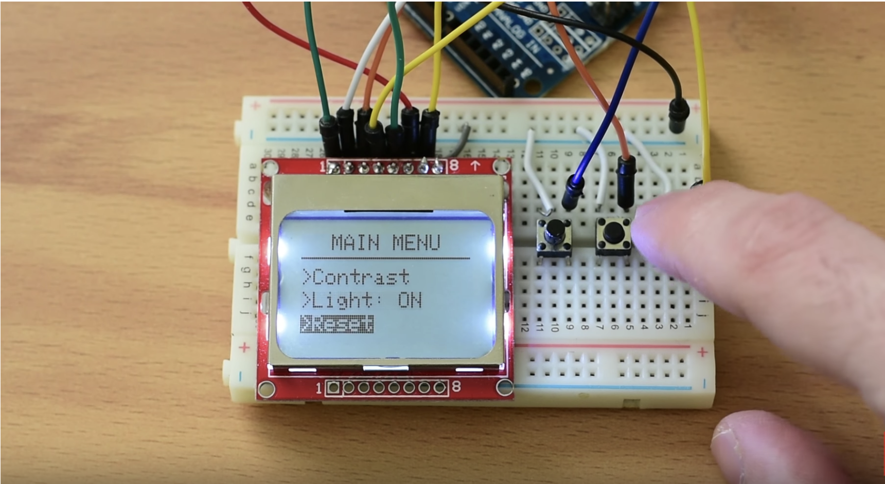
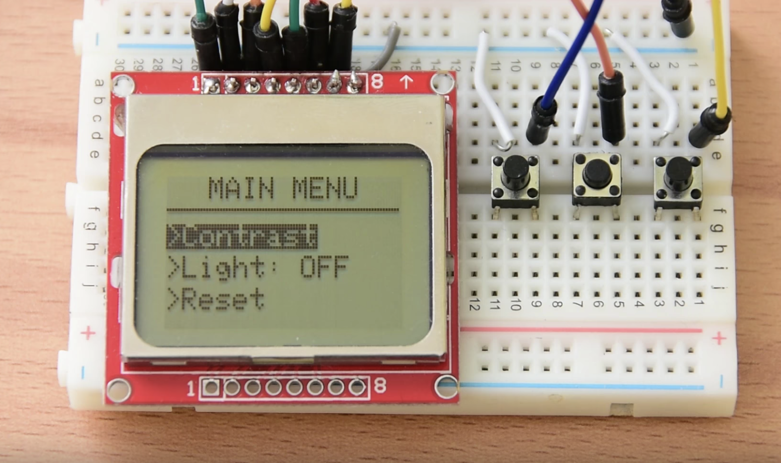
To showcase how to create the menu on a display with the Arduino, we will build a simple demo menu with three pages. To navigate through the menu, we will use 3x push buttons. The first to scroll up, the second to scroll down and the third one to select a highlighted option. The first screen/page of the menu will serve as the home page and will host the options that open the next two screens/pages. The second page will open after the first menu option on the homepage has been selected. Users will be able to change the contrast of the display using the up and down push buttons to increase or reduce it respectively. By pressing the select button, users will be able to go back to the home page. The second option on the homepage displays the third page, where users will be able to turn the backlight of the display on/off by pressing the select item button.
The Menu
Selecting the last option on the homepage does what it is labeled for, it clears all the previous settings for the contrast and backlight. This is a fun and interesting project which I believe can be very useful to anyone irrespective of your technical know-how level.
That’s it for introduction, Let’s now see how to build this project.
Required Components
The following components are required to build this project;
As usual, the exact components used for this tutorial can be bought via the link attached to each of them.
Schematics
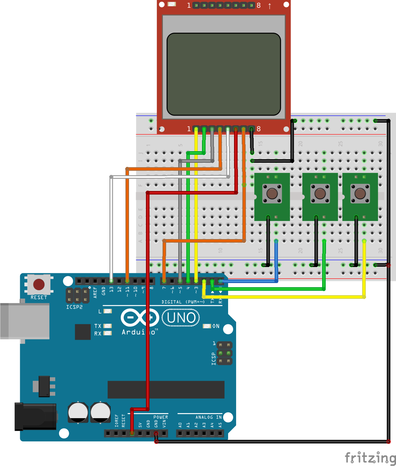
The schematics for this project is quite simple, connect the components as shown in the schematics below.
Schematics
To make the schematics easy to follow, a pin map of the connection between the Arduino Uno and the Nokia 5110, which isthe major component, is shown below.
LCD - Arduino
RST - D12
CE  - D11
DC  - D10
DIN - D9
CLK - D8
VCC - VCC
LIGHT - D7
GND - GND
Looking at the schematics, you will see that the push buttons are connected to the Arduino without the common pull-up or pull-down resistors. This is because we will use the Arduino’s internal pull-up resistor. You can read more about using pull-up/down resistors here. If you have any challenges understanding the concept, do reach out to me via the comment section.
With the connections all done, we can now proceed to the code for the project. It might be useful to go over the entire connection one more time to ensure everything is as it should be.
Code
To be fair, the code for today’s tutorial is a little bit complex and while I will do my best to break it down and ensure you understand the basics, it might take you building your own menu to fully grab the concept. The code for today is heavily dependent on two major libraries; The Adafruit GFX library and the Adafruit Nokia 5110 LCD Library. The Adafruit GFX library is probably one of the libraries we use the most in our tutorials. It makes it easy to display graphics and perform simple animations on supported displays. The Nokia 5110 LCD library, on the other hand, reduces the amount of work and code required to interact with the LCD.
We start the code as with other sketches by including all the libraries required for the project which in this case, are the Adafruit GFX and Nokia 5110 LCD libraries.
Next, we declare the pins to which the buttons are connected and also declare all the variables that we will use for the project. I believe the variable name provides enough insight into what each variable stands for.
boolean backlight = true;
int contrast=50;

int menuitem = 1;
int page = 1;

volatile boolean up = false;
volatile boolean down = false;
volatile boolean middle = false;

int downButtonState = 0;
int upButtonState = 0;
int selectButtonState = 0;
int lastDownButtonState = 0;
int lastSelectButtonState = 0;
int lastUpButtonState = 0;
Next, we write the void setup function. Here we declare all the pins to which the push buttons are connected as inputs and set digital pin 7 as output since the Light pin of the LCD is connected to it. This pin will be used to turn the backlight on/off later on.
After setting the pin modes, we initialize serial communication, initialize the screen, and set the screen contrast to 50 which serves as a default value (to be varied later using the menu buttons) and use the display.display() function to apply the changes.
Serial.begin(9600);

display.begin();
display.setContrast(contrast); //Set contrast to 50
display.clearDisplay();
display.display();
Next, we write the void loop function. We start the void loop function by calling the drawmenu() function which contains the code to create the menu objects on the screen.
void loop() {

 drawMenu();
Next, we read the buttons to check if any of them has been pressed.
The state of the buttons is then fed into a series of if-else statements which checks which button was pressed and which of the screens is currently being displayed to determine what action is done next. For instance, the first if statement checks if the menu is currently on page 1 and if the up button is pressed. If this is the case, it then checks the position of the menu cursor and adjusts it accordingly.
  if (up && page == 1 ) {
    up = false;
    menuitem--;
    if (menuitem==0)
    {
      menuitem=3;
    }
  }else if (up && page == 2 ) {
    up = false;
    contrast--;
    setContrast();
  }


  if (down && page == 1) {
    down = false;
    menuitem++;
    if (menuitem==4)
    {
      menuitem=1;
    }
  }else if (down && page == 2 ) {
    down = false;
    contrast++;
    setContrast();
  }


  if (middle) {
    middle = false;

    if (page == 1 && menuitem==2)
    {
      if (backlight)
      {
        backlight = false;
        turnBacklightOff();
        }
      else
      {
        backlight = true;
        turnBacklightOn();
       }
    }

    if(page == 1 && menuitem ==3)
    {
      resetDefaults();
    }


else if (page == 1 && menuitem==1) {
      page=2;
     }
else if (page == 2) {
      page=1;
     }
   }

  }
The remaining part of the sketch are the functions called within the loop function.
Go through the schematics one more time to ensure everything is connected as it should be, then connect the Arduino to your computer and upload the code. After a couple of seconds, you should see the menu displayed on the LCD and it should respond to the push buttons when pressed.
Demo
That’s it for today’s tutorial. Thanks for reading. While this is certainly not a project that is useful on its own, it will be a fantastic feature to add to your existing or new projects. Feel free to reach out via the comment section with your questions, suggestions, and comments on today’s tutorial. I will try to reply to them as soon as possible.
The video version of today’s tutorial is available on Youtube.
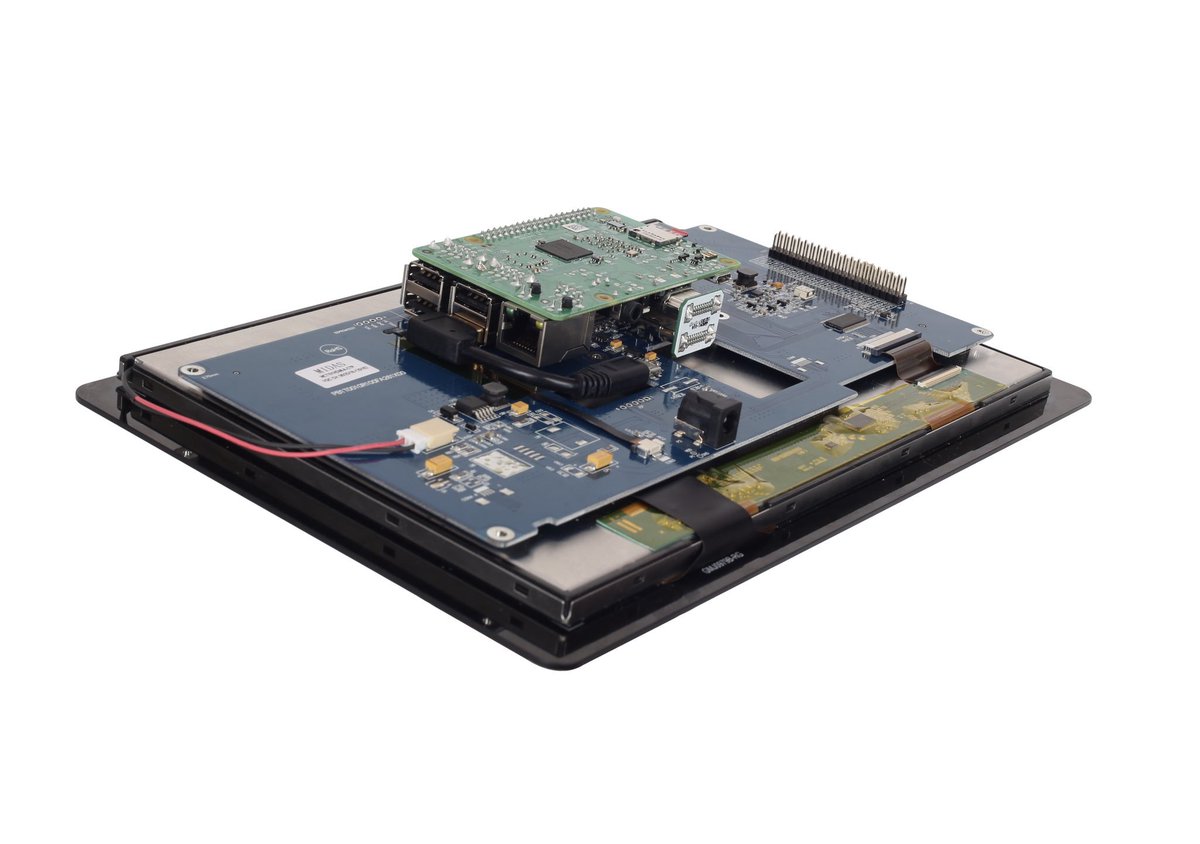
Display manufacturer and supplier, Midas Displays, has announced the introduction of a range of plug and play HDMI TFT display modules. The new displays are available in three different size and resolution options, have excellent brightness and contrast performance, and feature a fully integrated interface PCB.
With the addition of a Raspberry Pi SBC, the Midas Displays HDMI TFT display module becomes a fully functional, easy-to-use LCD monitor. The integrated interface PCB has a 40-pin GPIO interface and a standard 19-pin type-A HDMI interface connector, enabling direct connection of a Raspberry Pi SBC. The HDMI TFT modules can also easily be used with many other single board computers. These key features enable the HDMI TFT displays to be used with any external HDMI input source.
Midas Displays also supports interconnect solutions to enable enhanced connectivity of the Raspberry Pi to the HDMI TFT display module. A bespoke HDMI to HDMI interconnect board connects the HDMI output of the Raspberry Pi to the display mounted interface PCB, and a Type-A USB to Micro-B USB cable enables touch-screen functionality to be implemented.
All three display modules feature excellent optical performance which ensure bright, clear and concise images, high brightness white LED backlights, and a 16:9 Landscape aspect ratio. The operating temperature range of -20°C to +70°C enables reliable operation in extreme temperature environments.
For applications that require a dedicated graphical user interface, capacitive and resistive touch-screen options are available for all modules.
Paul Barton, technical director, Midas Displays said,
Our new HDMI TFT display module product range has been designed and produced to meet the needs of engineers and developers in the embedded and industrial market sectors. Our key goals were to provide a simple yet versatile display solution that could be used with an external HDMI input source. The industry standard video interface HDMI, is extensively supported on single board computers, personal computers, industrial equipment and many other embedded applications. Enabling a ‘plug and play’ HDMI TFT display in a range of sizes and resolutions, coupled with a choice of touch-screen options, provides designers with an easy-to-use display solution that is ideal for prototyping and product development.
The three HDMI TFT display modules currently available have the following attributes:
The 5.0-inch MCT050HDMI-A features WVGA resolution (800 x 480 pixels), a brightness of 500cd/m² and a contrast ratio of 500:1. The mechanical outline dimensions are 120.70mm (w) x 75.80mm (h) x 21.50mm (d) with an active display area of 108.0mm (w) x 64.8mm (h).
The 7.0-inch MCT070HDMI-B features WSVGA resolution (1024 x 600 pixels), a brightness of 600cd/m² and a contrast ratio of 800:1. The mechanical outline dimensions are 164.80mm (w) x 99.80mm (h) x 24.80mm (d) with an active display area of 154.21mm (w) x 85.92mm (h).
The 10.1-inch MCT101HDMI-A features WXGA resolution (1280 x 800 pixels), a brightness of 1100cd/m² and a contrast ration of 800:1. The mechanical outline dimensions are 230.56mm (w) x 155.01mm (h) x 25.60mm (d) with an active display area of 216.96mm (h) x 135.6mm (w).
The new Midas Displays 5.0″, 7.0″ and 10.1” HDMI TFT modules have outstanding optical performance and compact mechanical dimensions, enabling these displays to be used in a wide range of industrial equipment and embedded applications. The new HDMI TFT display modules are available directly from Midas Displays, and via Midas Displays sales channel partners and franchised distributors.
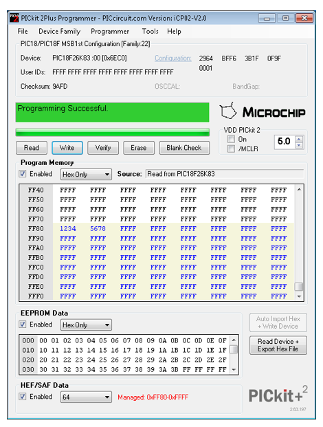
Microchip’sPICkit2 and PICkit3 are both In-Circuit Debugger/Programmers, designed for programming and debugging Microchip PIC microcontrollers (and occasionally EEPROMs).
The PICkit2 programmer was released back in 2005, and allowed the user to program and debug most of the 8 and 16 bit PIC microcontrollers and dsPIC controllers as well. Its successor, the PICkit3 programmer, was released some years later.
In 2009 and 2012, Microchip stopped providing support for the PICkit 2 and PICkit3 software , respectively. They released the source code for the Windows GUI software, making it possible for users to update and maintain it themselves. This resulted in the launch of the PICkitPlus software in 2018 by the PICkitPlus team.
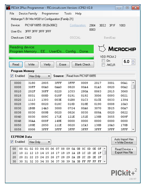
The PICkitPlus software is a total replacement for the original PICkit 2 and PICkit 3 software, designed to facilitate programming of any 8-bit PIC microcontroller using a supported programmer (either genuine or clone). In contrast to the original PICkit software, which doesn’t provide support for the newer 8-bit microcontrollers, PICkitPlus includes support for old chips and new chips alike.
PICkitPlus offers a new reliable alternative solution for Microchip PICkit2 and PICkit3 programmers to support users in programming their hex code into the PIC microcontroller by using this standalone software.
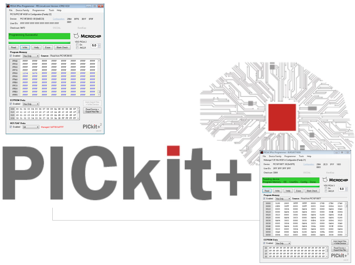
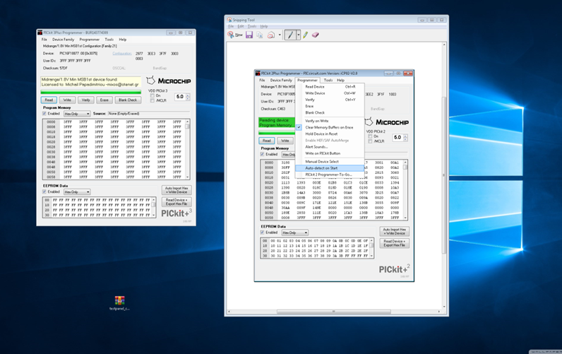
The PICkitPlus software comes in 3 main variants for the PICkit™ 2 and PICkit™ 3 applications called PICkit 2Plus, PICkit 3Plus, and PICkitCommandLine.
PICkit 3Plus Graphical user interface application. A specific solution for the PICkit™ 3 In-Circuit Debugger/Programmer and clones
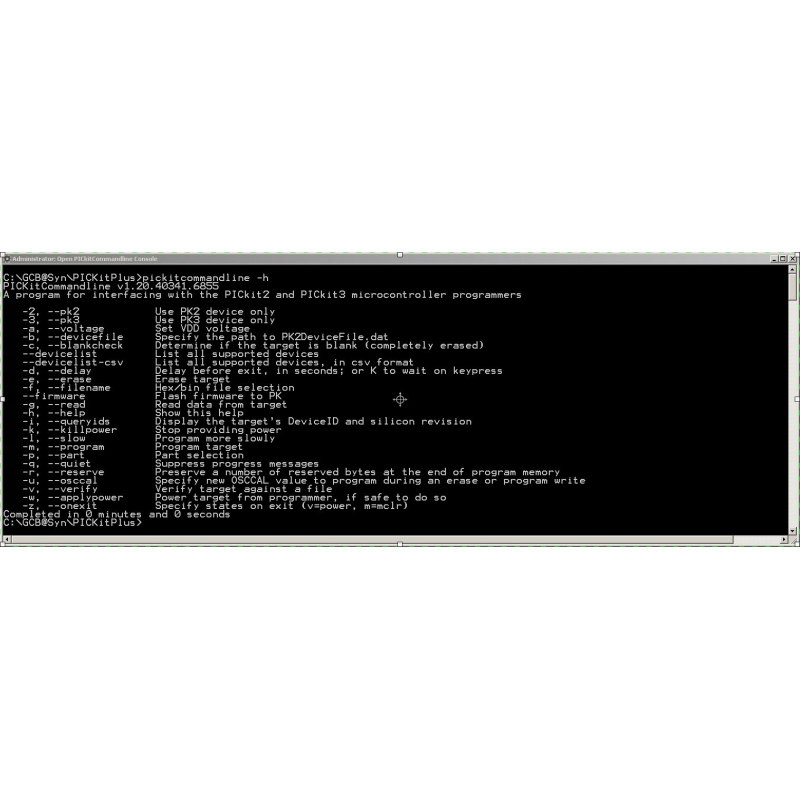
The PICkitPlus command line application supports both the PICkit2 and PICkit3 programmers and even potentially clones as well. It can run alone, but is mainly intended for use with Integrated Development Environments such as Great Cow BASIC. The PICkitPlus command line software does not support EEPROM chips; although the PICkitPlus GUI software does.
A common problem with using the old PICkit2 and PICkit3 software is their inability to work with very old or very new Microchip microcontrollers; but the PICkitPlus software comes with new programming protocols that support the various classes of Microchip’s 8-bit PIC microcontrollers. Not only does it support the currently released chips, but it also has an updated microcontroller database which helps to keep the software current with future microcontroller products. So if you are concerned about future compatibility, then PICkitPlus will be your best bet.
The old Microchip software has not been updated for many years, suffers from unreliability and lack of support. So, things failed to work, you were pretty much on your own. However, PICkitPlus comes with improved reliability and a better user interface; and since support is readily available you can always be sure to get help with any issues that might arise.
PICkitPlus Key features:
Standalone programming – no internet connection required
Supporting up to 932+ type of popular Flash PIC MCU, includes PIC10F, PIC12F, PIC16F, PIC18F, PIC24, PIC32, dsPIC30 and dsPIC33 family
Manages Microchip HEF and SAF memory
Programming CAN I/O Expander & KEELOQ series: MCP2502X/5X & HCSxx
Read and write operation for serial EEPROM 11LCxx, 24LCxx, 25LCxx and 93LCxx
Supported operating systems (32bit/64bit): Windows XP ,Windows Vista, Windows 7, Windows 8, Windows 10
New programming protocol support for new classes of 8-bit Microchip PIC microcontrollers
Updated and managed database for 8-bit Microchip PIC microcontroller
Improved user interface, help, guidance and direct access to the 8-bit Microchip PIC microcontroller database.
USB (Full speed 12 Mbits/s interface to host PC)
Supports low voltage (2.0v to 5.0v range) where supported by the programmer
Read/write program and data memory of microcontroller
Erase of program memory space with verification
Supports Low Voltage Programming (LVP) and High Voltage Programming (HVP).
Supports VDD-First and VPP-First programming modes.
PICkitPlus other features:
Safe Usage Enhancements:
Supports disabling part auto-detection to ensure circuits are not incorrectly powered-up
Supports selection of recently used microcontrollers
Supports Windows user profiles for ini files
Same microcontroller database across all three software components
Does not require any change to PICkit Operating system
Command Line Software:
All new solution to enable handling of capabilities
New command line structure and options
Same microcontroller database as GUI software
Automatic loading of PICKit Operating System
Improved voltage control during programming and post programming with appropriate safety checks
Supports IDEs with hold-on-exit
Write/Read and Verify options
Control power on and off independent of programming state
OSCCAL support
Meaningful exit error levels for IDE and batch file integration
Log files for IDE integration
HEF & SAF Operation:
Managing Microchip HEF (High Endurance Flash Memory) and SAF (Storage Area Flash) memory could not be easier with PICkitPlus
Providing read, write, erase, verify, save and import with ease
Obviates the need for cutting and slicing of hex files
Automatically merge HEF or SAF into source program
Bandgap Configuration:
The Bandgap is an adjustable voltage level used for Brown-out Detect (BOD)/low voltage
BOD and Bandgap can be enabled to track down short power spikes and resolve Brown-out situation
Simple setup by clicking the [BandGap] text
Fixing default bandgap error on PICkitPlus software when BOD is enabled
Target chips: PIC12F629, PIC12F675, PIC16F630 and PIC16F676
User Interface:
Simplification of user interface to improve stability and crashes
Check for latest version of the microcontroller database
Part type, revision and family displayed
Tooltips show memory size, eeprom size, HEF/SAF size and UserID location and type
Fast access to microcontroller databases listing
Improved handling of errors when using Auto Import Hex option
Improved color coding of events and language
Improved handling of sound events (they now work…)
Installer:
Installer shows version of software and microcontroller database
Supports from Windows XP all the way to Windows 10
Contains help files, list of supported microcontrollers and user guides
Integration guides for popular IDEs
Introduction Video
PICkitPlus provides support for over 932 types of popular Flash PIC MCU including the likes of PIC10F, PIC12F, PIC16F, PIC18F, PIC24, PIC32, dsPIC30, and dsPIC33 family. Managing of the Microchip HEF and SAF memory just become easier with support for reading, write, erase, verify, save and imports. Read and write operation for serial EEPROM 11LCxx, 24LCxx, 25LCxx and 93LCxx is available. It can also easily integrate with popular IDEs. Programming of CAN I/O Expander & KEELOQ series: MCP2502X/5X &HCSxx are also supported.
PICkitPlus supports Low-Voltage (2v to 6v) Programming (LVP), and High-Voltage (9v to 12v) Programming (HVP). Brown-out Detect and Bandgap can be enabled to track down short power spikes and resolve Brown-out situation.
Currently, OS support is limited to Windows 10, Windows 8.1, Windows 8.0, Windows 7 and Windows XP; although Anobium plans to add support for Linux and MacOS in due course.
More information about the features of the PICkitPlus is available www.pickitplus.co.uk, and the PICkitPlus software is also available for purchase from Piccircuit for $12 or direct from www.pickitplus.co.uk for the complete package.
The advent of smaller, lower-cost and lower-powered pressure sensors has generated a new wave of innovation, increasing efficiency and performance both in the sensors themselves and their applications. The worldwide pressure sensor market is set to grow to $11.4 billion by 2024, as demand for these technologies increases.
Selecting the right sensor technology for your application from the wide variety now available on the market can be challenging. So we’ve created The Design Engineer’s Guide to Pressure Sensorsto help you understand the types of sensors in common use, their operating principles, and their modes of use (absolute, gauge, or differential).
Whether you’ve designed with pressure sensors before or not, this field guide is intended to provide a comprehensive overview of the technologies, insight into the various applications, and assistance in finding the sensor that’s right for your design.