Over the last few articles, we have covered the use of ESP8266boards for building several WiFi based projects. For today’s tutorial, we will look at it’s recently released successor; the ESP32.
As mentioned in previous tutorials, ESP-12e module popularly referred as the nodeMCU came at a time where makers were struggling with the difficulties around the use of the ESP-01 modules. The ESP-01 modules were not breadboard compatible, had power issues, and could barely be used in a standalone application where more than two GPIOs are required. The NodeMCU solved all these issues adding additional features and it immediately became a darling of the maker community. However, the ESP8266 equally had its own limitations and like every good product, there was a need to improve it. This improvement came in the form of the ESP32.
Over the last few articles, we have covered the use of ESP8266boards for building several WiFi based projects. For today’s tutorial, we will look at it’s recently released successor; the ESP32.
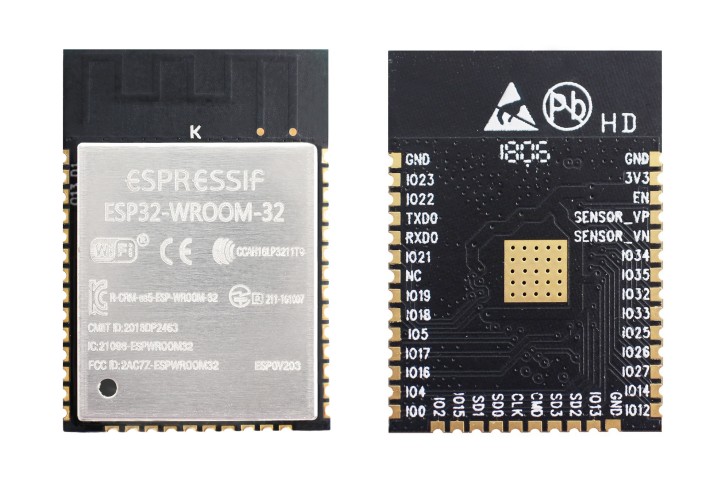
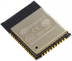
ESP32 Module
As mentioned in previous tutorials, ESP-12e module popularly referred as the nodeMCU came at a time where makers were struggling with the difficulties around the use of the ESP-01 modules. The ESP-01 modules were not breadboard compatible, had power issues, and could barely be used in a standalone application where more than two GPIOs are required. The NodeMCU solved all these issues adding additional features and it immediately became a darling of the maker community. However, the ESP8266 equally had its own limitations and like every good product, there was a need to improve it. This improvement came in the form of the ESP32.
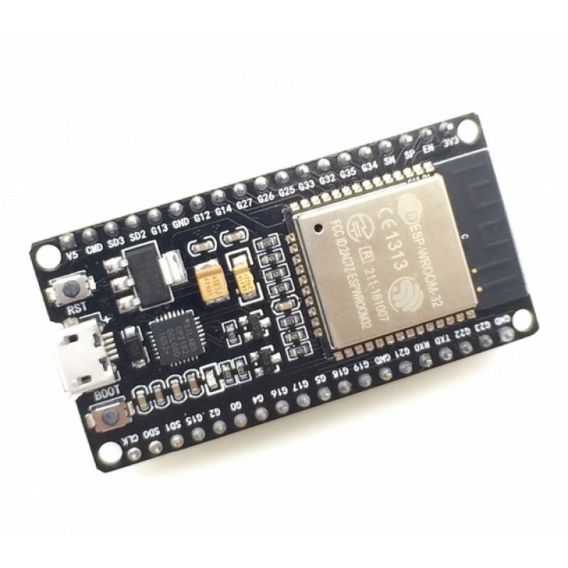
DOIT DEVKIT V1 ESP32 Based Board
The ESP32 is way advanced compared to the ESP-12e. Among several features, the ESP32 packs a CPU core, a faster Wi-Fi, more GPIOs (especially increased analog pins that we all desired), supports Bluetooth 4.2 and Bluetooth low energy. The board also comes with touch-sensitive pins, alongside a built-in hall effect and temperature sensors. While both boards are quite cheap, the ESP32 ($6 – $12) costs slightly more than the ESP-12e ($3-$6).
The table below provides a more detailed comparison between the two modules.
ESP8266
ESP32
Microcontroller
Xtensa Single-core 32-bit L106
Xtensa Dual-Core 32-bit LX6 with 600 DMIPS
Wi-Fi Module
HT20
HT40
Bluetooth Support
X
Bluetooth 4.2 and BLE
Frequency
80 MHz
160 MHz
SRAM Availability
X
✓
Flash Availability
X
✓
GPIO
17
36
Hardware /Software PWM
None / 8 channels
None / 16 channels
SPI/I2C/I2S/UART
2/1/2/2
4/2/2/2
ADC Resolution
10-bit
12-bit
CAN Support
X
✓
Ethernet MAC Interface
X
✓
Touch Sensor
X
✓
Temperature Sensor
X
✓
Hall effect sensor
X
✓
Working Temperature
-40ºC to 125ºC
-40ºC to 125ºC
Today’s tutorial will not only provide a comparison between these boards, but it will also show you how to put the ESP32 board to use. We will look at setting up the ESP32 module for programming with the Arduino IDE and we will run the Arduino blink example on the board. This will allow you to setup all that is needed for the exciting projects we will build with this new board over the next few tutorials.
Required Components
The following components are required for this tutorial;
ESP32 based development board ( I will be using the DOIT DEVKIT V1 board)
Breadboard
Jumper wires.
100 Ohms resistor
LED
The tutorial should work with any ESP32 based board. The choice of the DOIT DevKIT V1 is as a result of its availability and general popularity.
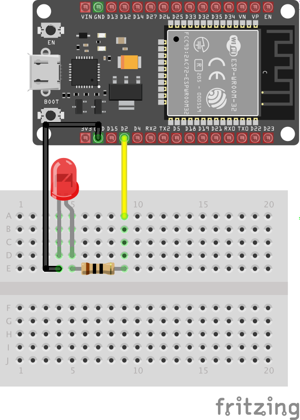
Schematics
We will connect a LED to the ESP32 such as that the LED blinks as the popular blink example.
Connect the LED to the ESP32 as shown below.
Schematics
Programming the ESP32
Like the ESP-12e modules and boards, the ESP32 modules and boards can also be programmed with LUA on the ESPlorer IDE or with C/C++ on the Arduino IDE. However, like the ESP8266, we will need to install the ESP32 core and board files on the Arduino IDE before it can be used to upload code to the ESP32.
The process of installing the ESP32 core on the Arduino IDE is similar to the one we followed to install the ESP8266 Arduino Core.Follow the steps below:
– Open the preferences window from the Arduino IDE. Go to File > Preferences
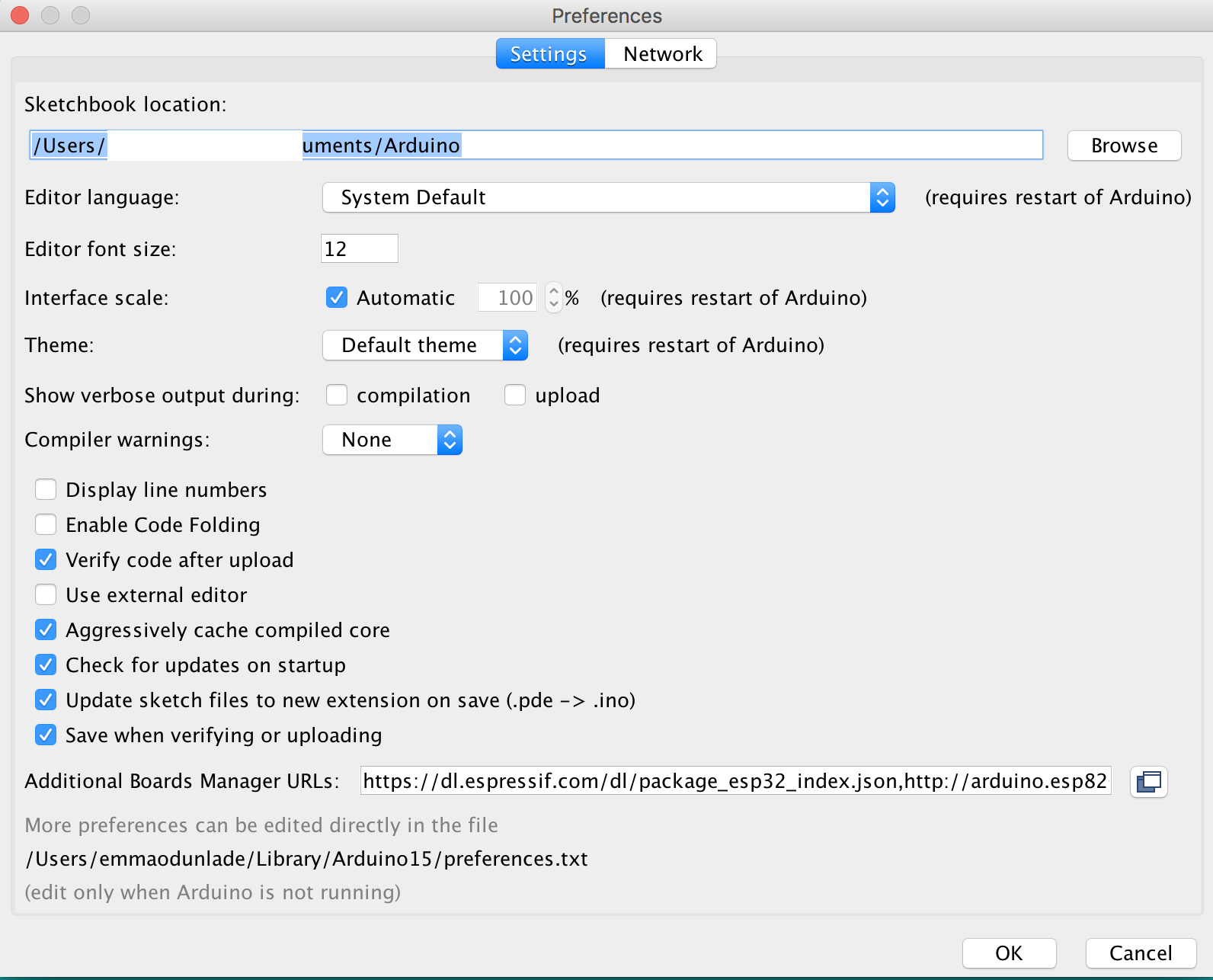
– On the preferences window, locate the “Additional Board Manager URLs” text box and enter https://dl.espressif.com/dl/package_esp32_index.json into the field as shown below. As you may have other URLs there already, separate the URLs from each other using a comma (“,”) and click OK when done.
Insert URL
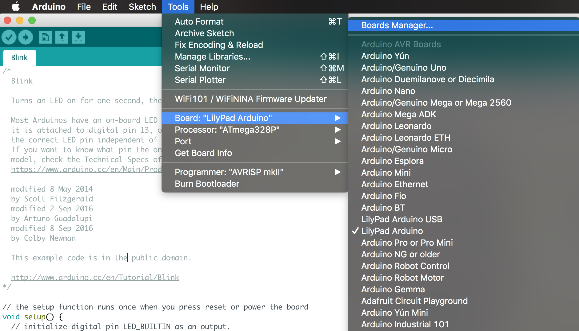
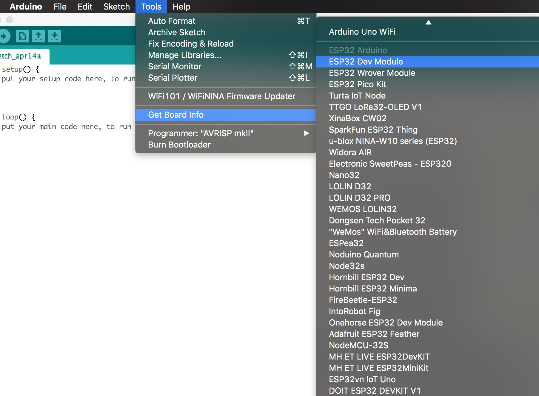
– Next, open the Arduino board manager. Go to tools > Boards > Boards manager
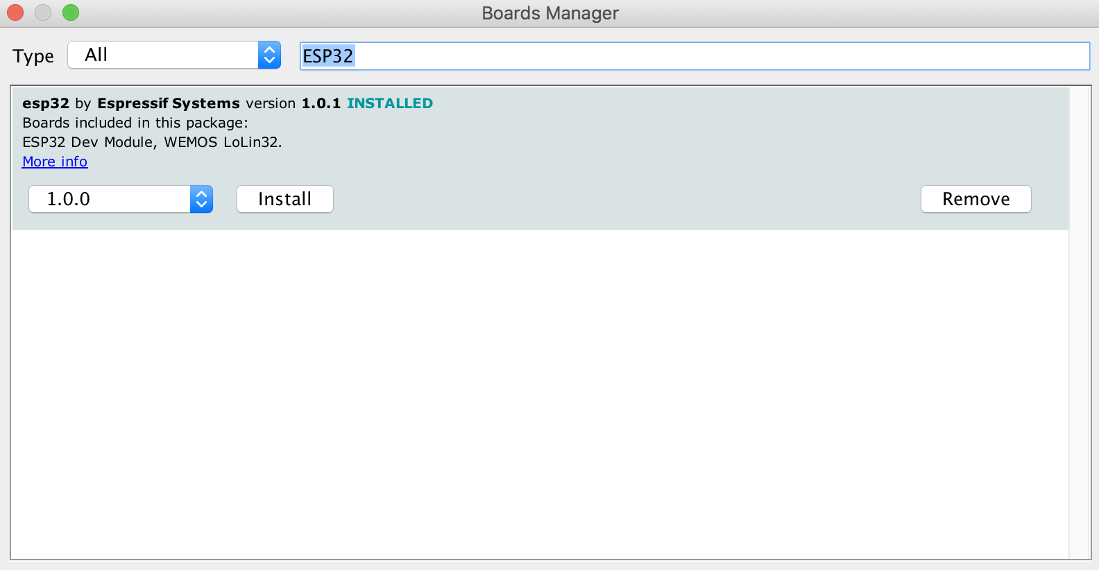
– When the board manager opens up, enter ESP32 into the search bar and scroll to the bottom, you will see “ESP32 by Espressif systems”, click on install.
Click on Install
With that done, you should now see quite a number of ESP32 based boards under the Arduino Board list.
ESP32 Boards listed under the Board Manager
You should also be able to see quite a number of libraries installed alongside the core. The libraries are pretty extensive and should cover for most of the tasks you might need to do with the ESP32.
At this point, it is important to note that the ESP32 is completely different from the ESP8266, and the code for ESP8266 based projects will not work directly on the ESP32 until necessary modifications are made. Also, most of ESP8266 compatible libraries are not compatible with the ESP32 so quite a number of modification may be required. This is one of the downsides to building projects based on the ESP32.
With that done, we can now write the code for the demo project.
Code
The code for this tutorial is the blink example we are all familiar with.
Load the example by going to tools and selecting your ESP32 board (Mine is the DOIT ESP32 DEVKIT V1) then go to file > examples > built-in examples > basics > blink. This will open the blink example.
While I believe most people understand the blink code, to stick to the tradition, I will do a brief explanation.
We will make a slight modification to the code since we connected our LED to a pin different from the one on which the ESP32’s built-in LED is located. We start by declaring that pin.
int LED = 2;
Next is the void setup() function. All we need to do here is set the pin to which our led is connected as an output.
void setup()
{
  pinMode (LED, OUTPUT);
}
Lastly, the void loop function. Here we create lines of code to turn the LED on and off after certain intervals to create the blink effect.
Connect the LED to the DOIT DEVKIT as illustrated in the schematics above and then connect the board to your computer and upload the code. You should see the LED blinking. It’s important to note that most ESP32 based boards have the “boot” button which must be pressed once the code is uploaded to the board.
That’s it for this tutorial guys. Over the next few tutorials, we will build more interesting and challenging projects using the WiFi and Bluetooth functionalities of the ESP32.Do reach out via the comment section if you have any question(s).
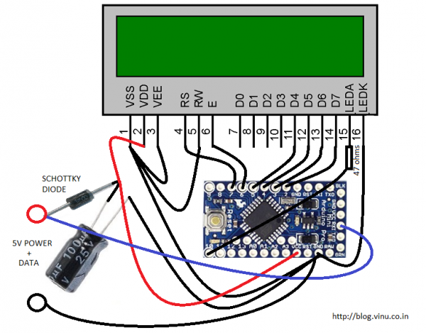
Vinod blogged about a 16×2 LCD with data over power line:
Then I just thought why even 1 wire for data? Because we can easily multiplex the 1 wire data line with the Vcc line by keeping a diode + capacitor combination towards the LCD power supply pin. I am using an arduino board to do the serial to parallel conversion + some packet parsing and lcd backlight brightness control. I am not a huge fan of Arduino but for this simple proof of concept, I don’t want to bring out a Makefile folder with muliple files. I picked the Arduino UART RX as the serial receiver. RX pin is connected directly to the input Vcc, but before the schottky diode.
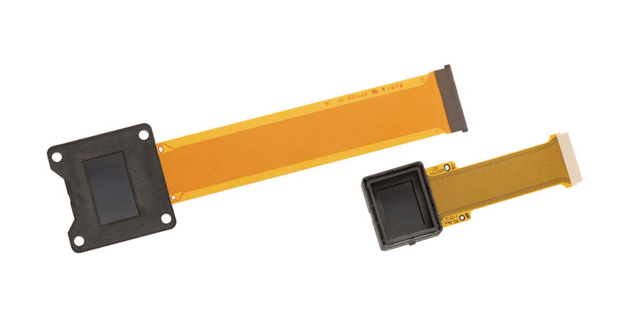
Sony Corporation today announced the upcoming release of the ECX339AOLEDMicrodisplay featuring UXGA (1600 x 1200 resolution), the highest in class for a 0.5-type. This product achieves the world’s smallest pixel pitch of 6.3μm by leveraging Sony’s OLED display technology and miniaturization technology, enabling a resolution 1.6x higher than the previous model1. By employing a new drive circuit design that operates on half the voltage of the previous model1, the new product achieves the same level of low-power operation as its predecessor but with much higher resolution. When paired with Sony’s original driving system2, a frame rate up to 240 fps is supported—double that of previous product1.
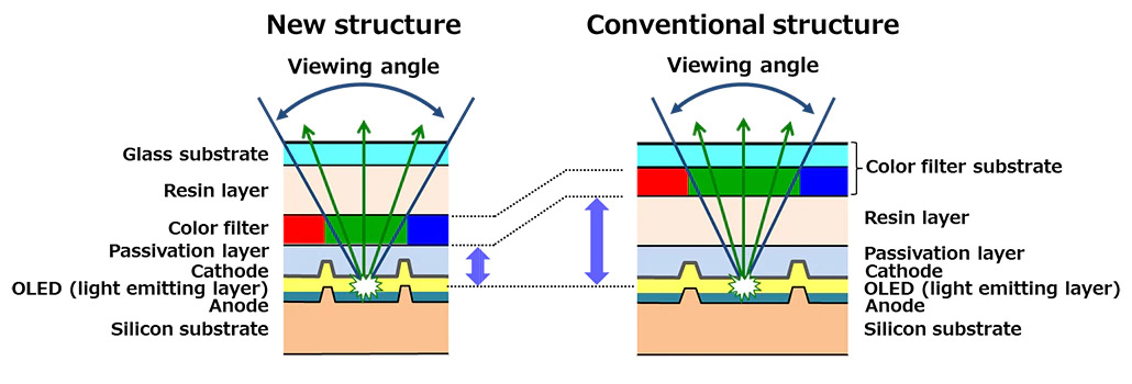
Enhancing the resolution on microdisplays has traditionally presented problems such as deteriorating image quality due to decreased pixel pitch and inferior viewing angle properties. The new product features optimized transistors layout and process to address uneven characteristics and loss of withstand voltage, the issues associated with transistor miniaturization. The Sony original variation compensation circuit also enhances picture quality. Additionally, the color filter is deposited directly on the silicon substrate, reducing its distance from the light emitting layer, and the filter’s color array has been modified. This helps to secure the viewing angle properties while achieving high resolution.
Comparison of images on OLED Microdisplays. New product (UXGA, left) and previous product (QVGA, right)
OLED Microdisplays are widely used in digital camera electronic viewfinders (EVF) for their superior high contrast, high color gamut, and high-speed responsiveness. Sony, having achieved this high resolution and high frame rate, now offers even more realistic image display and accurate capture of subjects for use in high-end cameras that demand extremely high image quality.
Going forward, Sony expects this high-definition OLED Microdisplay to be employed in a diverse range of fields and applications such as AR (augmented reality) and VR (virtual reality) head-mounted displays.
Main Features
Measures to secure viewing angle even with smaller pixel pitch New product (UXGA, left) and previous product (QVGA, right)
High-resolution UXGA in a 0.5-type – The new product has achieved the world’s smallest pixel pitch of 6.3μm by leveraging Sony’s proprietary OLED display technology and miniaturization technology, and has superior resolution 1.6x higher than the previous model*1. Generally, transistor miniaturization results in characteristic variation and reduced withstand voltage. This product uses a Sony original compensation circuit and optimized layouts and process for each individual transistor to address these adverse effects. Furthermore, the color filter is deposited directly on the silicon substrate, reducing its distance from the light emitting layer, and the filter’s color array has been modified to secure the viewing angle properties while achieving high resolution.
High-speed frame rate – A new drive circuit design supports a high frame rate of up to 240 fps*2, nearly double that of its predecessor*1. This has made it possible to capture fast-moving subjects in the viewfinder with higher accuracy, so users will not miss a photo opportunity, delivering a more comfortable shooting experience. In head-mounted display devices, this will help to improve image delay issue for items superimposed on real-world vision of AR and to avoid motion sickness during usage of these kinds of devices.
Low power consumption – By employing newly-designed peripheral circuits that operate on half the voltage of previous model*1, the new product delivers the same low-power operation as its predecessor when operating at the same frame rate, despite the nearly 1.6x increase in the number of pixels.
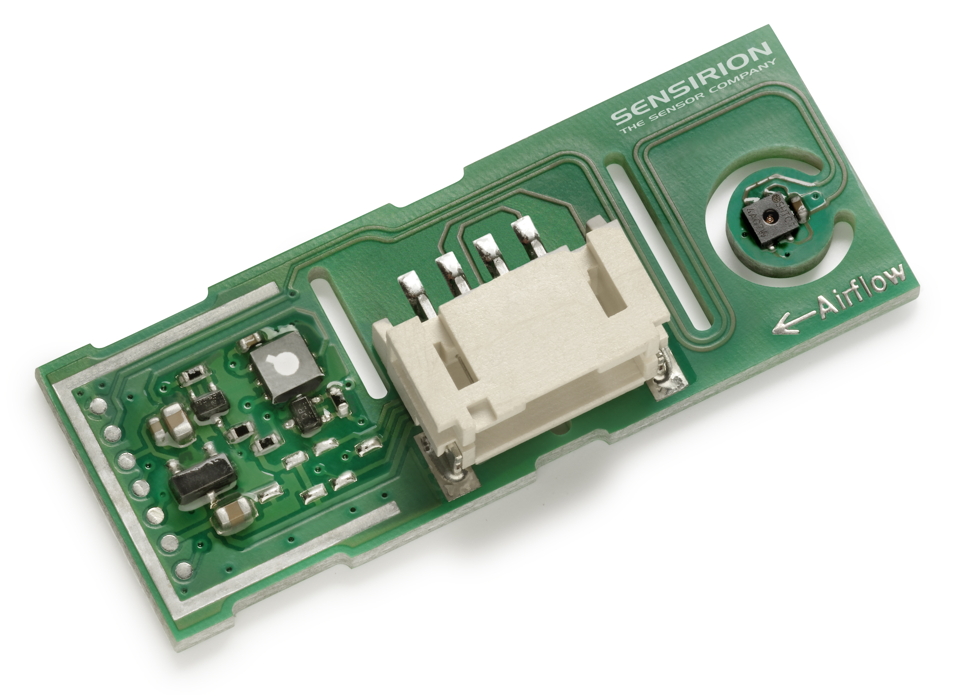
The solution for gas, humidity and temperature sensing remotely from the main control board is now available worldwide through Sensirion’s distribution network.
Sensirion, the expert in environmental sensing, now offers a multi-gas, humidity and temperature module, the SVM30. The module facilitates product development and sensor integration while at the same time offering great flexibility for product design. The SVM30 is especially suitable for customers that prioritize lean development and products, and perfectly appropriate for small and medium-sized companies. Based on Sensirion’s experience and expertise in environmental sensing, the SVM30 is optimized for easy design-in and sensing performance. The SVM30 is a multi-gas, humidity and temperature sensor combo module containing an SGP30 gas sensor as well as an SHTC1 humidity and temperature sensor.
The SGP30 gas sensor combines multiple metal-oxide sensing elements – the pixels – on one chip, thereby offering the possibility of measuring a total VOC signal (tVOC) and a CO2 equivalent signal (CO2eq) with one single sensor chip. The SVM30 also offers calibrated air quality output signals as well as compensation of humidity cross-sensitivity. The gas sensing element features unmatched robustness against contamination by siloxanes present in real-world applications, enabling unique long-term stability and low drift. Furthermore, the integrated SHTC1 humidity and temperature sensor covers a humidity measurement range of 0 to 100% relative humidity (RH) and a temperature measurement range of -20 to 85°C with a typical accuracy of ±5% RH and ±1°C. The gas, humidity and temperature sensor components are designed with Sensirion’s proven CMOSens® Technology. This technology offers a complete sensor system on a single chip, including the sensing elements, analog and digital signal processing, A/D converter, calibration and data memory as well as a digital communication interface supporting the I2C standard mode. Sensirion’s state-of-the-art production process, including full calibration and testing of the sensors, guarantees high reproducibility and reliability.
The main application for the SVM30 sensor combo module is air purifiers, but it is also optimally suited for HVAC and other appliance products.
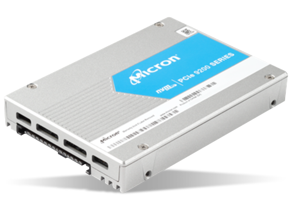
Micron 9200 NVMe™ Solid State Drives (SSDs) comes under Micron’s flagship performance product line and the second generation of NVMe drives. These SSDs utilize Gen3 PCIe interface, innovative non-volatile memory express protocol, and Micron’s high-speed NAND to provide high-throughput and IOPS, low-latency, and consistent quality of service. The 9200 SSDs are available in high-capacities up to 11TBs and incorporates FlexPro™ firmware architecture to actively tune the capacity to optimize drive performance and endurance. The reliability assurance measures include Cyclic Redundancy Checks (CRC), end-to-end data path protection, capacitor-backed power loss protection, and Micron’s extensive validation, quality, and reliability testing. The 9200 NVMe SSDs also feature thermal monitoring and protection, SMART attributes for status polling and SMBus for out-of-band management. These SSDs are ideally used in big data, high-performance computing, virtualization, and database management.
The Micron 9200 includes three endurance classes:
Micron 9200 PRO: For read-centric use at roughly 1 Drive Writes Per Day (DWPD) with 1.92TB, 3.84TB, and 7.68TB capacities.
Micron 9200 MAX: For mixed-use workloads at about 3 DWPD with 1.6TB, 3.2TB, and 6.4TB capacities.
Micron 9200 ECO: For less than 1 DWPD with 8TB and 11TB capacities.
Features
Micron® 3D NAND Flash
PCI Express® (PCIe®) Gen3 ×4
NVM Express™ (NVMe™) Specification 1.2
3 endurance classes with capacities:
9200 ECO: 8TB and 11TB
9200 PRO: 1.92TB, 3.84TB, and 7.68TB
9200 MAX: 1.6TB, 3.2TB, and 6.4TB
Endurance (total bytes written):
1.6TB: Up to 17.5PB
1.92TB: Up to 16.8PB
3.2TB: Up to 29.8PB
3.84TB: Up to 29.4PB
6.4TB: Up to 59.5PB
7.68TB: Up to 58.8PB
8.0TB: Up to 58.4PB
11.0TB: Up to 80.3PB
Industry-standard 512-byte and 4096-byte sector size support
Power: <8W idle, 25W power limited, or unlimited
Surprise Insertion/Surprise Removal (SISR) and hot-plug capable
Power-backed cache
Steady state performance (varies by capacity and form factor):
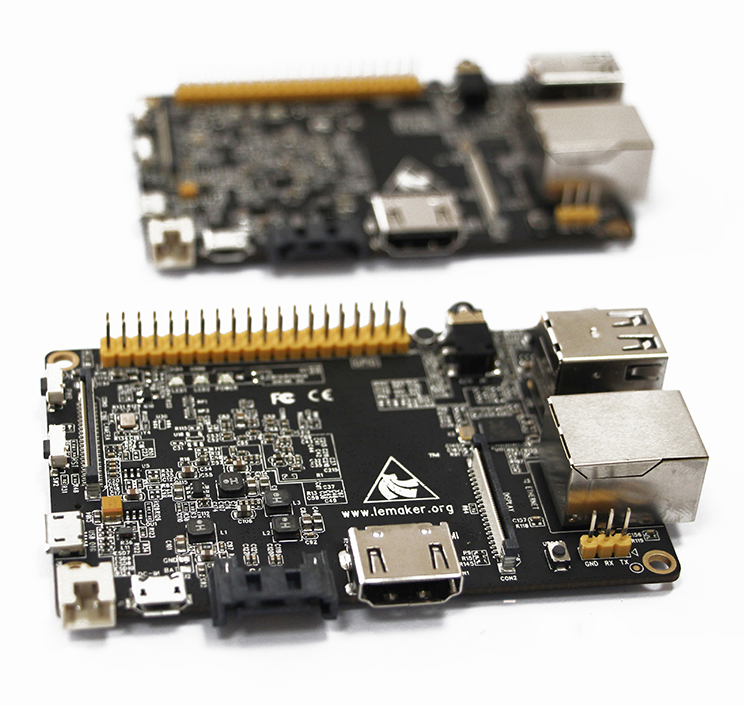
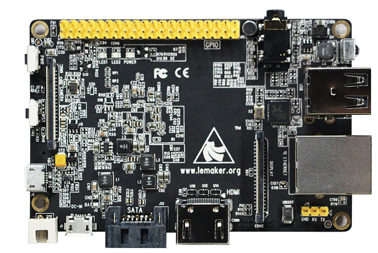
The Banana Pi Pro Computer Board comes with ARM Cortex-A7 Dual-Core CPU @ 1.0GHz. It supports multi-channel HD display. It has on board WiFi network of 802.11 b/g/n and parallel 8-bit camera interface.
Banana Pro™ is an updated version of Banana Pi™ designed by the LeMaker Team. Try Banana Pro™ today and take advantage of the many enhanced features.
Banana Pro™ is compatible with many Linux-based operating system and has many distributions specially developed for Banana Pi™ Hardware. Some of these distributions include Lubuntu, Android, Debian, Bananian, Berryboot, OpenSuse, Scratch, Fedora, Gentoo, Open MediaVault, OpenWRT. Banana Pro™ also supports the BSD system.
Banana Pro™ has a wide selection of home applications including: Building a low-cost computer, Servers (for Multimedia, Minecraft or other home servers), Video Game Emulators, Home Security Cameras and more.
Banana Pro™ is an excellent educational learning tool that can be used for many projects including: building Multimedia projects,Robots, Arduino applications or Computer Programming with many popular programming languages available including Scratch (a drag and drop programming language for people beginning to learn how to code).
Features
Display:
Composite video (PAL and NTSC) (via 3.5 mm TRRS jack shared with audio out)
LVDS/RGB/CPU display interface (DSI) for raw LCD panels
11 HDMI resolutions from 640×480 to 1920×1080 plus various PAL and NTSC standards
HD H.264 2160p video decoding
Video:
Mutil-format FHD video decoding, including Mpeg1/2, Mpeg4, H.263, H.264, etc
H.264 high profile 1080p@30fps or 720p@60fps encoding
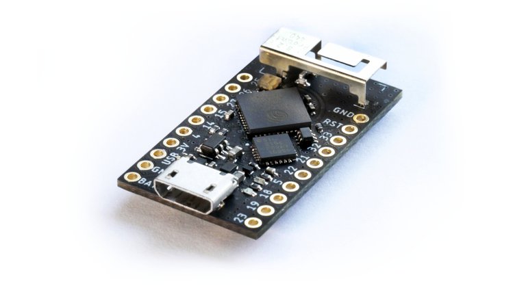
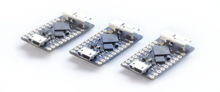
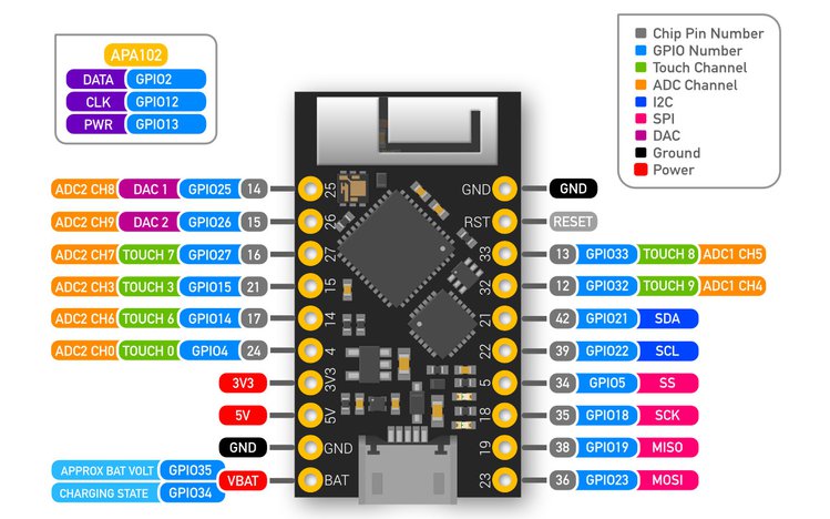
TinyPICO is the world’s smallest, fully featured ESP32 development board, designed to give access to the power of the ESP32’s dual core 240 MHz and internet connectivity, in a package smaller than your thumb! The designers of the board wasn’t satisfied with the existing ESP32 boards that compromised some of it’s features, so they decided to build TinyPICO by adding a set of new capabilities.
Features & Specifications
32-bit dual core processor operating at 240 MHz
2.4 GHz Wi-Fi – 802.11b/g/n
Bluetooth BLE 4.2
4 MB SPI flash
4 MB extra PSRAM
APA102 RGB LED
USB + serial/UART for programming
700 mA 3.3 V LDO Regulator
LiPo battery management
Optimised power path for low power battery usage
JST pads on the bottom supports PH & MicroBlade connectors for a battery
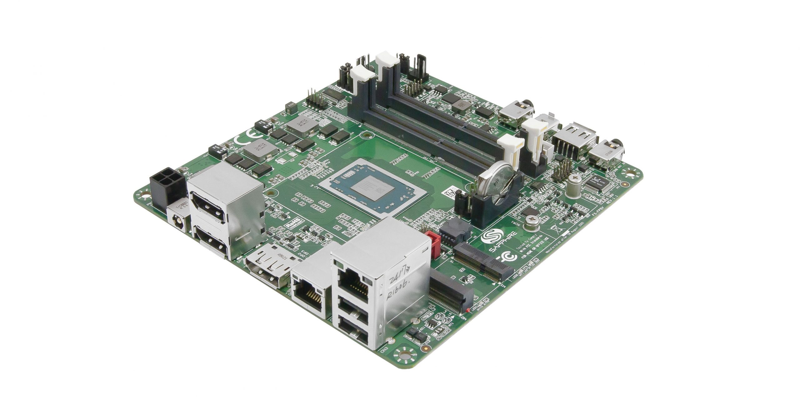
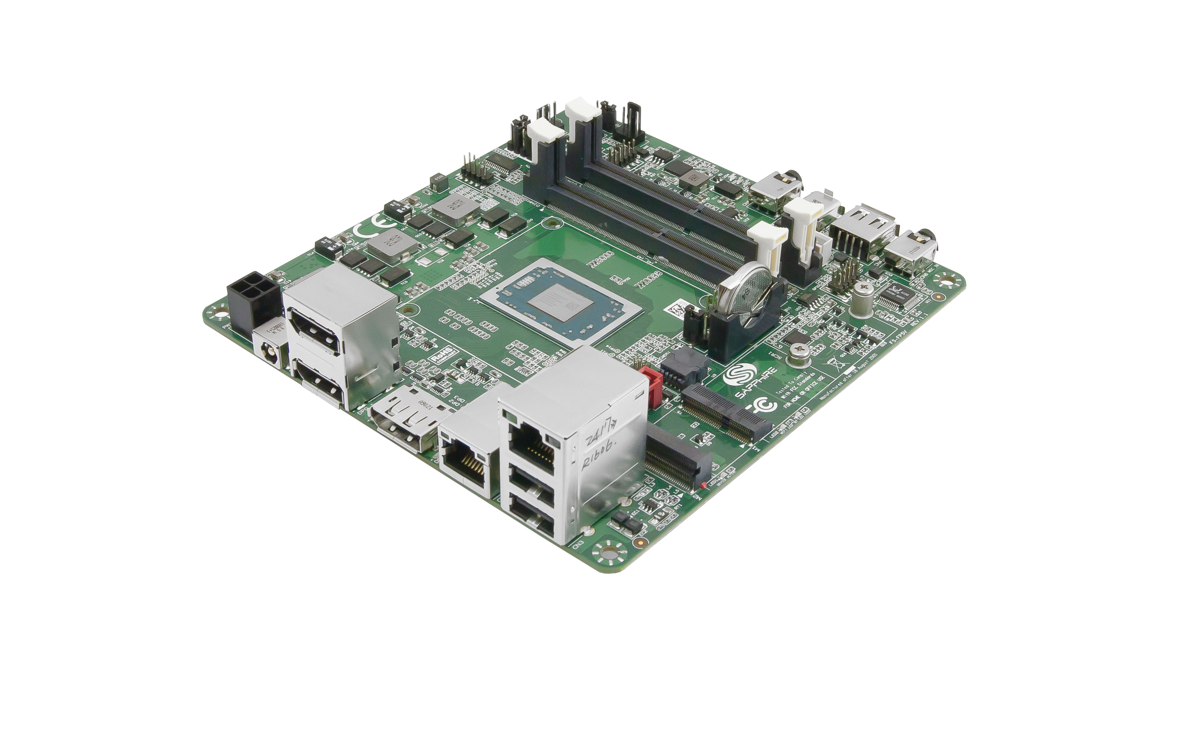
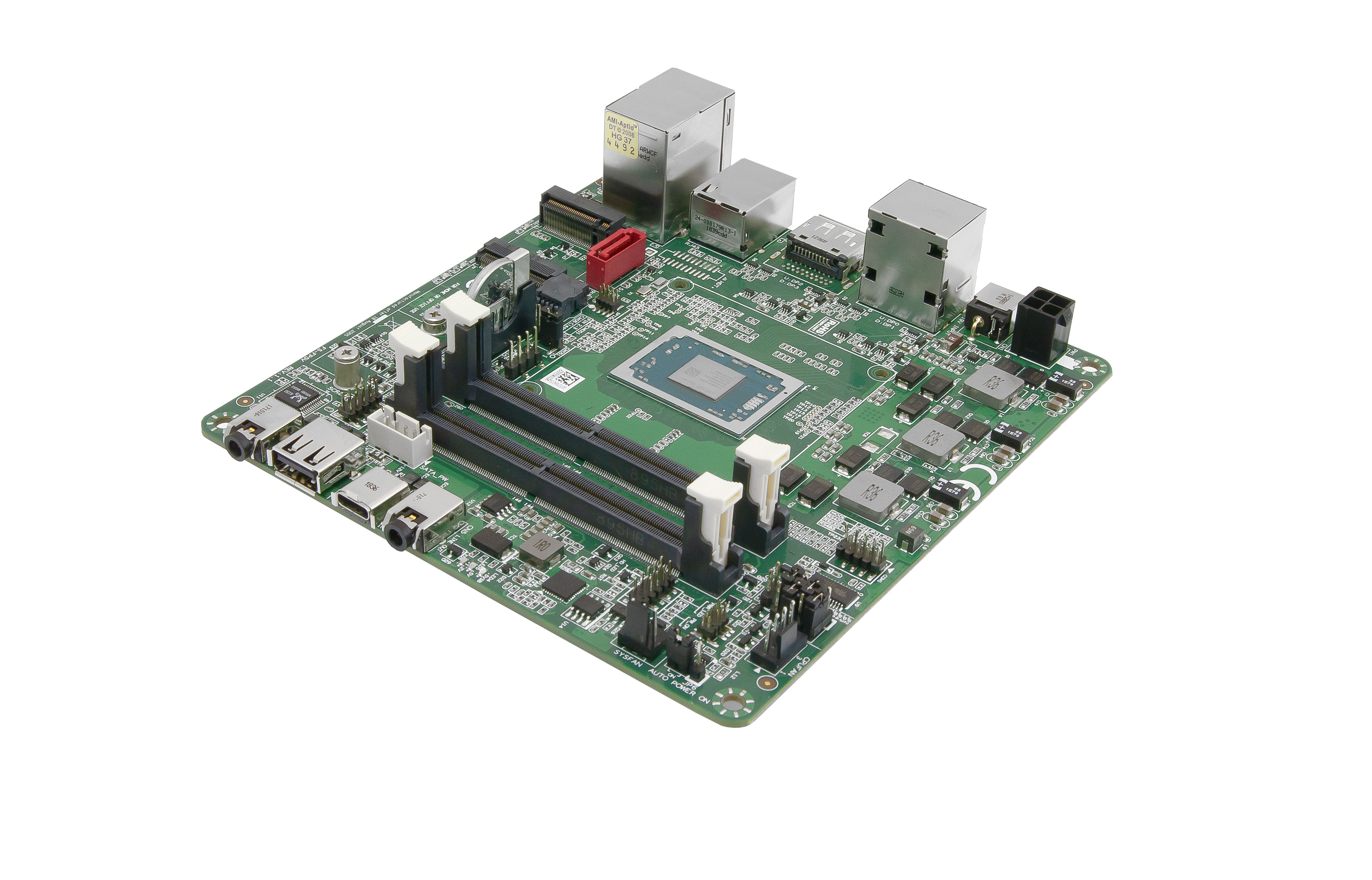
The new SAPPHIRE FS-FP5R 5”x 5” small form factor embedded motherboard is based on the latest AMD Ryzen™ Embedded R-Series Family APUs which features the industry leading Vega GPU graphics combined with the dual-core high-performance “Zen” CPU. Three 4K displays can be supported in addition to dual-channel DDR4-2400 memory, dual Ethernet controllers, and M.2 for WiFi and SSD expansion. The SAPPHIRE FS-FP5R is an ideal solution for small for factor, high resolution visual embedded applications like electronic gaming machines, medical imaging, interactive digital signage, thin clients, POS terminals and more.
Specifications listed for the AMD FS-FP5R 5×5 include:
Processor — AMD Ryzen Embedded R1000 (2x cores, 4x thread Zen cores plus 3x core Radeon Vega 3 graphics); choice of 2.4GHz/3.3GHz R1505G and 2.6GHz/3.5GHz R1606G; Fintek F81803 I/O chipset
Memory — Up to 32GB dual-channel up to DDR4-2400, including ECC
Storage:
SATA III port
M.2 M-Key 2280 with SATA III or PCIe x4
Networking — 2x GbE ports (Realtek RTL8111G)
Media I/O:
3x DisplayPort++ ports
Audio line-out, mic-in (ALC262 HD 4-ch. Audio)
Other I/O:
USB 3.1 Type-C port
3x USB 2.0 ports
RS232/422/485 header
GPIO, front panel I/O, SMBus
Expansion — M.2 E-Key 2230 slot (PCIe x 1) plus M.2 M-Key (see storage)
Other features — Watchdog; HW monitoring; TPM 2.0; intrusion alert
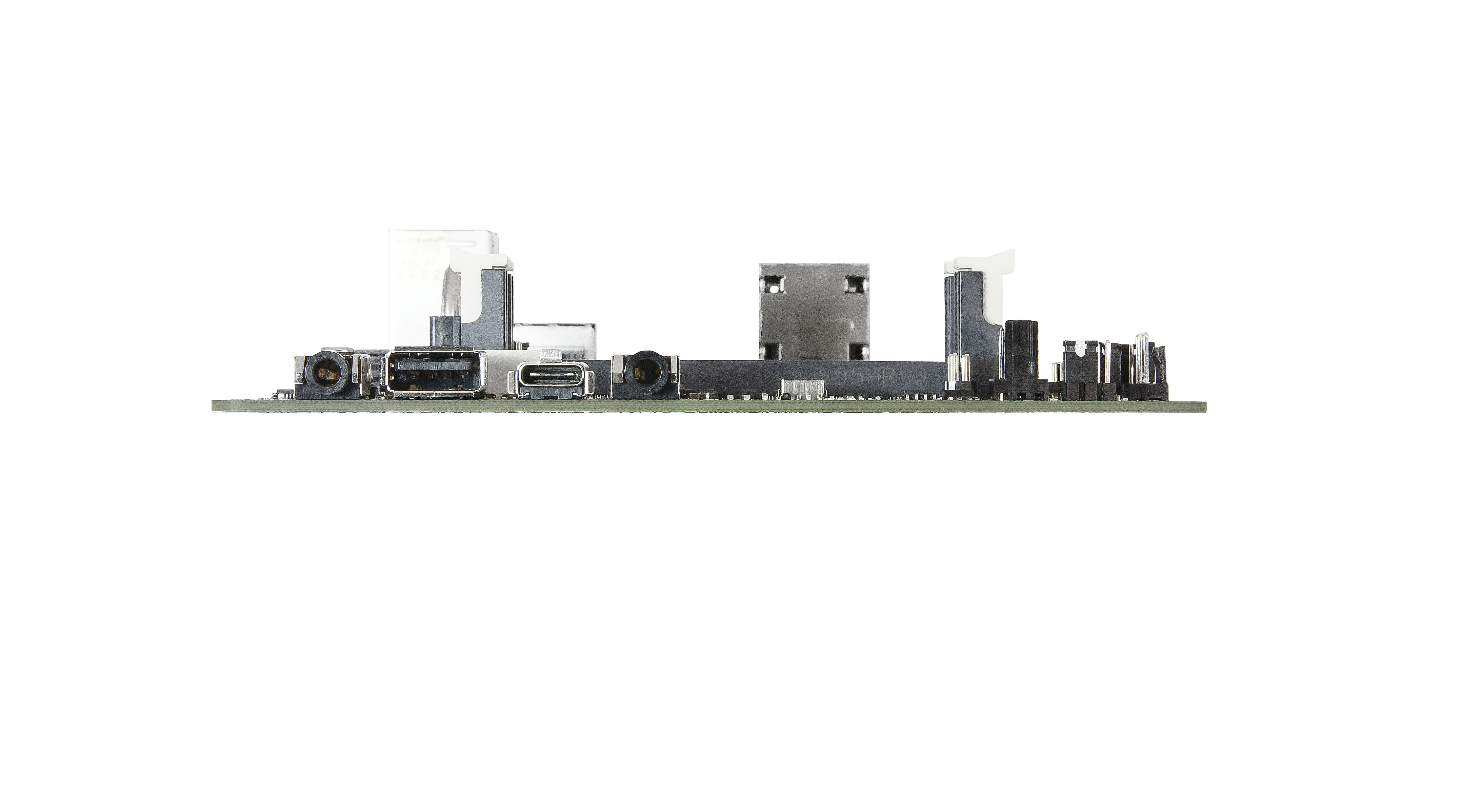
Power — 12-19V DC jack and header
Operating temperature — 0 to 50°C
Dimensions — 147.3 x 139.8mm
The AMD FS-FP5R 5×5 is available for purchase at an undisclosed price. You can submit a form via the Buy Now button to ask for a quote. More information may be found at Sapphire’s AMD FS-FP5R 5×5 product page.
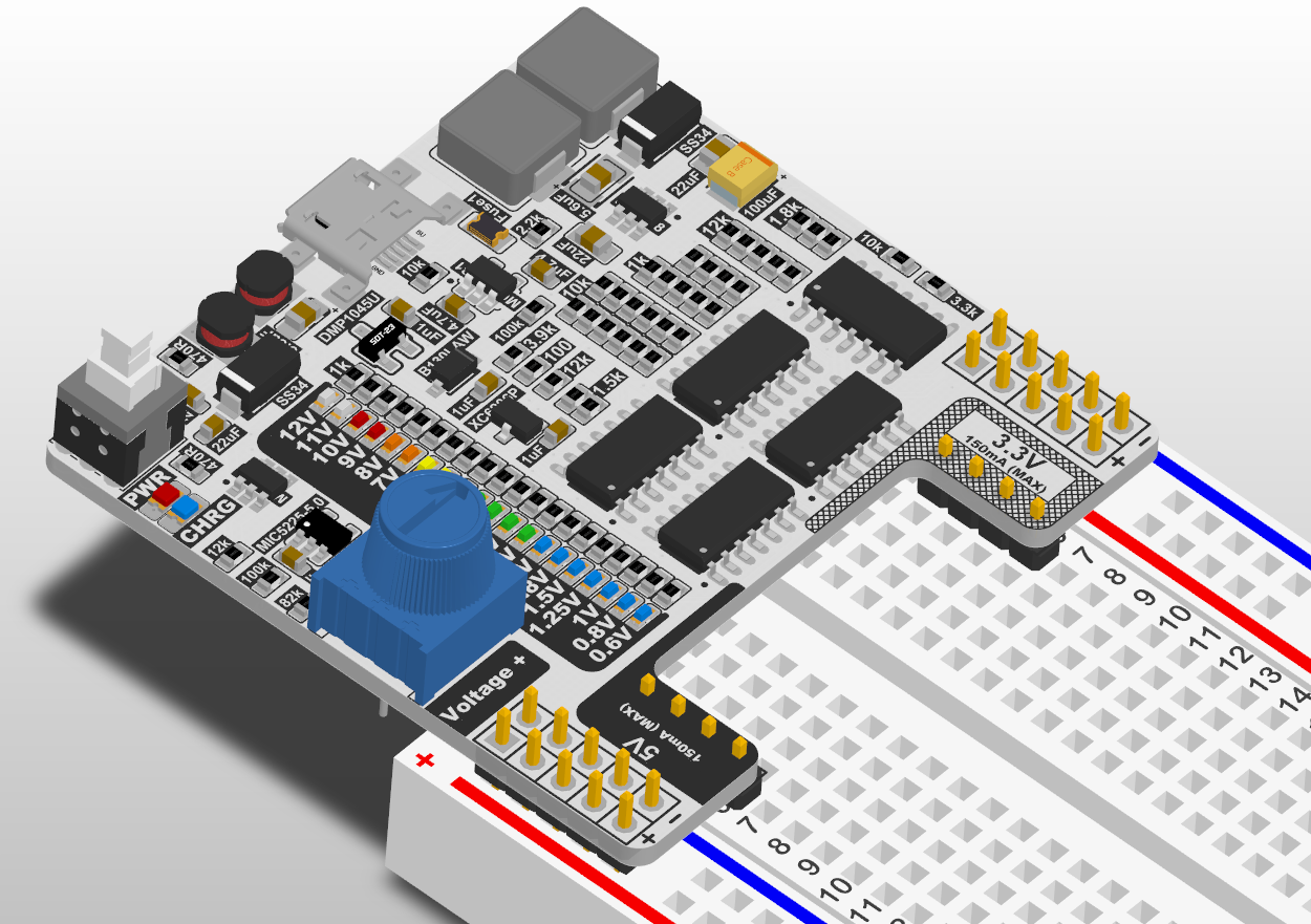
John Loeffler didn’t have much to build a power supply for his bench so he decided to build his own and he did it nicely.
This Project is to produce 3 final Prototypes. All Power Supplies will have USB Charging of Lithium Batteries and a Load Sharing.
Prototype 1: Simple Constant voltage Power Supply Variable from 0.6V to 12V. Will Include 5V and 3V Rails. Voltage indicator will be achieve using Comparators and LED Array
OPEN Power: A Simple Constant Power Supply with Variable Voltage – [Link]