Industry-Leading Energy Harvesting Technology from e-peas Enables Accurate & Continuous Animal Tracking

Highlighting the huge application potential of the company’s advanced power management ICs (PMICs), e-peas has confirmed that its AEM10941 devices for photovoltaic energy harvesting are being incorporated into tracking equipment employed in Australian cattle ranches.

e-peas engineers worked in conjunction with the team at Dutch systems integrator SODAQ on the development and implementation of energy efficient livestock monitoring hardware for Brisbane-based client mOOvement.

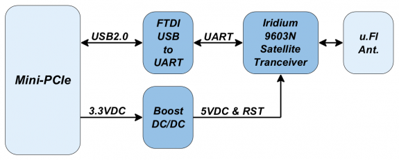
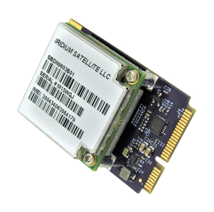
Through use of mOOvement’s smart tracker, valuable data on cattle herds can be acquired concerning their position and grazing patterns, with the ability to set alarms if individual animals are not moving or fenced boundaries have been breached. Attached to one of the cattle’s ears, each tracker comprises an accelerometer, a LoRa communication module (with built-in microcontroller) and a GPS transceiver, as well as a passive NFC tag.

AEM10941 Typical Application

When the design project was embarked upon, it was clearly paramount that the size and weight of the unit had to be kept as low as possible, in order to minimize the impact on the animal. This placed severe restrictions on the surface of the solar panel that could be accommodated (with it measuring slightly less than 19mm x 43mm in total and capable of generating 0.089W). Consequently, the power system needed to be ultra-efficient. In addition, as these trackers will remain on the cattle for a period of 5 years, robustness and long-term reliability were also essential attributes.

e-peas AEM10941

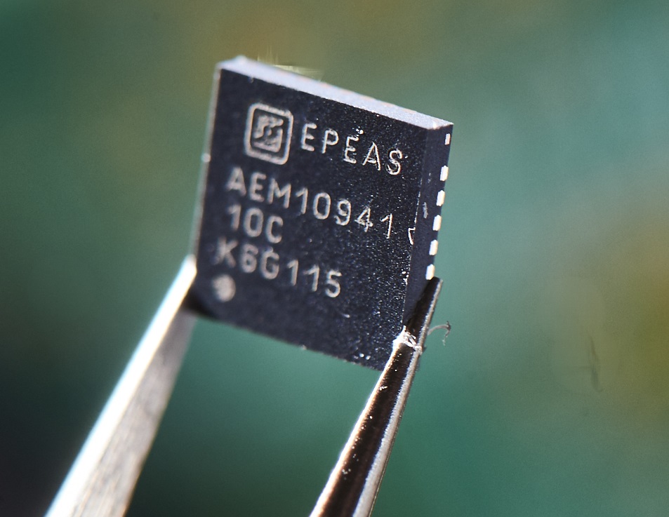
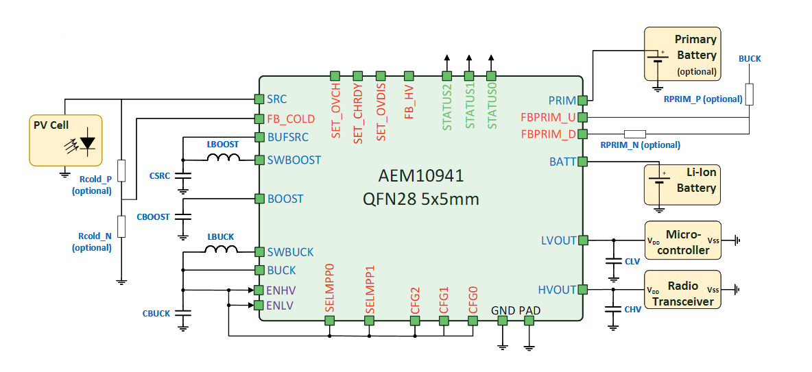
SODAQ’s initial development work on this project started nearly two years back, with e-peas being engaged about 12 months ago. With very little power to draw upon, making full use of what was available was vital. The high energy conversion rate as well as the small footprint of the dual LDO regulated-output AEM10941 met this key criterion, as well as supporting a prolonged operational lifespan even in the uncompromising application environment of the Australian Outback, where exposure to extreme temperature conditions needed to be expected. Thousands of tracking units have already been deployed, with plans to scale further up in near future.

“For this project, there were numerous technical challenges that had to be addressed,” states Ollie Smeenk, Head of Sales & Marketing at SODAQ. “The evident power efficiency of the e-peas PMICs, alongside the strong lines of communication their staff built with us and the exceptional technical support they provided, all proved to be contributing factors that helped us to succeed.”

“In the past, the cattle trackers available to farmers needed to be periodically recharged. This was obviously inconvenient, requiring considerable investment of time and human resources. By being able to efficiently utilize the energy from sunlight such issues can be completely avoided,” adds Pieter Vogels, Chief Commercial Officer at mOOvement. “Together, SODAQ and e-peas, through their respective expertise in IoT and energy harvesting, have supplied us with a system that is not only reliable and operationally effective, but also compact and light enough to be animal friendly.”

For more information on the AEM10941 device, please visit: https://e-peas.com/wp-content/uploads/2017/07/PB_AEM10941_REV0.1.pdf

GW16130 Mini-PCIe Satellite Modem for IoT Applications

The GW16130 is a Mini-PCIe Satellite Modem Radio adapter that provides cost-effective, short burst satellite connectivity for asset tracking, fleet management, telemetry, oceanographic data, grid monitoring and Internet of Things (IoT) applications. The GW16130 features an Iridium 9603N satellite transceiver which allows two-way communications anywhere in the world with a clear line of sight to the sky. The Iridium network consists of 66 satellites and provides 24/7 world wide coverage. The 9603N module is used for short burst data packets (340bytes uplink, 270bytes downlink) and perfect for IoT remote sensor applications with minimal non-realtime data requirements. The GW16130 adapter will work in a full size Mini-PCIe socket that includes a USB 2.0 interface. See the Gateworks website for suggested single board computers that can be used with this adapter. Serial communications to the module is through an onboard FTDI USB to UART bridge. All power conditioning circuitry is contained on the board in addition to an u.Fl antenna connector for connecting an external satellite antenna. Note that an Iridium approved satellite antenna must be used when operating on the Iridium network. The GW16130 adapter requires a monthly data plan which can be established with a number of 3rd party providers. Typical data charges are ~$20 USD per month with 12Kbytes of data included. See the Gateworks Support Wiki for more information on recommended antennas and data plans.

GW16130 block diagram

Features

  • Iridium 9603N SBD Satellite Transceiver
  • Small lightweight module for embedded applications
  • Offers low cost, low bandwidth satellite communications
  • Max Message payload: 340 bytes upload, 270 bytes download
  • Automatic message notification on incomming messages
  • Operates anywhere on earth including North & South Poles
  • Supports E-mail messages or HTTP POST
  • Simple UART AT command interface
  • Operating frequency: 1616MHz to 1626.5MHz
  • 1.6W Average transmit power
  • -117dBm Receiver sensitivity
  • Full industrial temperature operation
  • No SIM card required
  • Onboard u.Fl antenna port for antenna connection
  • Full size Mini-PCIe mechanical form factor
  • Utilizes Mini-PCIe USB 2.0 channel for communications
  • See Gateworks website for compatible SBCs
  • 3.3V Operating Voltage from Mini-PCIe Connector
  • 7.2W@25 C Peak Operating Power (Transmit)
  • 0.85W@25 C Average Operating Power (Receive/Idle)
  • -40C to +85C Operating Temperature
  • 1 Year Warranty

The satellite modem mini PCIe card appears to be available now, but price has not been made public. You can request pricing and/or find more information on the product page.

Homebrew DMX-controlled RGB LED light

Glen has written an article detailing his homebrew DMX-controlled RGB LED light:

This project is a small DMX-512 controlled, color-changing RGB LED light. The light can be controlled via the DMX512 protocol or it can run a number of built-in programs depending on how the software is configured. The light incorporates an advanced 16-bit PIC24 microcontroller with PWM capabilities, a 3D printed enclosure, a laser cut acrylic lid, a custom switching power supply, and a MEMS oscillator. The light measures roughly 2.25″ square by 1.25″ high. This light is the evolution of my RGB LED light designs that span back over a decade.

Homebrew DMX-controlled RGB LED light – [Link]

Robo HAT MM1 – An open source robotics and automation controller for Raspberry Pi

The Robotics Masters Robo HAT MM1 is an open source robotics controller board for Raspberry Pi. It removes the initial barriers to starting any robotics project by providing all the hardware you need in one easy form factor. The wide compatibility with many open source software libraries such as CircuitPython, SeeSaw, and Arduino IDE gives you many options for getting your project to work. The hardware schematics and software will be fully available and open source without limitations.

Features & Specification

  • Raspberry Pi Compatibility (all models with 40-pin header):
    • Model B+, 2B, 2B+, 3B, and 3B+
    • Model A+ and 3A+
    • Zero and Zero W
  • Dimensions:
    • Standard HAT Format (width x depth): 65 mm x 56.5 mm
    • height: TBC
  • Sensors:
    • Accelerometer, Gyroscope, Magnetometer in IMU (MPU-9250)
    • Current Sensor (INA219)
    • Additional space for more sensors in the future (pressure sensor, duel IMU)
  • Processor:
    • 48 MHz SAM D21G
    • 256 KB Internal Flash
    • 8 MiB SPI External Flash Storage
  • Connectivity:
    • 24 programmable Input/Output:
      • 9 x General I/O
      • 8 x 16-bit Servo Output (programmable up to 24-bit)
      • 6 x direct to Raspberry Pi (SW programming, Control, Serial Console)
      • 4 x 16-bit RC Controller Input
      • NEOPIXEL Output
    • JST DroneCode Compliant Connectors:
      • GPS
      • UART
      • SPI
      • I2C
    • USB to serial pass-through to communicate with Raspberry Pi ‘in the field’
  • Power:
    • on-board 5V Regulator (for Raspberry Pi, Servos)
    • on-board small LiPo Battery Charger (for Raspberry Pi)
    • battery pass-through (for Servo, ESC, Raspberry Pi)
    • independent servo power rail (for back-powering from ESC)

Software Compatibility

We wanted a wide range of software libraries to work on the Robo HAT MM1 to enable anyone to build the project that they want. This has the added benefit that the Robo HAT MM1 is able to work in a wide range of use-cases.

Supported

  • CircuitPython (running on the device)
  • SeeSaw (with CircuitPython on Raspberry Pi)
  • Arduino IDE

In Research / Development

We beleive that these libraries can be added on in the future for expanding the number of projects that you can do. We plan on starting work on these libraries in the near future.

  • Scratch Environment (in development)
  • PX4 (DroneCode) Flight Control (researching)
  • ArduPilot Control (researching)

Use Cases

  • Autonomous vehiclesDonkey Car, DIY Robocar, ArduPilot and more.
  • Educators – easy to use for school aged students (testing underway).
  • Makers and Hackers – anyone looking to have fun or create something new with robotics.

The project is going to launch soon on crowdsupply.com and more information is available right now on the same link.

Samsung Galaxy Fold Teardown from ifixit.com

“Taylor Dixon” did a teardown of Samsung Galaxy Fold and reveals what’s inside for the rest of us.

Well, we’ve finally got the Samsung Galaxy Fold on our teardown table. This is, without question, an ambitious first-generation device—the idea of having both a smartphone and a tablet in your pocket at all times is pretty exciting! That said, a number of early reviewers had some durability issues with their review units, ultimately leading to a launch postponement. Are these temporary setbacks? Or are we headed for a full-blown AirPower-style product cancellation? We have no idea—we’re just here for a teardown.

Samsung Galaxy Fold Teardown from ifixit.com – [Link] [update: 26/04/2019] iFixit removes its Galaxy Fold teardown at Samsung’s request

Orange Pi PC 2 – Quad Core 64bit Linux and Android mini PC [Getting Start Guide]

A few time has passed since the addition of Orange Pi PC 2 to the Orange Pi family of SBCs made by Shenzhen Xunlong Software CO., Limited and this successful and high capable board still sales like crazy at $36.65 from various distributors online.

Even though this 85×55mm board isn’t as cheap as the $4 VoCore2 Lite, its $36.65 price tag is justified by the hardware it packs inside. And, it also has almost same price as the $35 Raspberry Pi 3. Orange Pi PC 2 is a single-board quad-core 64-bit computer capable of running Android 4.4, Ubuntu, Debian, Banana Pi, and Raspberry Pi images. But let’s take a closer look at it’s features and specifications.

The board is equipped with 1GB DDR3 SDRAM memory, H5 High Performance Quad-core 64-bit Cortex-A53 processor and a standalone graphics chip (Mali 450). It supports camera input as well as HDMI output and it even has a physical power switch and IR receiver. It takes power using a separate power connector despite the fact that it has a micro-USB port. The absence of WiFi and Bluetooth is a slight turn-down but USB 2.0 ports can be used to add these features. The board also includes a Gigabit Ethernet port and three USB 2.0 ports.

Hardware specifications

  • CPU: Allwinner H5 64-bit Quadcore (Cortex-A53)
  • RAM: 1GB DDR3
  • GPU: Mali-450
  • Storage: 2MB NOR Flash, up to 64GB via MicroSD card
  • Connectivity: 2xUSB 2.0, 1xUSB 2.0 OTG, HDMI, 10/1000 RJ45, IR receiver, camera interface, 40-pin header
  • Audio: 3.5mm jack, inbuilt mic
  • Operating System: Ubuntu Debian, Raspbian, Android

Getting Started with Orange Pi PC 2

  • You need to get these accessories to start using your Orange Pi: TF card (minimum 8 GB), HDMI to HDMI lead or HDMI to DVI lead (for monitors with DVI input), AV video lead, DC power adapter, keyboard and mouse, plus Ethernet cable/USB WiFi and Audio lead as an option.
  • Prepare your TF card
    1. Insert your TF card into your computer. The size of TF should be larger than the OS image size, generally 8GB or greater.
    2. Format the TF card. (using this tool for Windows, and some commands for Linux)
      1. Run fdisk –l  /dev/sdx command to check the TF card node.
      2. Run umount /dev/sdxx to unmount all the partitions of the TF card.
      3. Run sudo fdisk /dev/sdx command to configure TF card. Use o command to delete all partition of TF card and use n command to add one new partition. Use w command to save change.
      4. Run sudo mkfs.vfat /dev/sdx1 command to format the new created partition of TF card as FAT32.
        (x should be replaced according to your TF card node)
      5. Download the OS image from the Downloads webpage.
      6. Unzip the download file to get the OS image
      7. Write the image file to the TF card using this software on Windows and this command on Linux: sudo dd bs=4M if=[path]/[imagename] of=/dev/sdx (x should be replaced according to your TF card node)
  • Set up your Orange Pi PC following the steps in the diagram

  • Shut down your board: You can use the GUI to shut down the Orange Pi PC2 safely or just run this command in the terminal:  sudo halt or  sudo shutdown –hnow This will shutdown the OrangePI safely, (just use the power key to turn off might damage the TF-cards file system). After that you can press the power key for 5 seconds to turn it off. Full guide and any updates on the OS image will be available here.

This is the main procedure to get started with OrangePi PC 2.

This open source SBC (single board computer) is a great option to start building IoT devices, DIY projects and for development purposes. You can use it as a mini-computer, a wireless server, music and video player,etc. You should remember that sky is the limit when it comes to open source boards.

The Orange Pi PC 2 is up for sale on www.banggood.com and you can get it now for $36.65.

AJIT – First-Ever “Made in India” Microprocessor Designed By IIT Bombay

In this modern era, the electronics industry is incomplete without microprocessors. From daily household appliances to space exploration – microprocessors are accompanying us everywhere and making lives way easier. But, independently designing and manufacturing a processor is an extremely complicated task and done by only a few countries like the US, Italy, France, Japan, Taiwan, Singapore, Malaysia, etc. India was not in the list, that’s until recently IIT Bombay, one of India’s premier technology institute developed the country’s first-ever indigenously-built SPARC ISA architecture based microprocessor called AJIT, led by Prof. Madhav Desai.

A plate full of AJIT - India's First-Ever Microprocessor
A plate full of AJIT – India’s First-Ever Microprocessor

Here’s a quick introduction of microprocessor: A microprocessor is an IC comprises of millions or more transistors and function as the controlling unit of a micro-computer, fabricated on a small chip capable of performing ALU (Arithmetic Logical Unit) operations and communicating with the other devices connected to it. Microprocessor consists of an ALU, register array, and a control unit.

This project by IIT Bombay comes under the Government of India’s “Make In India” initiative which encourages both multinational and domestic companies to design and manufacture products within the country to make India a global manufacturing hub. The name “AJIT” is not an acronym and is derived from Sanskrit, meaning “Someone who has not been conquered“. As far as I could gather information, the AJIT microprocessor uses SPARC ISA architecture. SPARC (Scalable Processor Architecture) is a reduced instruction set computing (RISC) instruction set architecture (ISA) originally developed by Sun Microsystems.

This 32-bit microprocessor is clocked at around 70-120 MHz, features an arithmetic logic unit (ALU), a memory management unit, a floating point unit (FPU) for high-speed floating point operations, and also a hardware debugger unit. As per the researchers associated with development, a clock speed of 400-500MHz is obtainable in the next upgrade. AJIT is a 180nm technology-based chip,  but the researchers plan to move to a 65nm process eventually. They published the tool AHIR-V2 which used in this project on GitHub.

AJIT is pretty cheap, it’ll cost only  ₹100 (100 Indian Rupees) which is equivalent to $1.44. Unlike Shakti, which is India’s first-ever RISC-V architecture based microprocessor developed in collaboration with Bluespec, a US-based semiconductor tool design company, AJIT is truly indigenous. This microprocessor is not for smartphones or PCs, rather it is primarily designed to power India’s satellites for Indian Regional Navigation Satellite System (IRNSS) Program. One of the researchers of the project team stated,

We are planning to use AJIT in the receivers being developed for NAVIC or IRNSS, an indigenous navigation system for the Indian subcontinent

Though, some of the other applications include set-top boxes, control panels for automation systems, traffic light controllers or robotic systems.

To learn more on AJIT and the journey of India’s semiconductor industry, check this article at Research MattersAlso, you may check this and this Reddit posts.

Sensirion SVM30 Multi-Pixel Gas Sensor Module

Sensirion SVM30 Multi-Gas, Humidity, and Temperature Sensor Combo Module is ideal for measuring indoor air quality in devices such as air purifiers, air conditioners, and other air treatment products. The SVM30 combo module contains an SGP30 gas sensor as well as an SHTC1 humidity and temperature sensor. The SGP30 multi-pixel gas sensor combines multiple metal-oxide sensing elements on one chip. This means a total VOC signal (tVOC) and a CO2 equivalent signal (CO2eq) can be measured through that one sensor chip. Sensirion SVM30 provides a solution to design challenges like thermal decoupling of the sensors and compensation of humidity cross-sensitivity.

Block Diagram

SVM30 Block Diagram

The gas and RH/T sensor components on the SVM30 are designed with Sensirion’s CMOSens® Technology. This technology offers a complete sensor system on a single chip, including the sensing elements, analog and digital signal processing, analog-to-digital converter (ADC), calibration and data memory, and a digital communication interface supporting I2C standard mode. The sensing element also offers robustness against contamination by siloxanes present in real-world applications, enabling long-term stability and low drift.

Features

  • Measures indoor air quality parameters tVOC, CO2eq, relative humidity, and temperature
  • Fully factory calibrated and tested
  • Digital I2C interface
  • Automatic baseline compensation and humidity compensation of MOX gas sensor
  • Long-term stability and reliability

Specifications

  • 4.5V to 5.5V supply voltage
  • 49mA Avg. current
  • Package: 39mm x 15mm x 6.5mm PCB
  • 1s sampling rate
  • -20°C to +85°C operating temperature range
  • ±1°C Typ. temperature accuracy
  • 0% to 100% RH humidity measurement range
  • ±5% RH humidity accuracy
  • Output range: TVOC – 0 to 60,000ppb; CO2eq – 0 to 60,000ppm
To learn more, visit www.mouser.com/sensirion-svm30

Compulab Airtop3 is bringing performance to the edge

Compulab is introducing Airtop3 – a ruggedized small-form-factor fanless IoT edge server powered by an 8-core Intel® Core™ i9-9900K Processor and Nvidia Quadro RTX 4000, both passively cooled using Compulab’s Natural Airflow technology. With a footprint of just 7.5 liters, Airtop3 can passively dissipate up to 300W and operate at a wide temperature range of -40°C to 70°C. Airtop3 ships with a 5 year warranty.

Fanless Core i9 9900K and Quadro RTX 4000

IoT edge server can reduce processing latency, network bandwidth requirements and TCO, provided that it is sufficiently powerful, robust and easy to deploy.

Airtop3 presents a unique value proposition for edge computing in harsh environments:

  • Exceptionally high performance – 8-core, up to 5 GHz Intel Core™ i9-9900K or Intel Xeon coupled with Nvidia Quadro RTX or GeForce GTX GPU and high RAM capacity up to 128 GB
  • Rich storage, networking and I/O, each can be enhanced thanks to Airtop3’s modular design
  • Passive cooling across wide temperature range and a rugged all-aluminium small-form-factor housing
  • Maintenance-free design, tool-free serviceability and advanced monitoring and diagnostics provisions

“Apparently, the appetite for performance at the IoT edge knows no boundaries”

said Irad Stavi, Chief product officer at Compulab.

“We are seeing remarkable performance gains in the latest generation of CPUs and GPUs, but with great power comes greater power consumption. However, our engineers were able to improve the thermal headroom of Airtop3’s Natural Airflow cooling by over 30% so there was no need to settle for low power chips. This makes Airtop3 a small-form-factor fanless IoT edge server with unprecedented performance.”

“Benchmarks indicate that Airtop3 is nearly twice as powerful as Airtop2”

said Yuval Sela, Airtop hardware architect.

“To achieve that, power delivery in Airtop3 is completely revamped and can now support the most powerful Intel 9th generation Core CPUs and even 160W NVIDIA RTX GPU.”

Airtop3 performance and features

Airtop3 supports 9th Generation Intel® Core™ i9 Processors and future Intel® Xeon® E Processors, including the highest power 95W Core i9-9900K. The maximum RAM capacity is 128 GB DDR4-2666. Standard storage is comprised of 6 devices – two NVMe SSDs – up to 2 TB each and four 2.5” SATA 3 HDD/SSD with RAID support. Standard networking includes two GbE ports and support for Wi-Fi 802.11ac and 4G modem. Standard I/O includes 3 4K displays, 6 USB 3.1 ports, 3 RS232 and audio. This feature set may be satisfactory in some cases, but IoT has many specialized applications – deep learning may require a discrete GPU, automotive applications often require high capacity of high-speed storage, machine vision usually utilizes integrated PoE ports. For these use cases and other, Airtop3 offers functional enhancements.

Enhanced graphics

Airtop3 has a PCIe x16 (PEG) slot with Natural Airflow passive cooling that supports up to 160W Quadro RTX 4000 graphics card. This powerful CPU + GPU setup is effective for low latency edge analytics workloads involving image recognition, machine learning or inferencing.

The four displays of the graphics card can work in tandem with the integrated graphics for a total of seven 4K displays.

Enhanced storage

The standard two NVMe cards and four 2.5” SATA SSD/HDD support up to 20 GB with RST or software RAID and are passively cooled in a dedicated thermal zone.

Storage can be enhanced using Airtop3’s NVM3 card installed in the PEG slot. NVM3 supports additional three NVMe cards up to NF1 30110 form factor.

NVM3 enables remarkable data rate of over 9500 MBps and increases max storage capacity to over 60 TB. It allows installing SSDs with power loss protection (PLP).

Enhanced networking

Dual Gbit Ethernet (Intel i210 + Intel i219) and optional WiFi 802.11ac + 4G/LTE modem are available as a standard. For higher bandwidth, dual 10 GbE card can be installed in the PEG slot. Extra networking capabilities can be added using a FACE Module

  • FM-LAN adds 4 independent GbE ports – useful for routing applications
  • FM-PoE adds 4 GbE ports, each with 802.3af PoE source which simplifies setups involving IP cameras
  • FM-OPLN adds 2 GbE SFP+ optical LAN ports which enables longer range, better immunity and higher security
Airtop3 Block Diagram

Cooling, durability, modularity and monitoring

Airtop3 cooling is based on Compulab’s Natural Airflow technology that stimulates airflow without moving parts – by the waste heat of the 3 major heat sources (CPU, GPU and storage devices) each having a dedicated thermal zone.

The 7.5 liter housing is all-aluminium made of die-cast and extruded parts with precision machining for seamless fit, shock and vibration resistance.

Airtop3 supports Compulab FACE Modules (Function And Connectivity Extension Modules) which enable various application specific networking and I/O capabilities. A new FACE Module designed specifically for Airtop3 – FM-AT3 adds 2x USB 3.1 gen 2 (one USB type-C) + 1x USB 3.1 gen 1, front audio jacks, mini-PCIe socket with SIM card, micro-SD and diagnostics LEDs for troubleshooting RAM, BIOS and display issues.

It is very easy to install RAM and storage devices in Airtop3 thanks to the clamshell tool-free opening.

Airtop3 includes the I3M OLED display – for displaying vital runtime information including clock rate, temperature and power consumption.

Price and availability

The Airtop3 is available starting at $999 for the barebone (no RAM) Celeron model and $1,639 for the Core i9-9900K model with 8GB RAM. Build-to-order versions require six weeks lead time. More information may be found in Compulab’s Airtop3 announcement, as well as on the product page and shopping page.

To order Airtop3 online please visit www.fit-iot.com/web/product/airtop3-build-to-order

Compulab is offering a risk-free evaluation program for business customers. For details please visit www.fit-iot.com/web/products/airtop3/airtop3-b2b

For more information

www.fit-iot.com/web/products/airtop3

BIT4 is a 4Bit microcontroller – fully programmable with only three buttons.

BIT4 is a 4Bit microcontroller – fully programmable with only three buttons.

The BIT4 microcontroller has 256 Bytes of programm memory, split in 16 pages with each 16 instructions. A instruction is 8bit wide and consists of an command and data:

To enter the programming mode, hold BTN2 down, press the RESET button once and then release BTN2. In programming mode, step through the instructions with BTN2. When going to a new instruction, the leds will show the current address for a fraktion of a second. With BTN1 the value of the command and data of the current instruction can be changed. When stepping to a new address with BTN2, the instuction of the address above gets saved in the EEPROM. At the end, press RESET to leave the programming mode and to start the programm execution.

all design files are available on github.com

TOP PCB Companies