It detects stationary and moving people just like a PIR, but it can do that also behind doors and thin walls, by taking advantage of the Doppler effect. By Boris Landoni @ open-electronics.org:
The detection of people, animals and hot bodies in general has been done for years using passive infrared radars, also known as PIR, which work by placing a pyroelectric sensor, so a heat sensor, behind a Fresnel lens, which has the ability to focus on just one point the infrared rays coming from the frontally detected heat, emitted by moving objects within a certain angle.
PIR sensors cover a wide array and variety of applications and represent by now a low-cost solution to protect ourselves from home invasion, automatically activate utilizers when moving people are detected etc., although they have the limitation to be able to detect only whatever can be seen: they cannot detect, even at a short distance, people moving behind doors and windows, so if we employ them in a home security system, they will only be activated when the intruder is already inside the room where the sensors are installed.
In order to have a preemptive protection, we can make use of radiofrequency sensors and, to be precise, microwave sensors, because they can detect people behind doors and even walls as long as they are not too thick or made of reinforced concrete or metal, or walls containing metal plaster reinforcement grids (for bladder walls) or cavity for sliding doors such as Scrigno.
Microwave Presence detector works using Doppler Effect – [Link]
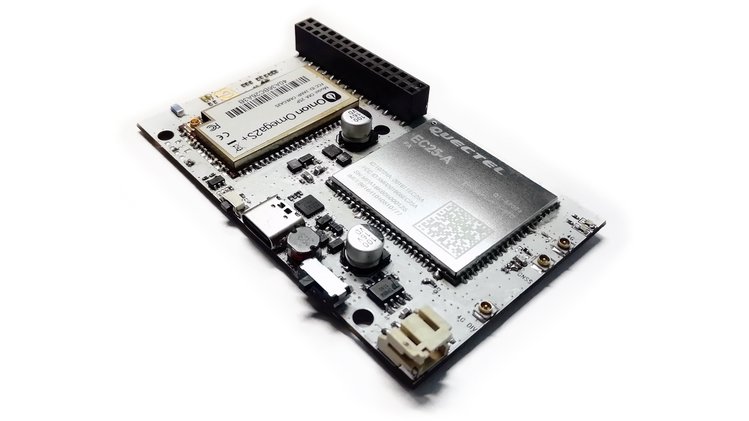
The Omega2 LTE is a Linux IoT computer with Wi-Fi and LTE cellular connectivity.
Effortlessly deploy your existing IoT applications in remote areas and no longer be limited by the range of Wi-Fi networks. The Linux network stack makes the switch between WiFi and cellular data seamless to user applications.
Take your existing NodeJS or Python IoT project outside the building with ZERO effort!
The Omega2 LTE has all the hardware you need for:
Remote sensor applications – as a hub or end-node
Real-time asset tracking
LTE Hotspot – share the high-speed LTE data connection with IoT devices, laptops, and tablets
Now with GNSS Support
On top of that, the Omega2 LTE also has GNSS global positioning capabilities, further extending the possible use cases to include real-time asset and fleet tracking.
Compatible with GPS, GLONASS, Galileo, Beidou, and other regional systems
Easily report geopositioning and other data to remote servers using the LTE data connection
Self-contained and Battery Powered
Omega2 LTE is a self-contained device that is smaller than a standard breadboard, making it a great form-factor for use in any IoT project. Just add LTE antennas and power.
It’s flexible when it comes to power: you can provide power from any USB port or with a LiPo battery. Connected batteries will automatically recharge when USB power is present, and will act as a back-up power supply if USB power is not stable.
The Omega2 LTE features a MediaTek MT7688 MIPS WiSoC, 128Mb DDR2 RAM, and 32Mb of Flash.
Wireless Networking Capabilities
The Omega2 LTE specializes in wireless networking, sporting 4G LTE connectivity and Wi-Fi capabilities, making it ideal for outdoor and remote sensor hub applications.
The Wi-Fi interface can simultaneously host its own Wi-Fi access point and connect to existing Wi-Fi networks
It enables uses cases that are not limited by the range of Wi-Fi networks since the 4G LTE data connection provides internet connectivity as long as there is cellular signal
The LTE data connection can also be shared through the Omega’s Wi-Fi access point or even through ethernet using the Ethernet Expansion
The Omega2 family
Omega2 LTE is the latest addition to the Omega2 family and is based on the Omega2S module so it builds on all of the work we’ve done over the past three years since launching the Omega2. That means it’s an all-in-one device that features the standard Omega2 30-pin header, and it comes pre-loaded with the OpenWRT Linux OS. Also, it’s compatible with our existing eco-system of Omega2 Expansions. OnionOS provides an intuitive user interface through the browser with no installation required. Write code, run commands, and use apps to interact with your Omega2 LTE.
“Effortlessly deploy your existing IoT applications in remote areas and no longer be limited by the range of Wi-Fi networks. The Linux network stack makes the switch between WiFi and cellular data seamless to user applications.”
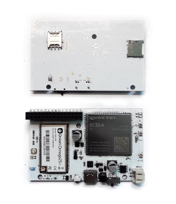
Upgraded USB port for power and serial command line access to USB Type-C
Does not feature 8 GB eMMC – Instead the operating System runs on on internal storage of Omega2S+ module and has a MicroSD slot for extending storage space
Added 4G LTE network status and activity LEDs – Does not have a RGB Notification LED
Rectangular, enclosure friendly board layout instead of the the signature Onion three-corner-cut design.
Still features 30-pin I/O header and support for Omega2 Expansions
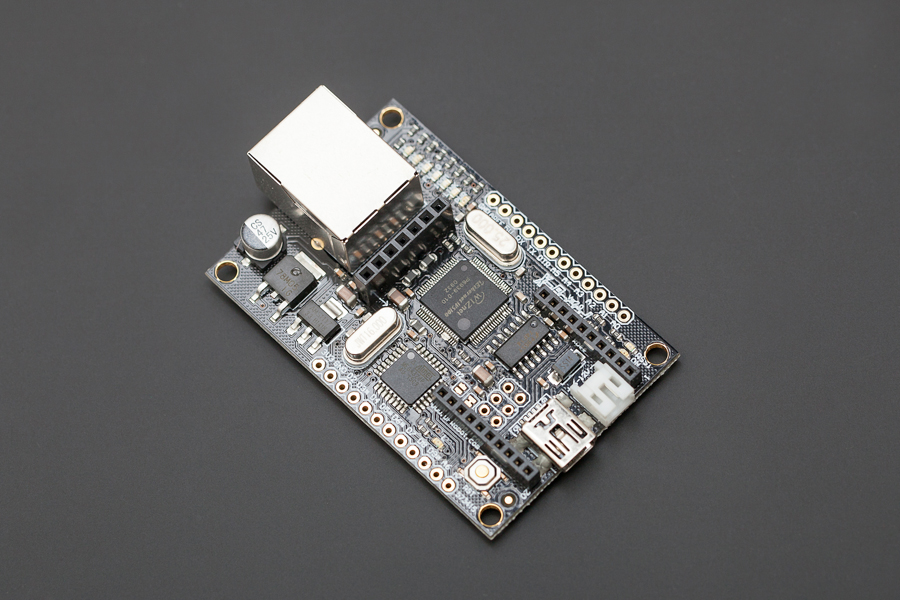
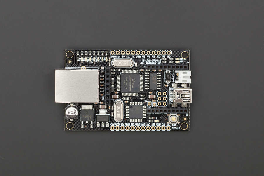
This is Version 2.0 of the Xboard. The main improvement is that it now operates at 5V, making it compatible with most sensors and I2C protocol without the need of a voltage level converter.
The XBoard is a unique Arduino board which features a WIZnet ethernet port, an XBee socket, and an ATMega328. This board will add wireless XBee control as well as internet connectivity to your projects. It’s great for anything from home automation to robot control. The possibilities are endless!
It has 8 Analog I/O pins and 8 digital pins, 4 of which have PWM (indicated by an asterisk). It is compatible with all XBee modules, and also comes with an integrated socket for APC220 RF Module or DF-Bluetooth Module. The XBoard can be programmed via an FTDI programmer or via the ICSP header. Power is provided through a Mini USB connector. You can setup a web server through which you may communicate with a remote Arduino using XBee radios, bluetooth or APC modules.
Specification
MCU:Atmega328P low voltage version (16Mhz)
Ethernet:WIZ5100
Arduino Uno bootloader
Supply voltage:5~12v
Output voltage:5v/3.3v
Digital IO: 8
Analog In: 8
Envionment Friendly: Rohs Compliance
more information can be found on the following documents:
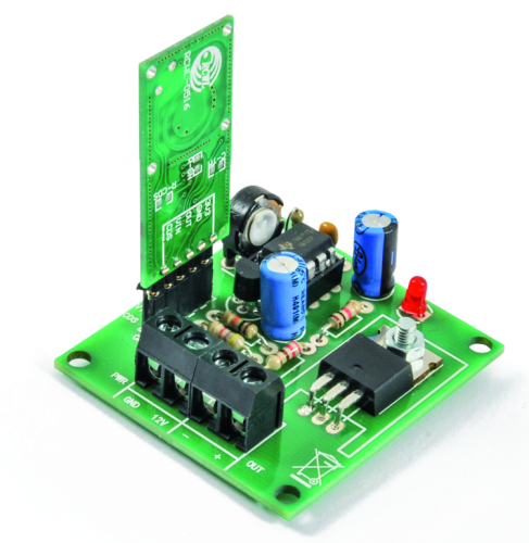
A low-cost, easy-to-build, high-power LED controller with a built-in programmable timer.
This project is published with author’s permission and uploaded through our Upload Project
The main objective of this project is to design a maintenance free and low-cost light which automatically turns on and off at the predetermined time of the day.
This kind of light helps to reduce power waste and save energy. In these days people have a habit to turn on at least one light of there residence if they are going out of home for a couple of days. Then lights start to blazing all day and night and waste lots of energy. If we can use this programmable light, then we can configure it to turn on every night and turn off at the next day by without any human involvement.
The core component of this programmable light is ATmega8 low power CMOS microcontroller. The main reason to select this microcontroller is it’s lower cost and higher availability. Except for the above two reasons this microcontroller also bundled with a rich set of peripherals which including 23 GPIOs, 3 independent timers, Two-wire serial interface, EEPROM, etc.
Apart from ATmega8 microcontroller, this system uses DS1307 real time clock to maintain system time. Like ATmega8, DS1307 is also a very popular RTC in the market.
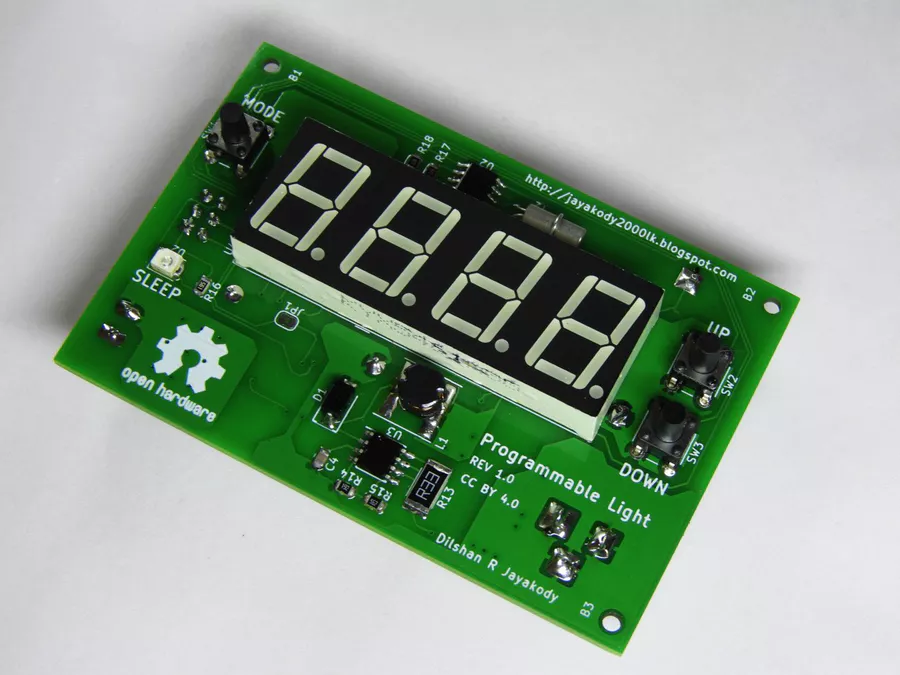
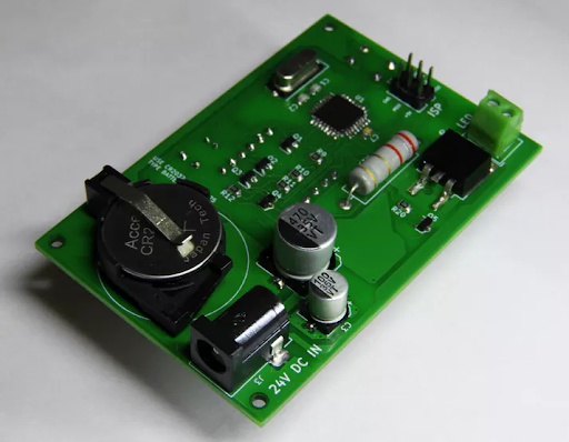
Fig 1: Front side of the programmable light controller
This controller is designed to work with a 24V DC power supply. The main reason to select 24V is that most of the medium power LED modules in the market are designed to work with that voltage. During my search all the medium power LED modules which I found are designed to work with 20V – 28V range. Out of those LED modules, the majority of modules are rated for 24V input.
For this circuit, the recommended power supply is 24V 1.5 A portable switch mode power supply. Except for the LED driver stage the all other parts of this light controller is designed to work with 5V. MC34063 DC-to-DC converter is used to supply 5V to those components.
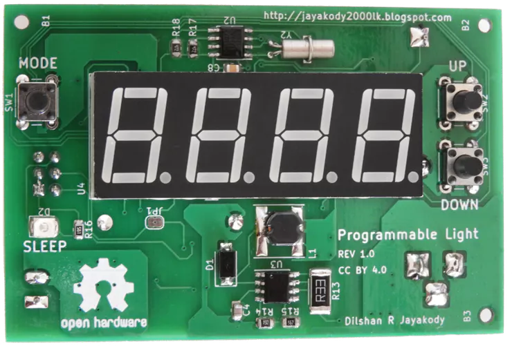
Fig 2: Back side of the programmable light controller
To reduce the size I design this system using surface-mounted components, but this system can also build using through-hole type components. At the prototype stages, I build this system entirely on a breadboard using through-hole type parts.
To build 7W light, I used LED lamp parts available in the market which including Warm white 7W LED panel, aluminum lamp shell (heatsink) and diffusing cap (lamp cover).
Construction
As mentioned previously this programmable light can build in many ways which including using PCB, Veroboard, breadboard, etc. The most favored way to construct this system is using a PCB.
The PCB design which I provide is based on 2 layers and because of that, it’s advised to build this PCB using some PCB fabrication service.
Fig 3: All the components of this board are soldered using conventional soldering iron.
After fabricating PCB, you can start soldering the components into it. At first, try to solder SMD ICs. After soldering all 3 ICs next start with small SMD components such as resistors, capacitors and SOT-23 transistors. I highly suggest installing seven segment display, DC jack base, battery clips and terminals header at the last stages of the soldering.
Upload firmware into the system
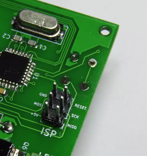
Once all the components are assembled the next task is to feed firmware into the microcontroller. To upload the firmware the most recommended method is to use AVR in-circuit programming (ISP) compliant adapter.
This system is designed to work with standard 6-pin AVR ISP interface and there are plenty of programmers are available for this interface.
During my prototype assembly, I used aUSBasp programmer to flash the microcontroller with firmware.
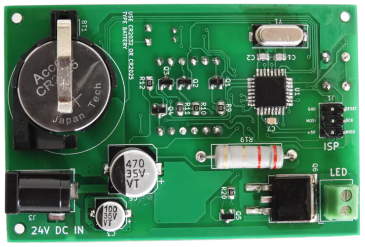
Fig 4: ISP header to connect programmers.
During the firmware upload process pays extra attention to ATMega8 fuse settings. To get intended results low-fuse byte should set to 0xEF and high-fuse byte should set to 0xD9. For more details refer project documentation at the GitHub.
While using ISP make sure to disconnect the 24V power supply from the system.
LED module
After uploading firmware, the only remaining task is to connect the LED module into the controller.
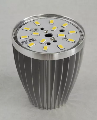
Before soldering 7W LED module, fix it to the provided heatsink. To improve thermal transfer make sure to apply thermal grease between the LED module and heatsink.
Fig 5: Partially assembled LED module.
While LED lighting for long hours its temperature increase up to 70°C – 80°C. Because of this, make sure to take necessary action(s) to isolate the LED wire line with temperature. To overcome this, in prototype build I drive this wire through a high-temperature resistant Basalt sleeve.
Using the light controller
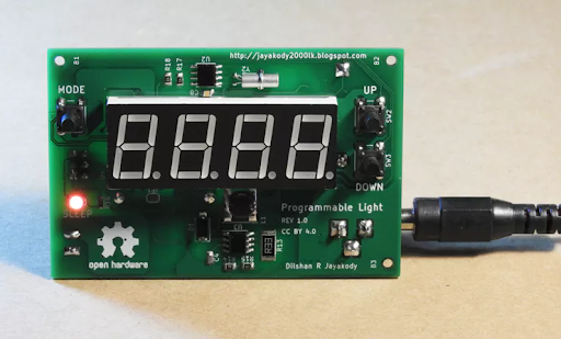
At the first power up light controller starts with default settings. To modify those settings hold down “MODE” button for a few seconds and then it opens the System menu.
System menu consists of 4 options such as “SYS”, “ON”, “OFF” and “—”. You can modify the value associated with each option by pressing the “MODE” button. In System menu press “UP” or “DOWN” buttons to navigate over the available modes.
Fig 6: Light controller in idle state.
In “SYS” mode user can change the system time. Likewise in “ON” and “OFF” modes, the user can set the light on and off times respectively.
To leave the System menu, press the “MODE” button in “—” mode.
The light controller firmware is designed to switch to the idle state if the user is not involved with the system for a long period of time. In the idle state, seven segment display of the light controller is not active. In most occasions SLEEP indicator also got activate in an idle state.
The light controller project which described in this article is a certified open hardware project. All the design files and firmware source files of this project are available to download at GitHub.
The compiled firmware and PCB Gerber files are also available to download at the GitHub release page.
All the content of this project are distributed under the terms of the following license:
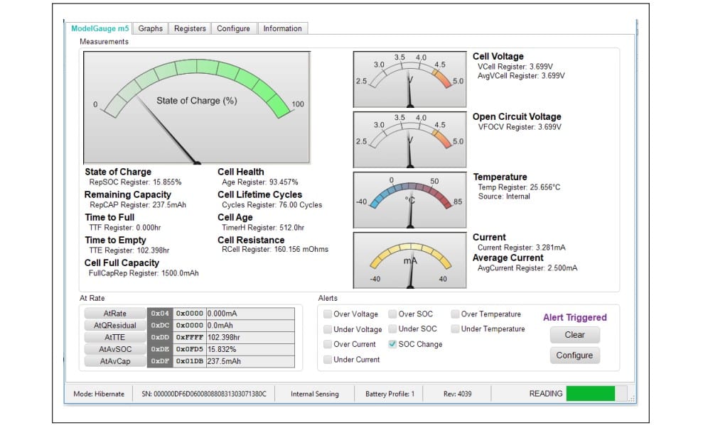
The MAX17262X evaluation kit (EV kit) from Maxim Integrated Products is a fully assembled and tested surface-mount PCB that evaluates the stand-alone ModelGauge™ m5 host-side fuel-gauge IC for lithium-ion (Li+) batteries in handheld and portable equipment.
This EV kit supports a variety of applications such as: Bluetooth Headset Cases, Handheld Computers and Terminals, Health and Fitness Monitors, Home and Building Automation, Sensors, Medical Devices, Toys, Wearables and Smartwatches, and similar devices.
The MAX17262X EV kit includes the Maxim DS91230+ USB interface, IC evaluation board, and RJ-11 connection cable. Windows®-based graphical user interface (GUI) software is available for use with the EV kit and can be downloaded from Maxim’s website. Windows 7 or newer Windows operating system is required to use with the EV kit GUI software.
The ModelGauge m5 EZ makes fuel-gauge implementation easy by eliminating battery characterization requirements and simplifying host software interaction. The ModelGauge m5 EZ robust algorithm provides tolerance against battery diversity for most lithium batteries and applications.
Features and Benefits
ModelGauge m5 Algorithm
Monitors from 1S Cell Packs
Battery Pack Input Voltage Range of +2.3V to +4.9V
Thermistor Measurement Network
Windows 7 or Newer Compatible Software
Proven PCB Layout
Fully Assembled and Tested
The ModelGauge m5 EZ algorithm combines the short-term accuracy and linearity of a coulomb counter with the long-term stability of a voltage-based fuel gauge, along with temperature compensation to provide industry-leading fuel-gauge accuracy. The IC automatically compensates for cell-aging, temperature, and discharge rate, and provides accurate state-of-charge (SOC) in percentage (%) and remaining capacity in milliampere-hours (mAh) over a wide range of operating conditions.
As the battery approaches the critical region near empty, the ModelGauge m5 algorithm invokes a special correction mechanism that eliminates any error. The IC provides accurate estimation of time-to-empty and time-to-full and provides three methods for reporting the age of the battery: reduction in capacity, increase in battery resistance, and cycle odometer.
The EV kit is fully assembled and tested. The EV kit software can be run without hardware attached. It automatically locates the hardware when connections are made. After communication is established, the IC must still be configured correctly for the fuel gauge to be accurate.
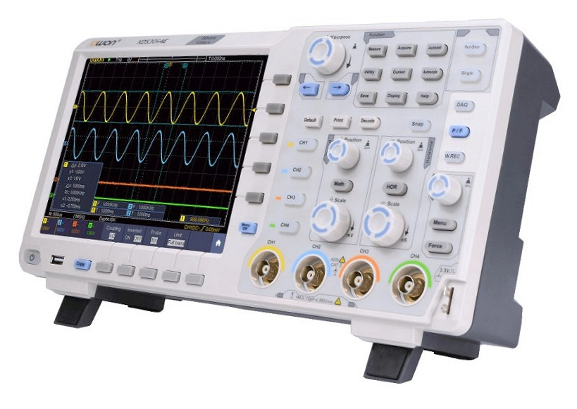
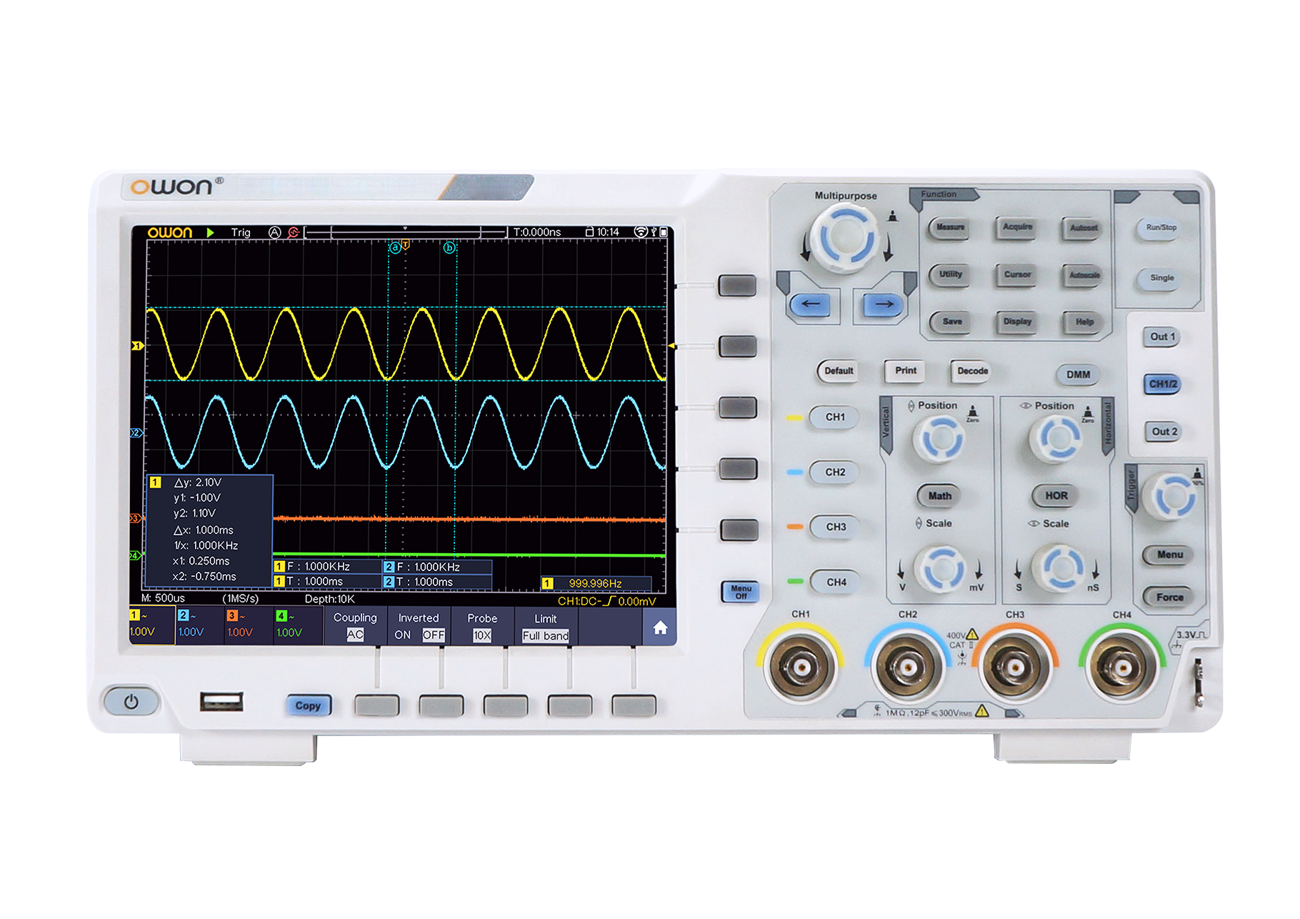
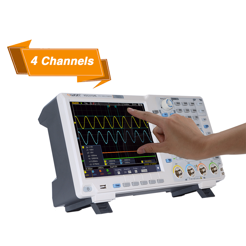
The new OWON XDS3064 4-in-1 digital storage oscilloscope is a reliably measurement tool for a really good price. The colorful 8″ (20.3 cm) TFT LCD panel with the resolution of 800 × 600 allows an excellent readability of the wave, especially in regards to high data volume or many waves covered reciprocally.
The special features of the XDS3000 series are a multitouch surface (from the XDS3102A) and a high vertical resolution up to 14 bits. The -plus variants are equipped with a 3¾ digit multimeter and a 25 – 50 MHz waveform generator. The XDS series offers a bandwidth of 60 – 300 MHz, a sample rate of 1 – 2 GSa/s in dual channel and a memory depth of 40 MSa per channel.
Features
60MHz – 200MHz Bandwidth,1GS/s sample rate
8-bit high resolution ADC
40M record length max 70,000 wfms/s waveform refresh rate
low back ground noise
8 inch 800 x 600 high resolution LCD, optional multi-touch screen, more user-friendly operation experience
SCPI, and LabVIEW supported
multi- trigger, and bus decoding function
multi-interface integration – USB host, USB device, USB port for PictBridge, LAN, AUX, and VGA
The XDS series oscilloscopes from the Chinese brand OWON has a number of features that you do not (yet) find on comparable models from other brands, and all that for a very sharp pricing. In this review I take a closer look at the affordable, 4-channel XDS3064E, which has a whole lot to offer for less than 400 euros / pounds. Review by Harry Baggen @ elektormagazine.com:
While unpacking this oscilloscope, its large display immediately catches the eye, namely an 8-inch LCD with a resolution of 800×600 pixels (the competition usually has a 7-inch display) plus touch screen functionality. I have not seen this before in this price category. After switching the instrument on, this first impression is not diminished: Wow, what a beautiful screen with a wide viewing angle!
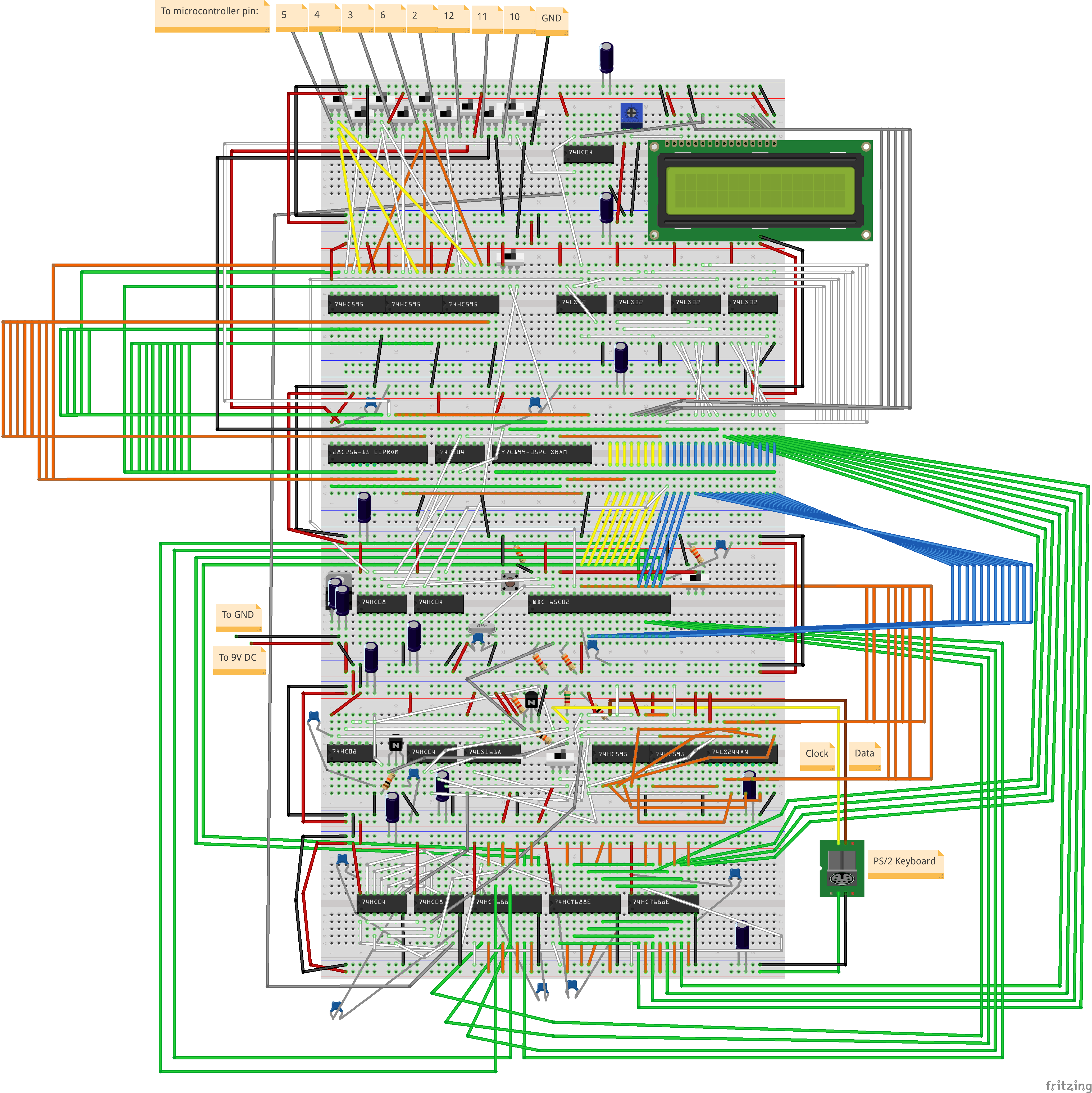
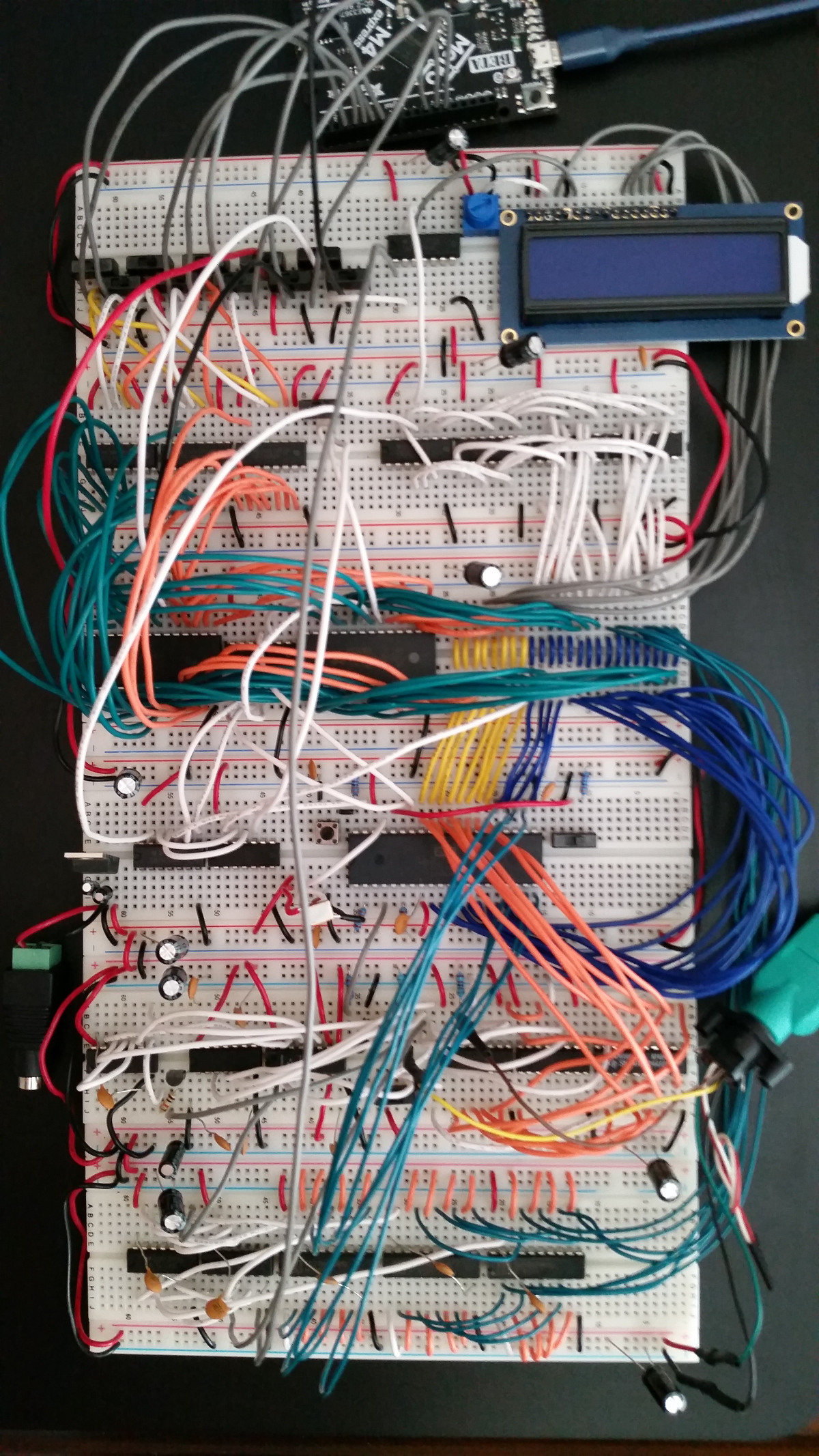
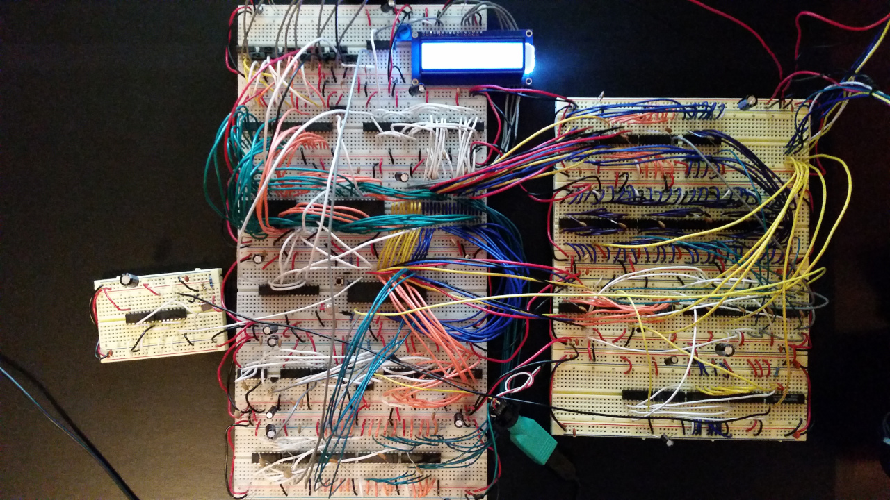
“Nick Bild” has built a custom 6502-based computer that anyone could replicate. Get the parts listed in the bill of materials, open the Fritzing diagram, start plugging in and wiring chips, and you can have your own Vectron 64 in a weekend! It may seems a little complicated on the first sight but remember this was one of the first computers in the PC era and now you can build one yourself. With a little practice and much patience you can have a working 6502 based computer.
To demonstrate the system, They have developed the 3D game “Asteroids VR“. Put the headset on and you’ll be sitting in the 3D cockpit of a spaceship blasting away at asteroids that appear to be floating towards you.
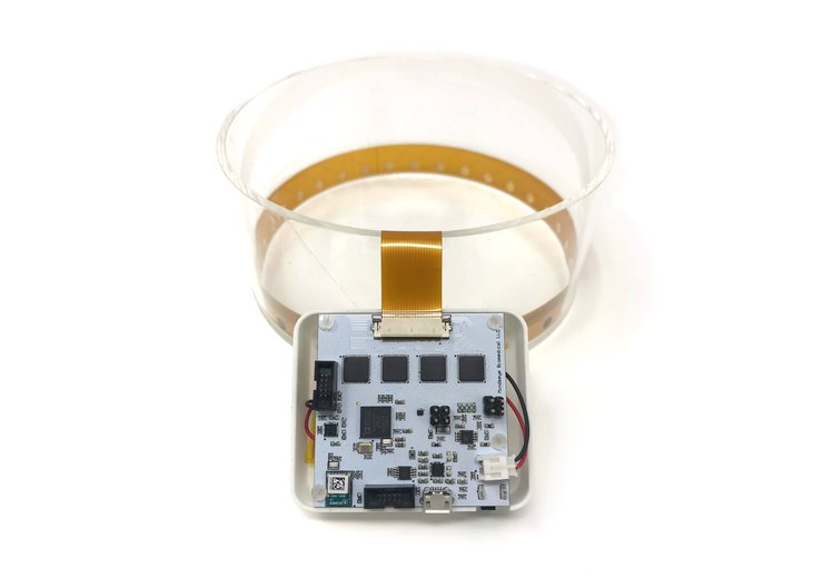
Spectra brings open source biomedical imaging into the open with a development kit that is both safe and easy to use. It allows hackers and scientists to experiment with one of the technologies used in medical imaging — electrical impedance tomography (EIT). For the first time, anyone who wants to explore the fascinating world of medical physics can do so from their own home, without a multimillion-dollar CATSCAN.
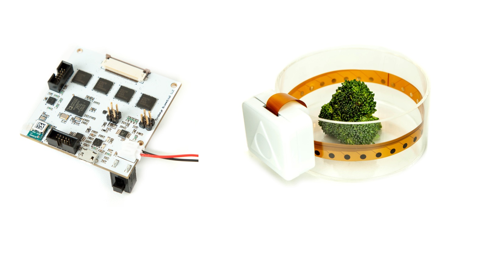
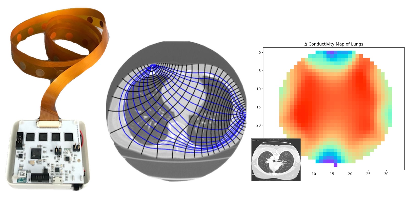
Electrical Impedance Tomography (EIT) can localize dielectric changes in the body such as lung changes or by used for gestural control. The Spectra device is wrapped around the thorax to map changes in the lungs. It can track lung volume, expansion and contraction in real-time of each lung individually alongside impedance cardiography of blood flow through heart valves.
Spectra can image lungs, monitor heart activity, and detect changes on materials like bones, tumors and strawberries. Since it can get a cross-section of whatever it’s wrapped around it’s also ideal for gestural recognition and could be used to help those with prosthetic limbs.
Features & Specifications
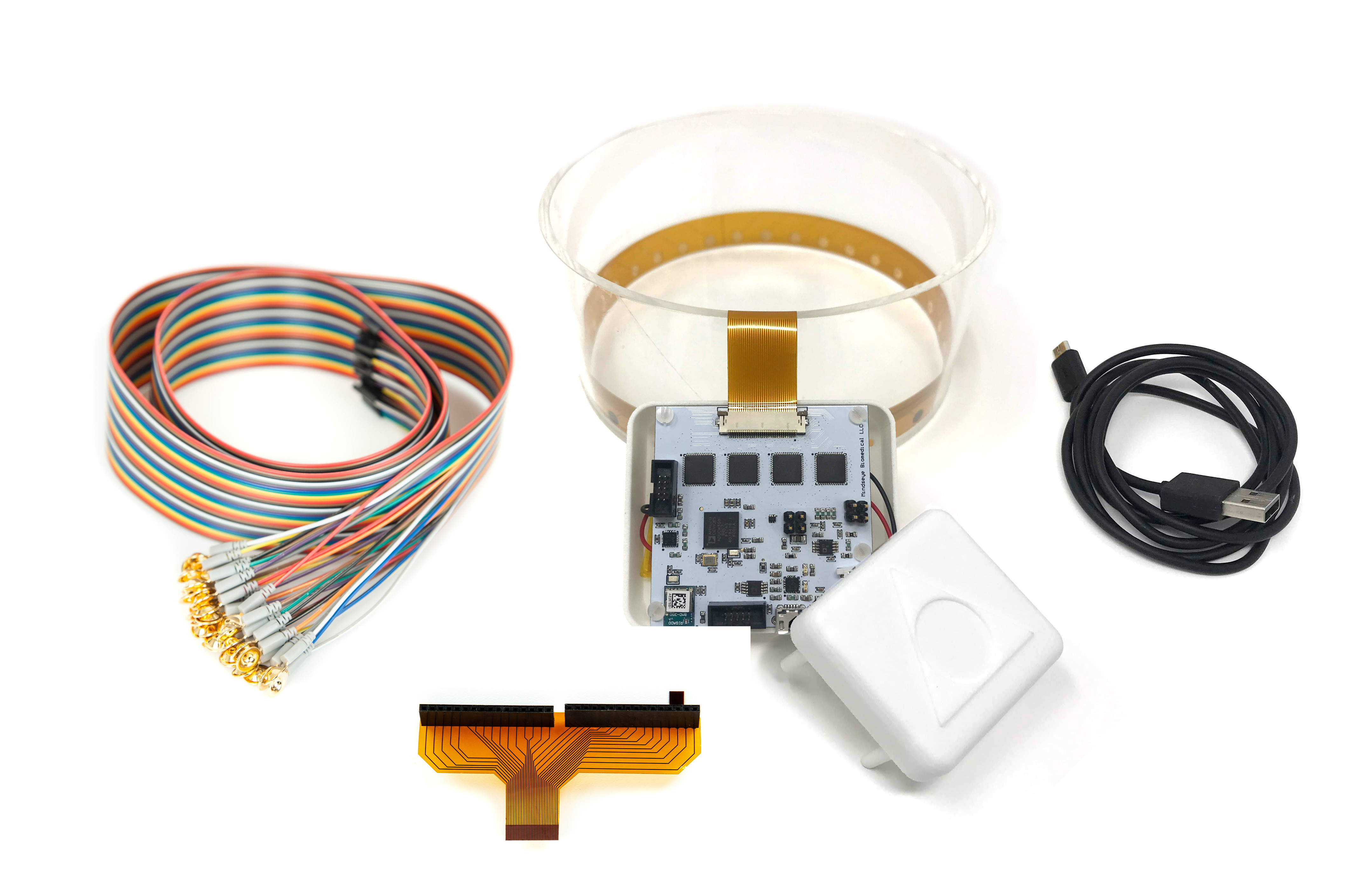
Precise and highly configurable sensor hardware
Can be configured to use up to 32 electrodes.
Measures at 160,000 samples per second.
Each impedance measure is made using differential referencing and 16-bit resolution.
Includes automatic temperature calibration to ensure impedance accuracy.
Includes an accelerometer for motion mitigation.
Built for safety and ease-of-use
DC power removal filters meet IEC60601-1 safety specifications.
Compatible with a 3.5 V, 850 mAh battery (not included) for improved portability. On-board circuitry allows charging via the supplied USB cable. Up to 12 hours of battery life, depending on the specific use case.
Support for Bluetooth Low Energy (BLE) to accommodate wireless data transmission.
Flexible open source software
Easy to install software supports time series impedance measurements, bio-impedance spectroscopy, and electrical impedance tomography, between 80 Hz and 80 kHz, with up to 32 electrodes.
Supports three different types of tomographic reconstruction: Graz Consensus, Gauss-Newton Method, and Back Projection. All three can be run in realtime and can be configured with any number of electrodes (e.g., 8, 16, or 32). You can record for analysis offline, and run in real-time.
Hardware includes Serial Wire Debug (SWD) programmers for easy firmware re-programming.
Portable design
Tiny, portable PCB measures approximately 2” by 2” and comes with a plastic enclosure.
Comes with a small, cylindrical ‘phantom’ tank (140 mm diameter, 60 mm height).
Comes with a flexible electrodes for imaging things that don’t fit in the phantom.
The project is live on Crowdsupply.com and has 24 days to go. Spectra Starter Kit sells at $299.
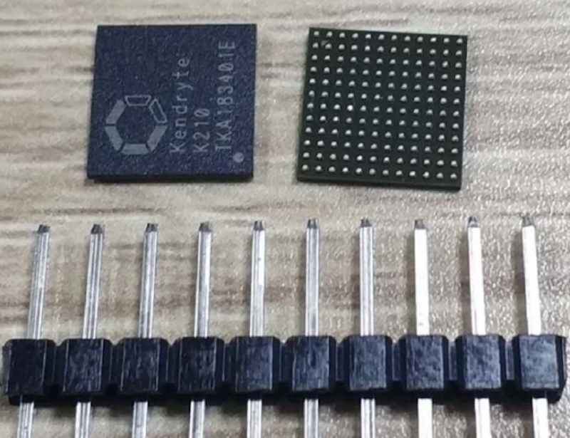
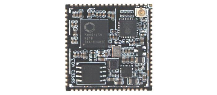
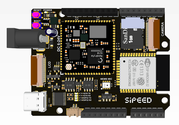
Sipeed released their 64-bit RISC-V MAix module at the end of last year, crowdfunding a series of boards on Indiegogo built majorly to do machine learning inferencing at the edge, with no cloud needed. There has been a lot of work put in, to document and support the MAix module, including both Arduino support and a port of MicroPython. Sipeed’s Maixduino is a MAix-based board that features a “classic” Arduino form factor which is pin-compatible to the Arduino. The board is designed based on two processor modules, Sipeed’s RISC-V MAix module, and an Espressif ESP-WROOM-32. Sipeed’s MAix module is based on the Kendryte K210 processor, that features two 64-bit RISC-V CPU cores, both with a built-in independent FPU, and 8Mb of SRAM.
The Sipeed MAix module.
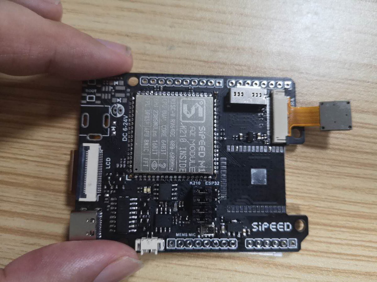
The K210 has an onboard neural network processor (KPU) for supporting machine vision applications at up to 60fps for QVGA, and 30fps for VGA. Also available is an audio processor (APU) which supports up to eight microphones at up to 192KHz, with Fast Fourier Transform (FFT) hardware acceleration. It also includes a 16MB Flash and Wi-Fi support via an on-module Espressif ESP8285. When you flip the Maixduino over, it shows a basic wiring diagram of how the board’s two processor modules communicate with one another— that is an interesting addition. The ESP32 pins are broken out to include ADC support which the K210 lacks.
Render of the finished Maxduino board.
This suggests that it’s also available for other tasks, as it’s there as a co-processor. The board is powered through a USB-C socket instead of the conventional micro USB. For the silkscreen feature, there is likely provision for a barrel jack which can take 6 to 24V DC as input, although it’s unknown if this is going to be populated on the final board. The board possesses a single channel speaker PA onboard, enabling you to connect a 1 to 3W speaker, with a single I2S microphone offering keyword recognition support. A micro SD card slot and both an LCD display and camera connectors are available.
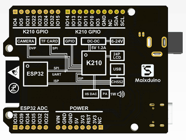
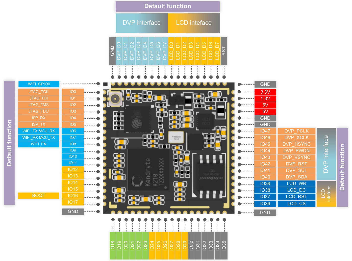
The MAix module pin out.
Development for the board can be done either in MicroPython, or in the Arduino development scene. The Arduino port enables full support for the neural network API, and inclusive of an object detection demo inferencing example using MobileNet v1. Support for the OpenMV development environment will be available soon. Full details about the Maixduino haven’t been announced officially yet, but it will be released later this week. Also, there isn’t a precise price point, but the MAix module itself retails in small numbers for around $5, So the Maixduino might cost somewhere between $20 and $30.
v0.2 MaixDuino sample come out~ Change to CH552 dual serial chip, download for K210&ESP32 independent. pic.twitter.com/SitymRwkXv
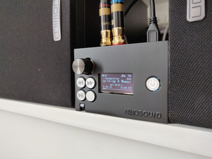
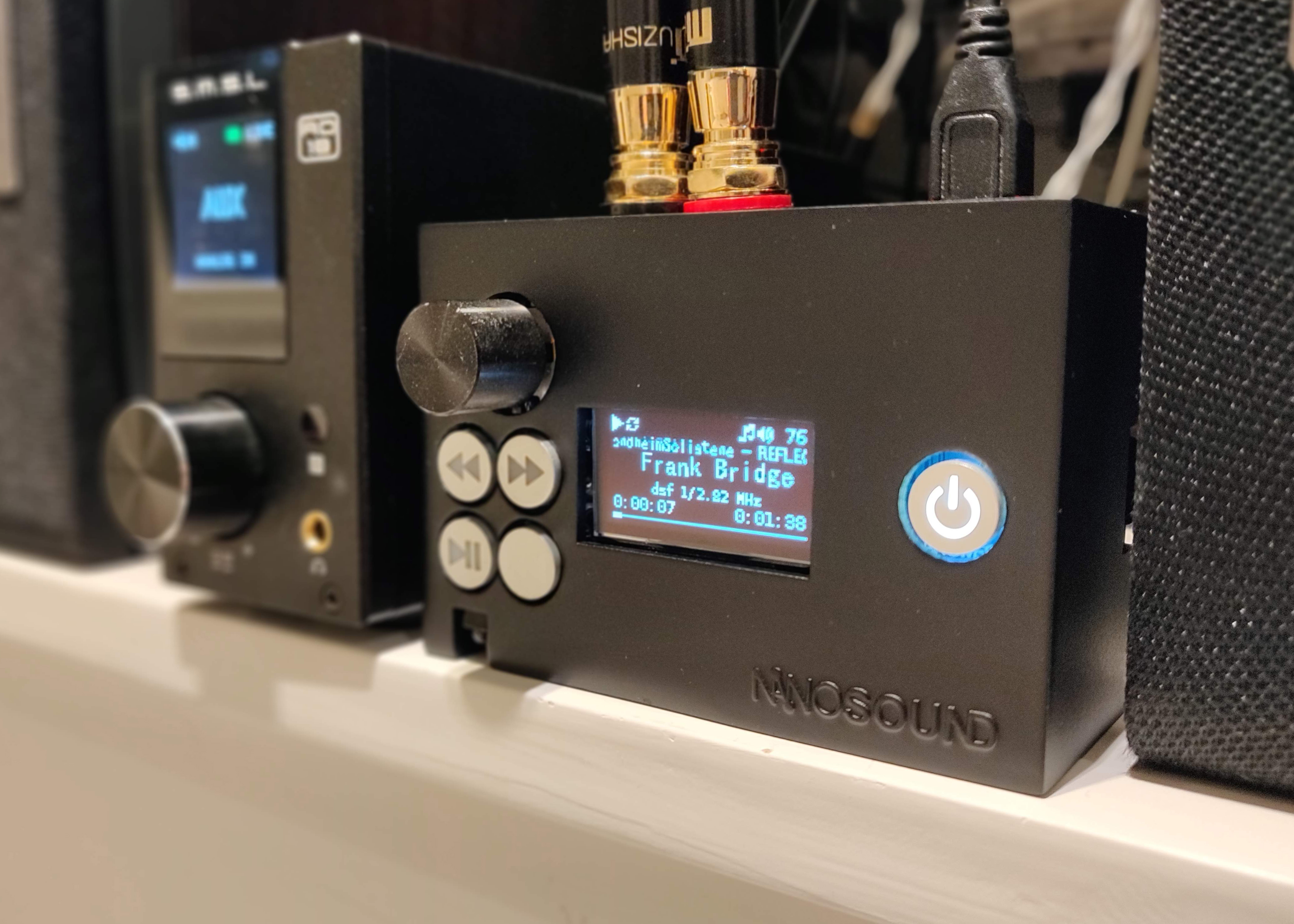
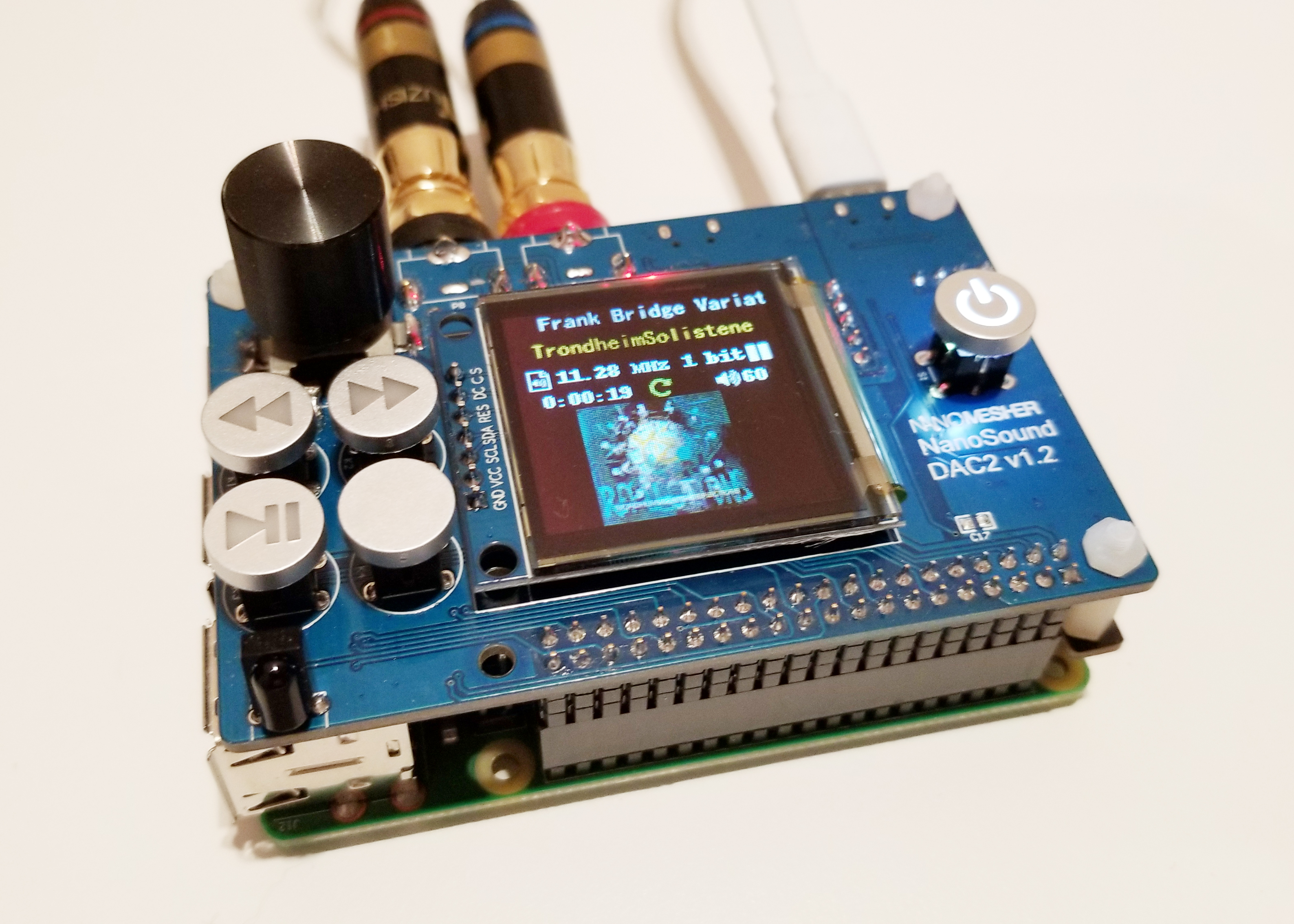
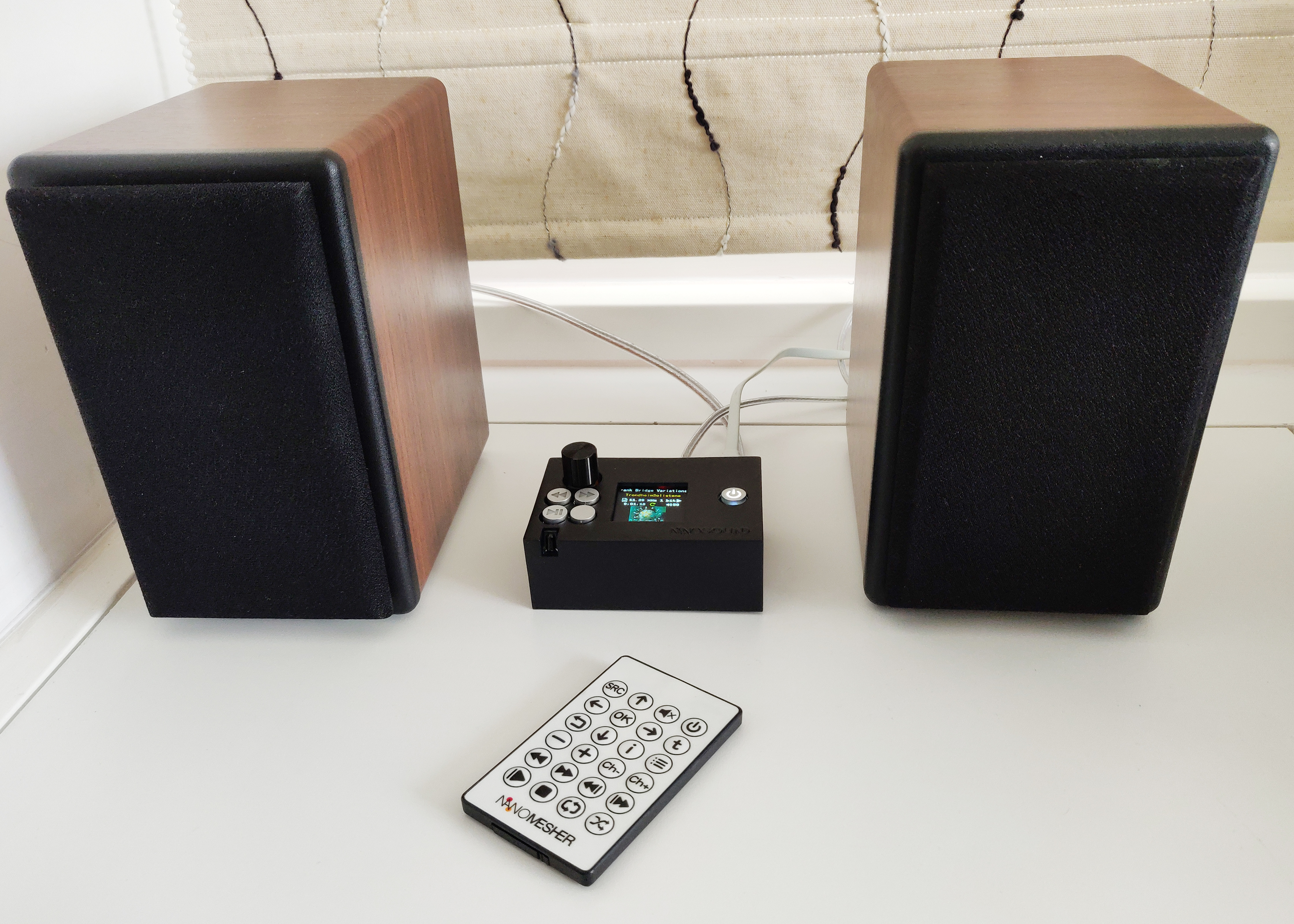
NanoSound DAC 2 – World’s first Raspberry Pi DAC with Colour OLED display, onboard dual clock, improved sound quality and much more.
The original NanoSound DAC is one of the most successful Pi Audio Products launched via Kickstarter, with 274 very satisfied backers and delivery on time. NanoSound DAC is a Raspberry Pi Add-on Board with HIFI DAC, LDO Voltage Regulator, OLED Display, Power Switch, Control Buttons and Infrared Remote.