Vishay’s new VCNL4040 fully integrated proximity and ambient light sensor

Features Filtron™ technology; three-in-one design combines IR emitter, photo detectors, signal processing IC, 16-bit ADC   

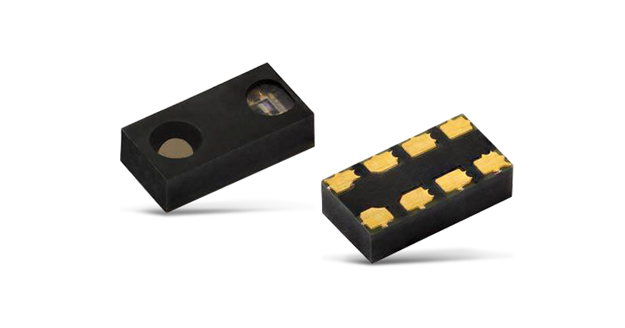
Vishay’s new VCNL4040 fully integrated proximity and ambient light sensor is now available from TTI, Inc., a world leading specialist distributor of electronic components. Featuring Filtron™ technology, the VCNL4040 combines an IR emitter, photo detectors for proximity and ambient light, a signal processing IC and a 16-bit ADC.  The new device is offered in one of the market’s smallest surface-mount packages, at only 4mm x 2mm x 1.1mm.  The three-in-one sensor features an interrupt function and supports an I²C bus communications interface, which significantly simplifies window and sensor placement.  Suitable applications for the VCNL4040 include home automation, consumer devices, industrial applications, handheld devices, notebooks and tablets.
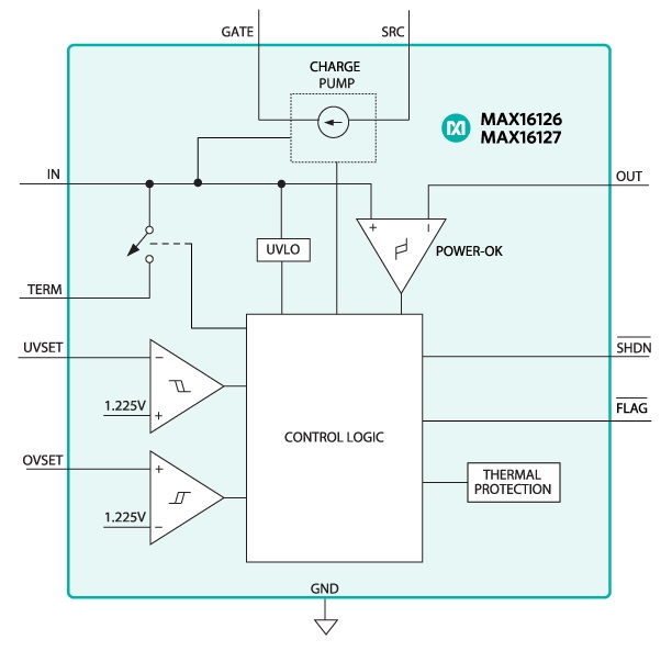
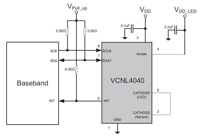
Block diagram

The highly accurate ambient light sensor (ALS) offers 16-bit high resolution with sufficient selections to suit the demands of most applications, whether dark or high transparency lens design. Patented Filtron™ technology achieves ambient light spectrum sensitivity close to real human eye responses, with fluorescent light flicker immunity.  The proximity function offers immunity to red glow (940nm IRED) and has an intelligent cancellation scheme that effectively reduces crosstalk and a smart persistence scheme to reduce response time. Both the ALS and proximity sensor (PS) operate in parallel, and can be programmed for high and low interrupt thresholds, so only using minimal amount of microprocessor resource.

Features

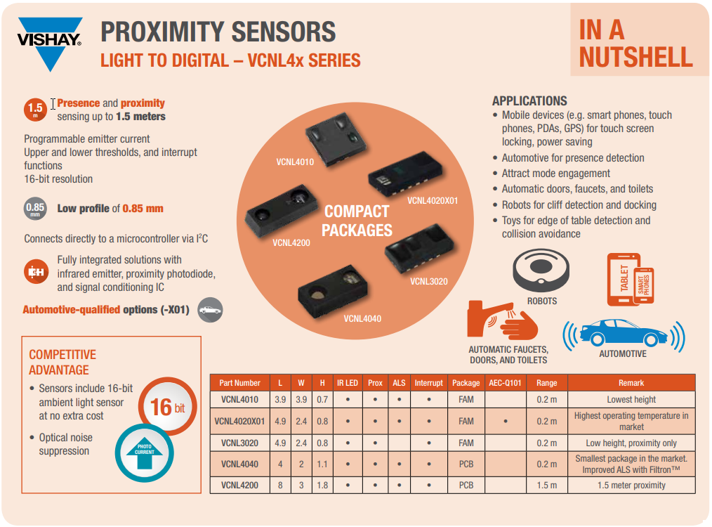
  • Detection range up to 20cm
  • 12-bit or 16-bit proximity sensor resolution
  • 16-bit ambient light sensor resolution
  • Elimination of cross-talk
  • Tiny package of 4.0×2.0x1.1mm height
  • I2C protocol (SMBus compatible) interface
  • Emitter forward current
  • Proximity resolution
  • Four selectable lux ranges
  • Interrupt with upper and lower thresholds
  • Power on, shutdown

Other specifications include operating voltage between 2.5V to 3.6V, temperature compensation of -40deg.C to +85degC. and a low power consumption I²C SMBus compatible interface.

Further information is available on www.vishay.com

Dual-Channel, 42 V, 4 A Monolithic Synchronous Step-Down Silent Switcher 2

The LT8650S 42 V, dual-channel, 4 A synchronous Silent Switcher® 2 regulator features a wide input voltage range of 3 V to 42 V, ideal for automotive, industrial, and other step-down applications. Its quiescent current is only 6.2 µA with the outputs in regulation – a critical feature in automotive environments where always-on systems can drain the battery even when the car is not running. In many switching regulator designs, EMI can be a problem if the board layout does not adhere to stringent layout standards. This is not the case with a Silent Switcher 2 design, where automotive EMI standards are easily passed with minimal layout concerns.

7.5 V/4 A and 3.3 V/4 A Outputs Have a Fast Transient Response

Figure 1 shows a dual output regulator designed to optimize the transient response. Although the LT8650S includes internal compensation, external compensation is used to minimize the transient response time and output voltage excursions. Switching is at 2 MHz, allowing higher loop bandwidth and a faster transient response.

Figure 1. 7.5 V/4 A and 3.3 V/4 A outputs feature fast transient response.

Figure 2 shows the output response to a 0 A to 4 A load step, where VOUT drops less than 100 mV for both the 3.3 V and 7.5 V outputs. This response is combined with high initial accuracy for a solution that meets tight VOUT tolerance.

Figure 2. 0 A to 4 A transient responses of the circuit in Figure 1
(Burst Mode operation).

Paralleled Outputs Deliver 9 V/8 A from 24 V While Remaining Cool

The LT8650S packs two synchronous step-down regulators into a 4 mm × 6 mm package. The two outputs can be easily paralleled for high current as shown by the 72 W output, 24 V input design in Figure 3. Efficiency at full load is 95%, with the thermal performance of the board shown in Figure 4. Running at room temperature, the hottest part of the IC reaches about 75 °C without active cooling.

Figure 3. Paralleled outputs deliver 9 V/8 A from a 24 V input while remaining cool.

The temperature and efficiency are even better for a 12 V input. When paralleling, it is important to balance the current between the outputs by tying the outputs of error amplifiers together. This can be achieved by connecting VC1 and VC2 together and using external compensation. For applications that require a larger thermal budget, the LT8650H operates with a junction temperature.

Figure 4. Thermal performance of the circuit in Figure 3.

3.3 V/3 A and 1 V/5 A Running at 2 MHz for an SoC Application

Many system on a chip (SoC) applications require 3.3 V for peripherals and 1 V for the core. Figure 5 shows the LT8650S used in a cascade topology, where the input for the 1 V converter is powered by the 3.3 V output. There are a number of benefits of a cascade configuration over powering VIN2 from the main supply, including reduced solution size and constant 2 MHz operation.

Figure 5. 3.3 V/3 A and 1 V/5 A circuit running at 2 MHz for a SoC application.

The 4 A current rating per channel of the LT8650S is based on thermal limitations, but each channel can electrically deliver 6 A if temperature rise is managed with additional cooling. In the solution of Figure 5, the output power of the 1 V channel 2 is low, so it can deliver 5 A.

Conclusion

The LT8650S features a wide input range, low quiescent current, and Silent Switcher  design. Packing two 4 A synchronous step-down regulators in a 4 mm × 6 mm package reduces part count and solution size while allowing design flexibility for a broad range of applications.

via analog.com

Arbor’s “EmQ-RK390” Qseven module runs Linux or Android on a Rockchip RK3399

ARBOR Technology, a leading provider of embedded computing solutions, which featured this year on concluded Embedded World 2019 Exhibition that took place in Nuremberg, Germany has launched the EmQ-RK390 Qseven module which is based on the RK3399-based SoC. The Qseven concept is an off-the-shelf, multi-vendor, Computer-On-Module that integrates all the core components of a standard PC and is mounted onto an application specific carrier board.

The EmQ-RK390 Qseven module was announced during the event and even displayed at their booth. The launch of the EmQ-Rk390 will be a new direction from Arbor due to the presence of the RK3399 SoC as compared to the previous Intel Apollo Lake-based modules. The RK3399 SoC has dominated the single board computers market for a while with several boards released.

SoM-RK290
EmQ-RK290 Qseven Module

Arbor’s EmQ-RK390 Qseven module runs Linux-Ubuntu, Builtroot and Android 8.1 on an onboard Rockchip RK3399 Dual-core Cortex-A72 clocked up to 2.0GHz. It also comes with an additional Quad-core Cortex-A53 processor running up to 1.42GHz. The board comes with an inbuilt 2GB LPDDR3 SDRAM and support for an optional 4GB with soldered 16GB eMMC memory. Just like most other RK3399 based boards, this board also features a high-end, quad-core Mali-T864 GPU.

The board dimensions is in line with Qseven standardized form factor of 70mm x 70mm. At -20 to 70°C temperature, the EmQ-RK390 module is tailored to work in the most demanding industrial environment. Although it doesn’t come with an onboard wireless card, it comes with a USB-based RTL8153B GbE controller and a PCIe x4 interface for connecting to the internet or some other network system.

EmQ-RK390 board – top view

It also comes with a dual-channel 24-bit LVDS, and HDMI media interfaces. A 2x MIPI-CSI camera interface (4 x lanes + 2 x lanes) is also available and there is also a I2S audio interface. The board supports 8-bit GPIO, SDIO, I2C, 4x USB 2.0, 5x UART, and a single USB 3.0 port. The 5V EmQ-RK390 module provides an extra humidity resistance something you don’t always find around, as well as an optional heat spreader, heatsink, and cable kit.

Introduction Video

The ARBOR’s SOM-RK391 embedded board provides extraordinary computing power with a high-performance GPU combined with an efficient CPU allowing for intensive applications such as AI computing, edge computing and machine vision to be implemented in practical scenarios with ARM-Based computing platform.

No information is available about product pricing, and little information is available about the product. More information is found on the announcement page, the product page, and the product datasheet.

Giant Board – A single-board computer in the Adafruit Feather form factor

Giant Board is an Open Source, Linux-capable SBC Compatible with the Featherwing Ecosystem.

The Giant Board will come with over 100 CircuitPython libraries pre-installed and support many popular FeatherWings. Linux drivers interface directly with the Ethernet and LCD FeatherWings, and they can be easily enabled or disabled via a simple text file. Most FeatherWings will work out of the box with Adafruit’s CircuitPython example code.

Giant Board (bottom)

Features & Specifications

  • Processor: Microchip SAMA5D2 ARM® Cortex®-A5 Processor 500 MHz
  • Memory: 128 MB DDR2 RAM
  • Storage: microSD card
  • Sensing: 6 x 12-bit ADC with 3.3 V reference and external trigger
  • Actuation: 4 x 16-bit PWM with external trigger
  • Connectivity: 1 x I2C, 1 x SPI, 1 x UART, more with Flexcom
  • Power: via USB, with support for LiPo batteries
  • Operating System: mainline Linux kernel
Giant Board Pin Out

Low-power Modes

The Giant Board has support for four low-power modes, each of which supports a different wake up mechanism:

  • standby with GPIO button wake up
  • standby with RTC wake up
  • memory suspend with ‘power on’ button wake up
  • memory suspend with RTC wake up

The project is soon going to launch on crowdsupply.com. You can subscribe to the list to get notifications.

UPDATE 11/02/2020

The Giant board is now in production and to help promote it they are hosting a design contest. They are offering a free board for people that want to participate in the contest.

We’re thrilled to announce that we’ve partnered with Microchip for another contest! Last time, we received a slew of neat projects such as an IoT incubator, domestic central heating radiator optimiser, and the pick a plant! This time around, we’re once again excited to see what creative projects you come up with.

Entering is simple. Just come up with a unique project idea that incorporates the Giant Board and submit your idea to us using 150 words. Once you receive your board you can start building your project while using the Electromaker platform to document your build along the way. We will then judge all submitted project entries and award the cash prizes. The timeline can be found at the bottom of this page.

USB Stack Light Controller based on PIC16F1459

Glen Akins build a USB Stack Light Controller based on PIC16F1459 and documents the process on this personal blog. He writes:

After using the PIC16F1459 to build numerous USB HID input devices including a giant keyboard, a tiny keyboard, and a big red button, it was time to see if the PIC16F1459 could be used to control outputs too. Sticking with the industrial theme, I chose to build a USB controller for a, um, stack of industrial stack lights.

[…]

Now that the enclosure and PCB size were finalized it was time to design the electronics. One requirement was to be able to fade the stack lights in and out and control their brightness. The PIC16F1459 only has two hardware PWM channels though. To PWM three different colored stack light segments would require external hardware or some crafty software techniques. I decided to throw hardware at the problem.

USB Stack Light Controller based on PIC16F1459 – [Link]

AMD expands Embedded Product Family with New Ryzen™ Embedded R1000

The AMD Ryzen™ Embedded R1000 SoC provides a new class of performance for the embedded industry with 3X performance per watt vs. previous AMD R-Series SoC1 and 4X performance per dollar compared to the competition.

At the Taiwan Embedded Forum, AMD announced the Ryzen™ embedded product family is growing with the new AMD Ryzen™ Embedded R1000 SoC. Building upon the success of the Ryzen™ Embedded V1000 SoC, the AMD Ryzen Embedded R1000 SoC provides embedded customers with dual core, quad-threaded performance, as well as the ability to run fanless, low power solutions for 4K displays; while providing leading-edge security features. The AMD Ryzen Embedded R1000 is perfect for applications in digital displays, high-performance edge computing, networking, thin clients and more.

Customers like Advantech, ASRock Industrial, IBASE, Netronome, Quixant and others are already working on Ryzen Embedded R1000-based products. As well, Atari© is using the high-performance Vega 3 graphics and ‘Zen’ CPU architecture in the AMD Ryzen Embedded R1000 SoC to power the upcoming Atari VCS™ game system.

The AMD Ryzen Embedded R1000 builds out the Ryzen Embedded family and provides a compelling option for customers that want access to the powerful ‘Zen’ and ‘Vega’ architecture and are looking for a highly competitive power/performance solution,

said Stephen Turnbull, director of product management and business development, Embedded Solutions, AMD.

The Ryzen Embedded R1000 can support rich multimedia environments for digital displays and casino gaming, enterprise class security features for edge computing, networking and thin clients, and, most importantly introduces a new class of performance while providing customers with software and hardware compatibility with the extended Ryzen Embedded family.

Growing the Ryzen Embedded Family

The AMD Ryzen Embedded R1000 continues to provide the embedded industry with the high-performance, rich multimedia capabilities and advanced security features established with the Ryzen Embedded V1000.

Specifically, as the embedded industry demands more immersive and engaging visual experiences, customers need processors that can support high-resolution displays with demanding graphics. The AMD Ryzen Embedded R1000 supports up to three 4K displays at up to 60 FPS, while providing H.265 Encode/Decode(10b) and VP9 decode3 capabilities. This enables OEMs and ODMs to deliver a compelling visual experience.

As well, the Ryzen Embedded R1000 utilizes the same leading-edge security features of the AMD embedded family, including Secure Root of Trust and Secure Run Technology, giving customers the features for enabling secure solutions, whether they are connected into an edge computing network, or running a digital display.

Availability

The AMD Ryzen Embedded R1000 will be available this quarter to ODMs and OEMs worldwide and is already supported by numerous hardware and software companies including Advantech, Alphainfo, ASRock Industrial, Axiomtech, DFI, iBase, Kontron, MEN, Mentor, Sapphire, zSpace and more.

As well, continuing a great partnership between the two companies, the AMD Ryzen Embedded R1000 SoC supports the Mentor® Embedded Linux® Flex OS, which is available now. You can read more here.

MAX16126/MAX16127 – protect power-supply inputs from automotive voltage transients

MAX16126/MAX16127 – protect power-supply inputs from automotive voltage transients, including load dump

The MAX16126/MAX16127 load-dump/reverse-voltage protection circuits protect power supplies from damaging input voltage conditions, including overvoltage, reverse-voltage, and high-voltage transient pulses. Using a built-in charge pump, the devices control two external back-to-back n-channel MOSFETs that turn off and isolate downstream power supplies during damaging input conditions, such as an automotive load-dump pulse or a reverse-battery condition. Operation is guaranteed down to 3V to ensure proper operation during automotive cold-crank conditions. These devices feature a flag output (active-low FLAG) that asserts during fault conditions.

For reverse-voltage protection, external back-to-back MOSFETs outperform the traditional reverse-battery diode, minimizing the voltage drop and power dissipation during normal operation.

The MAX16126/MAX16127 use external resistors to adjust the overvoltage and undervoltage comparator thresholds for maximum flexibility.

The MAX16127 provides limiter-mode fault management for overvoltage and thermal shutdown conditions; whereas the MAX16126 provides switch-mode fault management for overvoltage and thermal shutdown conditions. In the limiter mode, the output voltage is limited and active-low FLAG is asserted low during a fault. In the switch mode, the external MOSFETs are switched off and active-low FLAG is asserted low after a fault. The switch mode is available in four options: latch mode, 1 autoretry mode, 3 autoretry mode, and always autoretry mode.

The MAX16126/MAX16127 are available in 12-pin TQFN packages. These devices operate over the automotive temperature range (-40°C to +125°C).

Key features

  • Increases Protection of Sensitive Electronic Components in Harsh Environments
    • -36V to +90V Wide Input-Voltage Protection Range
    • Fast Gate Shutoff During Fault Conditions with Complete Load Isolation
    • Thermal-Shutdown Protection
    • Active-Low FLAG Output Identifies Fault Condition
  • AEC-Q100 Automotive Qualified
    • Operates Down to +3V, Riding Out Cold-Crank Conditions
    • -40°C to +125°C Operating Temperature Range
  • Integration Reduces Solution Size
    • Internal Charge-Pump Circuit Enhances External n-Channel MOSFETs
    • Adjustable Undervoltage/Overvoltage Thresholds
    • 3mm x 3mm, 12-Pin TQFN Package
  • Reduced Power Dissipation Compared to Discrete Solutions
    • Minimal Operating Voltage Drop for Reverse- Voltage Protection
    • 350µA (max) Supply Current and 100µA (max) Shutdown Current at 30V Input

Applications

  • Automotive
  • Avionics
  • Industrial
  • Telecom/Server/Networking

Block Diagram

more information here: www.maximintegrated.com

Western Digital PC SA530 3D NAND SATA SSD

Up to 1TB capacity for exceptional storage options for a broad range of computing applications

High performance and high capacity for computing

The Western Digital PC SA530 combines Western Digital’s state-of-the-art 96-layer 3D NAND technology with the proven SSD platform. It also incorporates nCache™ 2.0, a tiered caching technology designed to improve responsiveness for corporate and consumer workloads. nCache 2.0 uses a combination of both SLC (single level cell) and TLC flash blocks to improve endurance, increase efficiency, and boost performance.Writing data first to the SLC cache reduces write amplification on the TLC blocks.

With on-the-fly hardware-based encryption, the Western Digital PC SA530 (SED models only) provides complete end-to-end encryption to the storage, system and infrastructure. It supports password protection, AES-256-bit encryption, TCG-OPAL 2.01 standard and PSID.

Specifications

Highlights

  • Western Digital 96-layer 3D NAND delivers capacities up to 1TB
  • 2.5″/7mm cased or M.2 2280 form factors
  • Leading-edge SATA performance up to 560 MB/s sequential read

Applications and Workload

  • Desktop and Laptop Computers
  • Ultra-Thin Notebooks and Tablets
  • Interactive Applications
  • Industrial Applications
  • Media and Entertainment Applications

15A 100V Isolated Half-Bridge Driver

15 A 100V Isolated Half bridge driver project intended to be used for DC-DC converters, inverters, LED driver and motor driver applications. This projects is really helpful in industrial applications where noise is a concern since project provides optical isolation between microcontroller and high current output. ADuM4224 isolated precision Half-Bridge driver is the heart of the project. IRFR120 dual Mosfet is used as output driver. MOSFET can be replaced as per application requirement of voltage and current rating. The ADuM4224 isolators each provide two independent isolated channels. They operate with an input supply voltage ranging from 3.0 V to 5.5 V, providing compatibility with lower voltage systems. In comparison to gate drivers employing high voltage level translation methodologies, the project offers the benefit of true, galvanic isolation between the input and each output. Each output can be continuously operated up to 537 V peak relative to the input, thereby supporting low-side switching to negative voltages. The differential voltage between the high-side and low-side can be as high as 800 V peak. Refer to truth table for operation conditions. The board tested with input frequency of 100 KHz but will support frequency up to 1 MHz. CN3 connector provided for logic signal and supply input, CN1 Output drive supply , CN2 load supply input, CN4 for load connection.

15A 100V Isolated Half-Bridge Driver – [Link]

Programmable USB Hub will soon launch on Crowdsupply

A USB hub that’s also a dev board and an I2C, GPIO, and SPI bridge.

In addition to being a 4-port USB 2 High-Speed hub, this Programmable USB hub is also:

  • A CircuitPython based development board.
  • A bridge between your computer and I2C (via Sparkfun Qwiic connectors), GPIO, and SPI (via its mikroBUS header).
  • A power supply, providing 6 A of 5 V power to downstream devices and 13 mA resolution monitoring (per-port).
  • A USB to TTL Serial adapter.
  • A flexible embedded electronics test and development tool.
  • Mountable.
  • Functionally flexible. Open source python drivers on the upstream host and Python firmware on the internal MCU allow the behavior of this USB hub to be easily changed to suit your application and environment.

The Capable Robot Programmable USB hub is housed in a robust extruded aluminum enclosure.

Internally mounted LED light pipes direct status information from 10 RGB LEDs to the front panel for easy observation of hub state.

The rear of the enclosure exposes the upstream USB connection and a USB port to re-program and communicate with the internal MCU. Also exposed are two I2C buses (via Sparkfun Qwiic connectors), the Programmable USB hub’s UART, and 2x GPIO. Input power is provided to the hub by a locking Molex Micro-Fit connector.

Features and Specifications

  • USB2 High-Speed Hub
    • 4x USB2 High Speed (480 mbps) downstream ports
    • 1x USB2 High Speed (480 mbps) upstream port
    • 5th endpoint on USB hub exposes I2C, SPI, UART, and 2x GPIO
    • Data lines to each USB port can be disconnected via software commands. This allows errant USB devices to be “unplugged” virtually and re-enumerated.
    • USB digital signals can be boosted to help drive long cables.
  • Power Monitoring & Control
    • 5 V power on each downstream port can be individually turned on and off
    • Monitor the power consumed by each port at up to 1 kHz at a resolution of 13 mA
    • Adjustable (per-port) current limits between 0.5 A and 2.6 A
    • Onboard regulators support 12 V to 24 V power input and generate 6 A of 5 V power for downstream devices. No power is drawn from the upstream USB port.
    • Input power is protected from over-voltage events and reverse-polarity connection.
  • Physical IO
    • mikroBUS header to add additional sensors and connectivity. Solder jumpers enable the UART and SPI to connect to either the USB hub IC or the MCU.
    • JST GH connector with UART and 2x GPIO, controlled by the USB hub.
    • 2x Sparkfun Qwiic connectors enable easy attachment of I2C sensors to the USB hub or to the internal MCU.
    • 5x RGB status LEDs to visualize port power draw
    • 5x RGB status LEDs to visualize port connection types
  • Open Source Python Drivers
    • MIT-licensed Python drivers allow you to control and monitor your USB hub the way you want to.
    • Easy integration into hardware-in-the-loop (HITL) test systems
    • Automate testing of embedded USB devices. You can simulate USB unplug events, unexpected loss of USB power, control.
    • Control and monitor the USB hub via the upstream USB port or the MCU USB port.
  • Runs Adafruit CircuitPython
    • An ATSAMD51 microcontroller configures the USB hub IC and is available for you to reprogram to change the behavior of your hub.
    • The microcontroller ships with open source CircuitPython firmware which is updatable over the MCU USB connector. No drivers or reflashing hardware is needed – Python firmware shows up as files on a small flash hard drive when connected to your computer and can be immediately edited.
  • Robust Design
    • Extruded aluminum enclosure with optional rubber bumper end caps and optional flange mounts.
    • OEM version (board only) has corner mounting holes for easy integration into a custom enclosure.
    • IO is protected from ESD strikes (exact specification TBD).
    • Locking input power connector with reverse polarity protection and over-voltage protection
    • Reinforced Micro-USB connectors

The project is soon going to launch on CrowdSuppy.com

TOP PCB Companies