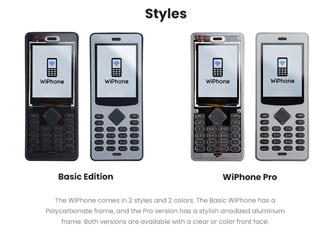
WiPhone is a VoIP mobile phone designed for hackers and makers to be easily modified, repurposed, and adapted.
WiPhone is a unique, minimal phone. It’s designed to enable hackers by making it easy to extend and modify the electronics and software. Something typical phones are not good for. WiPhone is also a VoIP mobile phone. It uses WIFI to make HD voice calls, for free. This means that there is no required service contract – and it’s yours for life.
[…]
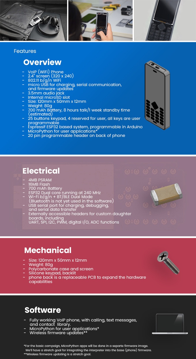
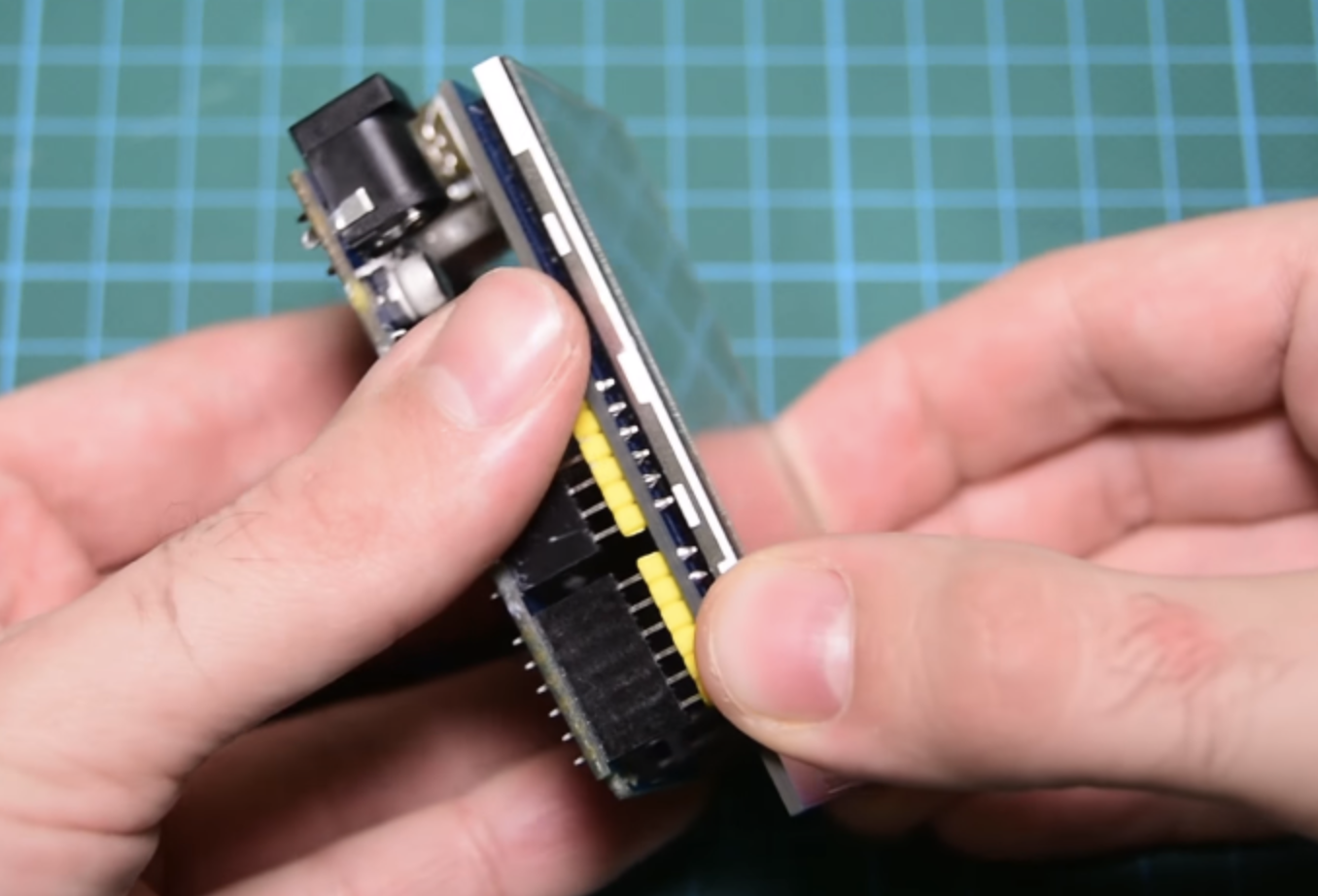
WiPhone solves these problems and gives hackers, makers, and engineers the tool we all wish our phones could be. Nice package, direct access to I/O, an easy to program ESP32 processor. All the basics are already set up: user interface, power management and on/off circuit, working code.
The project is live on kickstarter, is already funded and has 7 days to go.
Displaying a custom image or graphic on a LCD display is a very useful task as displays are now a premium way of providing feedback to users on any project. With this functionality, we can build projects that display our own logo, or display images that help users better understand a particular task the project is performing, providing an all-round improved User Experience (UX) for your Arduino or ESP8266 based project. Today’s tutorial will focus on how you can display graphics on most Arduino compatible displays.
The procedure described in this tutorial works with all color displays supported by Adafruit’s GFX library and also works for displays supported by the TFTLCD library from Adafruit with little modification. Some of the displays on which this procedure works include:
While these are the displays we have, and on which this tutorial was tested, we are confident it will work perfectly fine with most of the other Arduino compatible displays.
For each of the displays mentioned above, we have covered in past how to program and connect them to Arduino. You should check those tutorials, as they will give you the necessary background knowledge on how each of these displays works.
For this tutorial, we will use the 2.8″ ILI9325 TFT Display which offers a resolution of 320 x 340 pixels and we will display a bitmap image of a car.
2.8″ ILI9325 TFT Display
Required Components
To demonstrate how this works with different displays, you can use some of the most popular displays:
As usual, each of the components listed above can be bought from the links attached to them. While having all of the displays listed above may be useful, you can use just one of them for this tutorial.
Schematics
To demonstrate how things work, we will use the 2.8″ TFT Display. The 2.8″ TFT display comes as a shield which plugs directly into the Arduino UNO as shown in the image below.
Connect the Display to the Arduino
Not all Arduino displays are available as shields, so when working with any of them, connect the display as you would when displaying text (we recommend following the detailed tutorial for the display type you use of the above list). This means no special connection is required to display graphics.
With the screen connected, we then proceed to prepare the graphics images to be displayed.
Preparing the Graphics
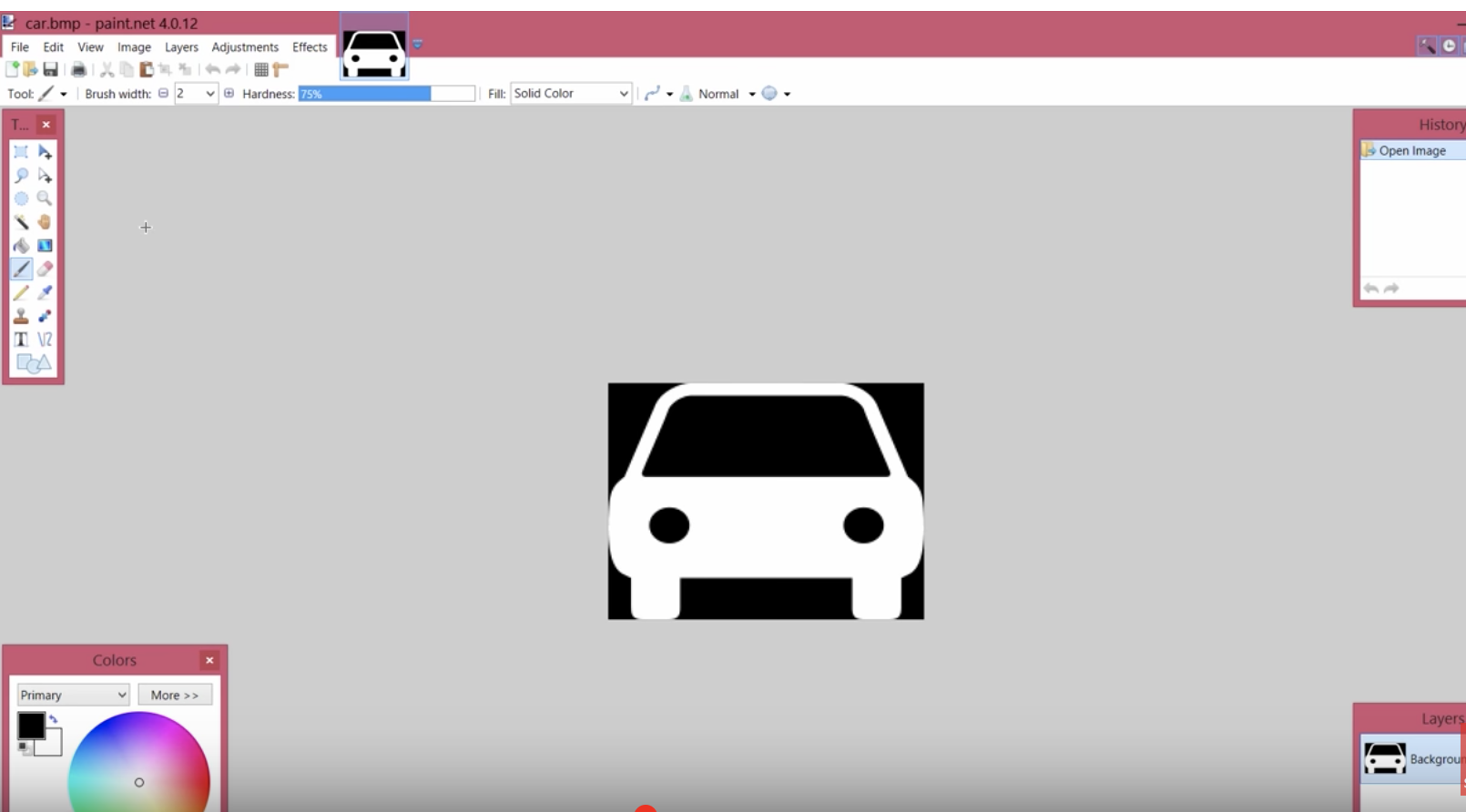
Before an image is displayed on any of the Arduino screens, it needs to be converted to a C compatible hex file and that can only happen when the image is in bitmap form. Thus, our first task is to create a bitmap version of the graphics to be displayed or convert the existing image to a bitmap file. There are several tools that can be used for creation/conversion of bitmap images including, Corel Draw and Paint.net, but for this tutorial, we will use the Paint.net.
Our demo graphics today will be a car. We will create the car on a black background and use a white fill so it’s easy for us to change the color later on.
Using Paint.Net
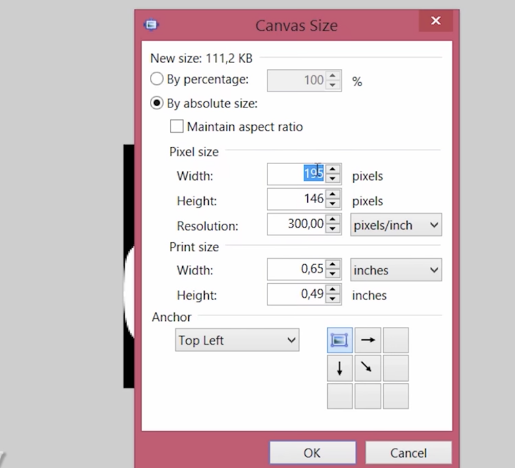
The resolution of the graphics created should be smaller than the resolution of your display to ensure the graphics fit properly on the display. For this example, the resolution of the display is 320 x 340, thus the resolution of the graphics was set to 195 x 146 pixels.
Set the Resolution to Match Your Display
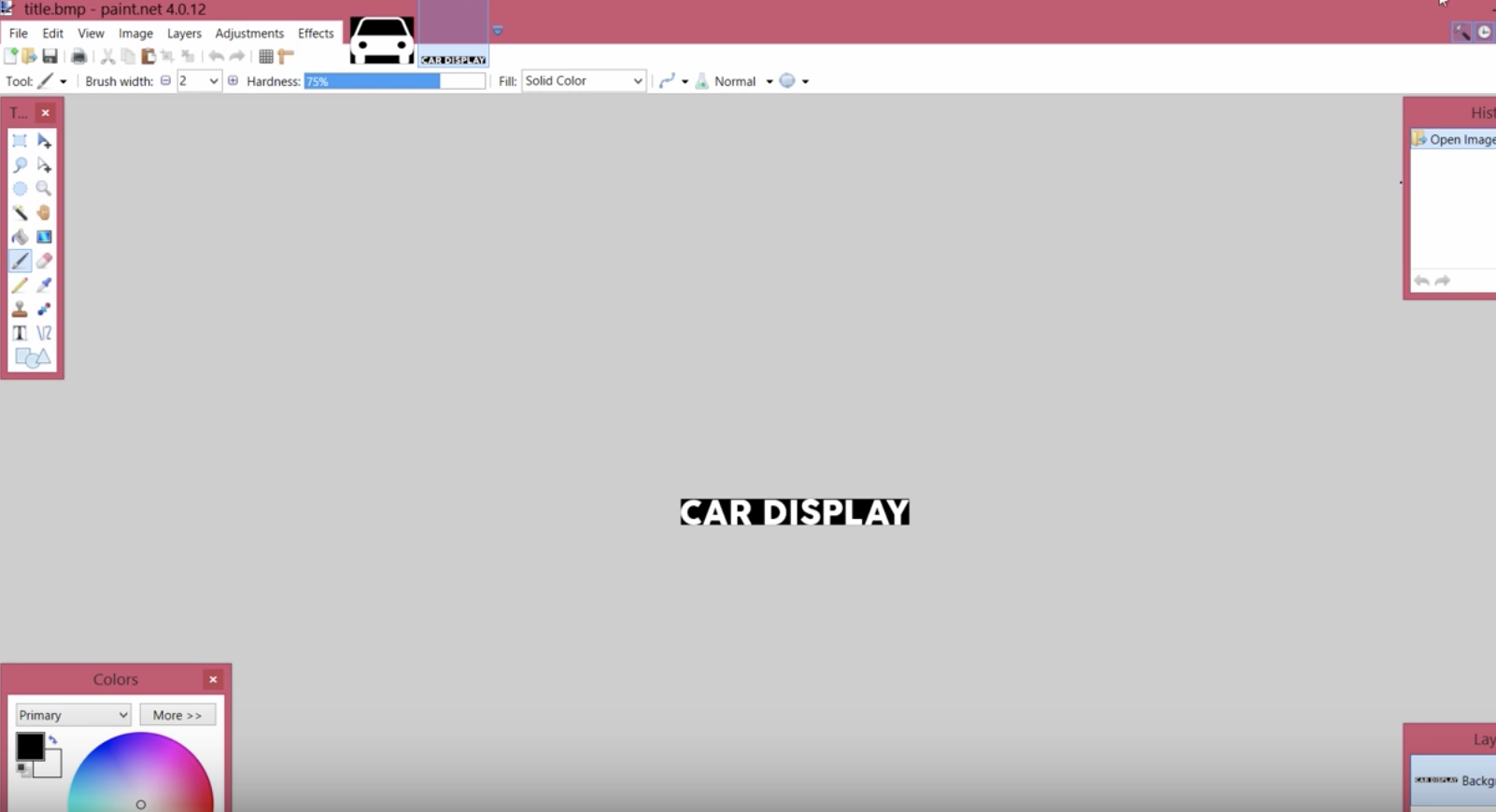
Your graphics could also include some text. Just ensure the background is black and the fill color is white if you plan to change the color within your Arduino code.
Displaying graphical Text
With the graphics done, save both files as .bmp with 24bits color. It is important to keep in mind that large bitmaps use up a lot of memory and may prevent your code from running properly so always keep the bitmaps as small as possible.
The next task is to convert the graphics into byte arrays so they can be used in the code.
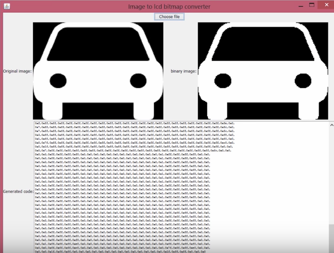
Image2Code is an easy-to-use, small Java utility to convert images into a byte array that can be used as a bitmap on displays that are compatible with the Adafruit-GFX or Adafruit TFTLCD (with little modification) library.
All we have to do is to load the graphics into the software by clicking the “Choose file” button and it will automatically generate a byte array equivalent to the selected bitmap file.
Conversion from Image to Data
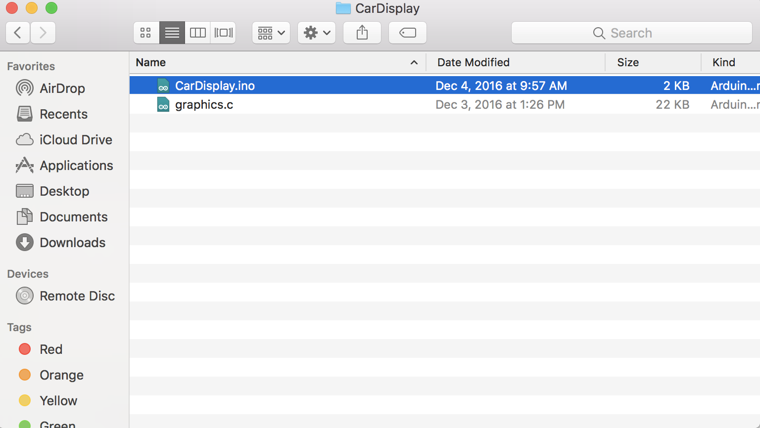
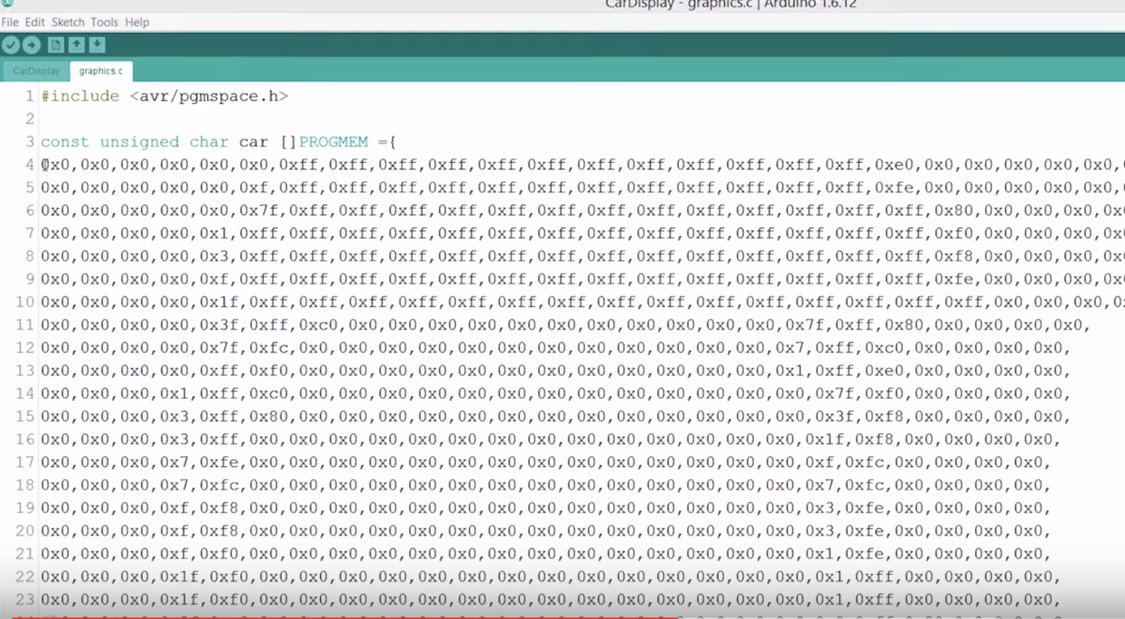
Copy the generated bit array, and create a graphics.c file in the same Arduino project folder where the code will reside.
Ensure the File is in the Same Directory as your main code
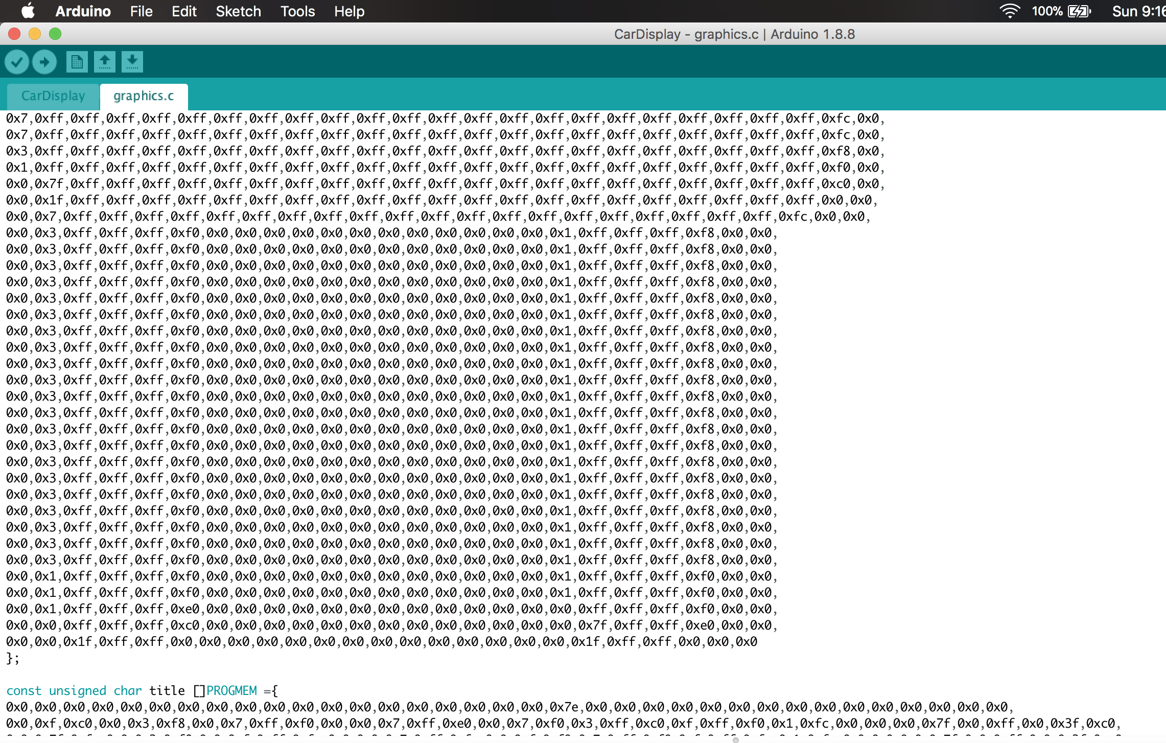
Paste the bit array in the graphics.c file and save. Since we have two graphics (the car and the text), You can paste their data array in the same file. check the graphics.c file attached to the zip file, under the download section to understand how to do this. Don’t forget to declare the data type as “const unsigned char“, add PROGEM in front of it and include the avr/pgmspace.h header file as shown in the image below. This instructs the code to store the graphics data in the program memory of the Arduino.
Copying the Hex file to the Arduino IDE
With this done, we are now ready to write the code. Do note that this procedure is the same for all kind of displays and all kind of graphics. Convert the graphics to a bitmap file and use the Img2code utility to convert it into a hex file which can then be used in your Arduino code.
Code
To reduce the amount of code, and stress involved in displaying the graphics, we will use two wonderful libraries; The GFX library and the TFTLCD library from Adafruit.
The GFX library, among several other useful functions, has a function called drawBitmap(), which enables the display of a monochrome bitmap image on the display. This function allows the upload of monochrome only (single color) graphics, but this can be overcome by changing the color of the bitmap using some code.
The Adafruit libraries do not support all of the displays but there are several modifications of the libraries on the internet for more displays. If you are unable to find a modified version of the library suitable for your the display, all you need do is copy the code of the drawBitmap() function from the GFX library and paste it in the Arduino sketch for your project such that it becomes a user-defined function.
The drawBitmap function takes 6 arguments as shown in the code snippet below;
The first two are the x and y coordinates of a point on the screen where we want the image to be displayed. The next argument is the array in which the bitmap is loaded in our code, in this case, it will be the name of the car and the text array located in the graphics.c file. The next two arguments are the width and height of the bitmap in pixels, in other words, the resolution of the image. The last argument is the color of the bitmap, we can use any color we like. The bitmap data must be located in program memory since Arduino has a limited amount of RAM memory available.
Since using a display without the GFX library is more complex, it’s probably better to do an explanation of how to write the code for this procedure.
As usual, we start writing the sketch by including the libraries required. For this procedure, we will use the TFTLCD library alone, since we are assuming you are using a display that is not supported by the GFX library.
Next, we create the colors to be used, specifying the matching hex values and then create an instance of the TFTLCD library.
#define BLACK   0x0000
#define BLUE    0x001F
#define RED     0xF800
#define GREEN   0x07E0
#define CYAN    0x07FF
#define MAGENTA 0xF81F
#define YELLOW  0xFFE0
#define WHITE   0xFFFF
#define GREY     0xD6BA

Adafruit_TFTLCD tft(LCD_CS, LCD_CD, LCD_WR, LCD_RD, LCD_RESET);
Next, we specify the name of the graphics to be displayed; car and title. At this stage, you should have added the bit array for these two bitmaps in the graphics.c file and the file should be placed in the same folder as the Arduino sketch.
extern uint8_t car[];
extern uint8_t title[];
Next, we write the void setup function. All we do here is to initialize the screen and rotate it to a preferred orientation.
With that done, we proceed to the void loop function, under the loop function, we call the drawbitmap() function to display the car and the text bitmap using different colors.
The last section of the code is the drawBitmap function itself, as earlier mentioned, to use the drawbitmap() function with the Adafruit TFTLCD library, we need to copy the function’s code and paste into the Arduino sketch.
Plug in your screen as shown above. If you are using any other display, connect it as shown in the corresponding linked tutorial. With the schematics in place, connect the Arduino board to your PC and upload the code. Don’t forget the graphics file needs to be in the same folder as the Arduino sketch.
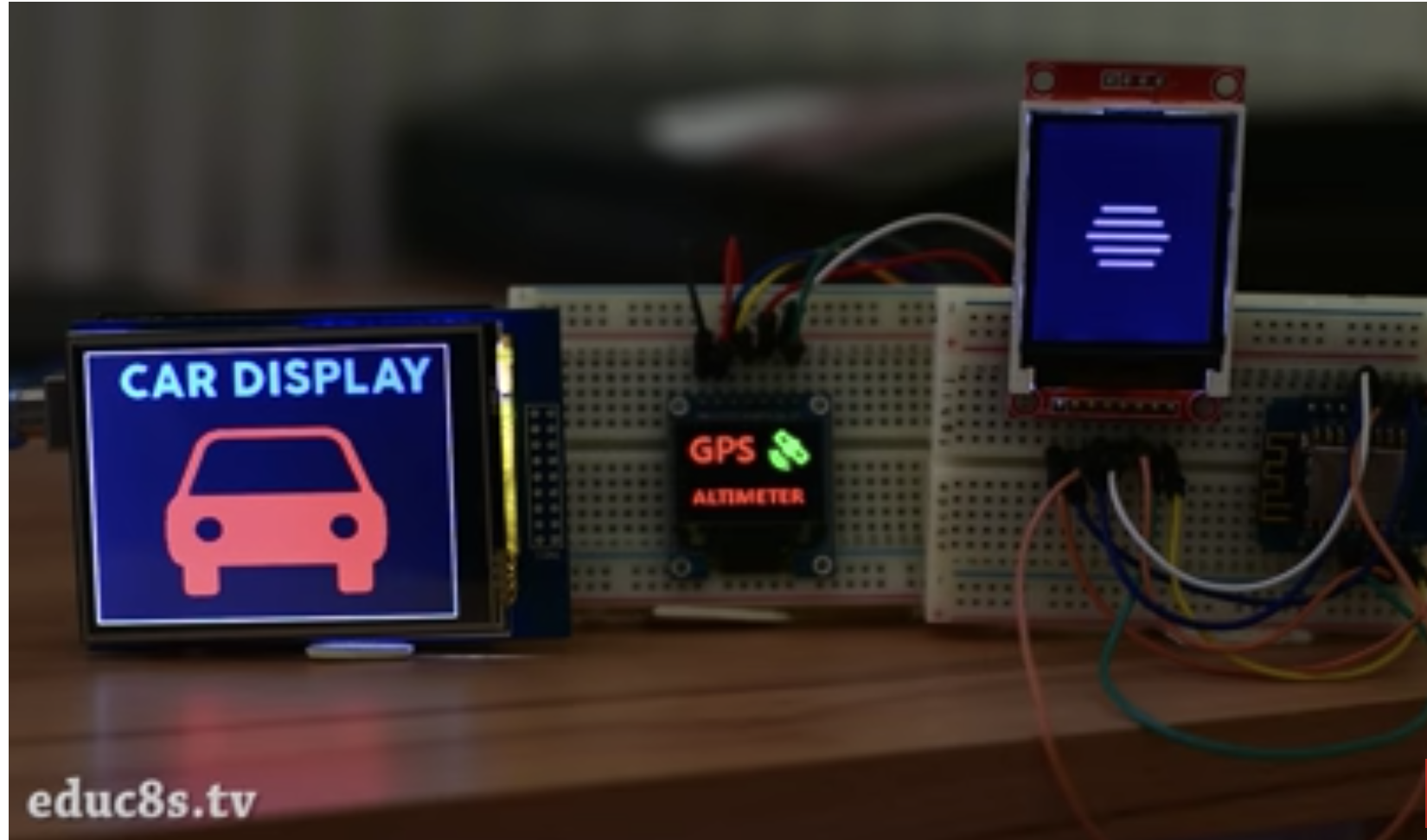
With that done, you should see your screen come up as shown in the image below.
Demo
That’s it for this tutorial guys. The procedure is the same for all kinds of Arduino compatible displays. If you get stuck while trying to replicate this using any other display, feel free to reach out to me via the comment sections below.
Till Next time.
The video version of this tutorial is available on Youtube.
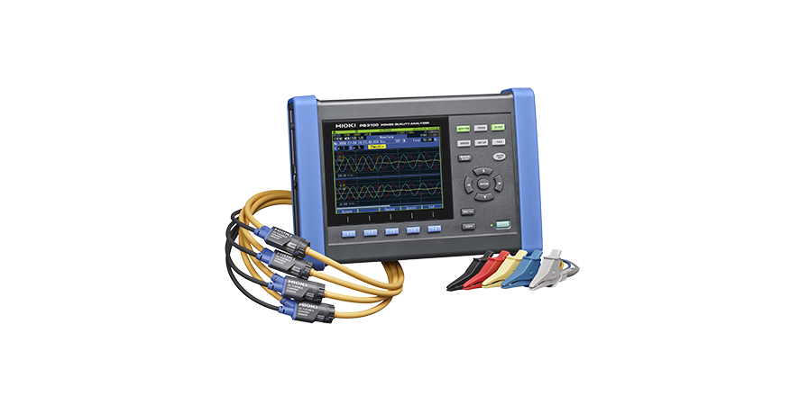
The Hioki PQ3198 portable power analyzer is a best in class power measuring instrument for single to three-phase lines, offering a high degree of precision and accuracy. Verify power problems in accordance with IEC61000-4-30 Class A.
Saelig Company, Inc. has introduced the Hioki PQ3198 Power Quality Analyzer, which can conveniently be used for assessing power usage as well as for investigating power supply problems such as voltage drops, flicker, harmonics, and other electrical issues, so that their causes to be quickly investigated. Hioki portable power analyzers can measure single to three-phase lines with a high degree of precision and accuracy. New features include the ability to drive current sensors straight from the analyzer with enhanced recording capabilities.
The PQ3198 analyzer can be used for single-phase2-wire or 3-wire, three-phase 3-wire or 4-wire plus one extra input channel for voltage, current, power measurement (AC or DC). Sampling at 2MHz, voltages up to 600Vrms (transients to 6kV peak) and currents from 500mA to 5kA can be accommodated, depending on the selected sensor. Comprehensive power analysis of multiple parameters can be made in accordance with the IEC61000-4-30 Class A standard with high accuracy and continuous gapless recording. Voltage dips, swell, inrush, transients to 0.5us, flicker, harmonics, distortion, K factor, etc. can all be analyzed and displayed via the 6.5” TFT LCD. The broadband voltage range allows high-order harmonic component measurements up to 80kHz. In addition to 50/60Hz, the PQ3198 can measure a line 400Hz frequency. An optional battery pack allows continuous isolated use for up to 180 minutes.
The Hioki PQ3198 Power Quality Analyzer simplifies the analysis of power problems: fluctuations in voltage, current, power, harmonics, and flicker when, for instance, connecting a highly variable system such as a renewable energy source or EV charging station to the grid. The data can be further analyzed with the included PQ ONE PC software. The GPS Option PW9005 can be used to synchronize the instrument’s internal time to UTC standard time. This capability eliminates any time difference between multiple instruments.
The Hioki PQ3198 Power Quality Analyzer provides critical robust support for field personnel who need to analyze power characteristics, reliably capturing a full range of power anomalies with an exceptional ease of use. Applications include verifying the power quality of EV rapid chargers, detecting intermittent or poor quality power feeds, assessing light flicker issues, testing for abnormal waveforms when switching to UPS power, solar power quality surveys, etc.
Designed and manufactured by Japan-based Hioki, a world-renowned developer and manufacturer of innovative test and measurement instruments, the PQ3198 Power Quality Analyzer is available now from Saelig Company, Inc. their USA technical distributor.
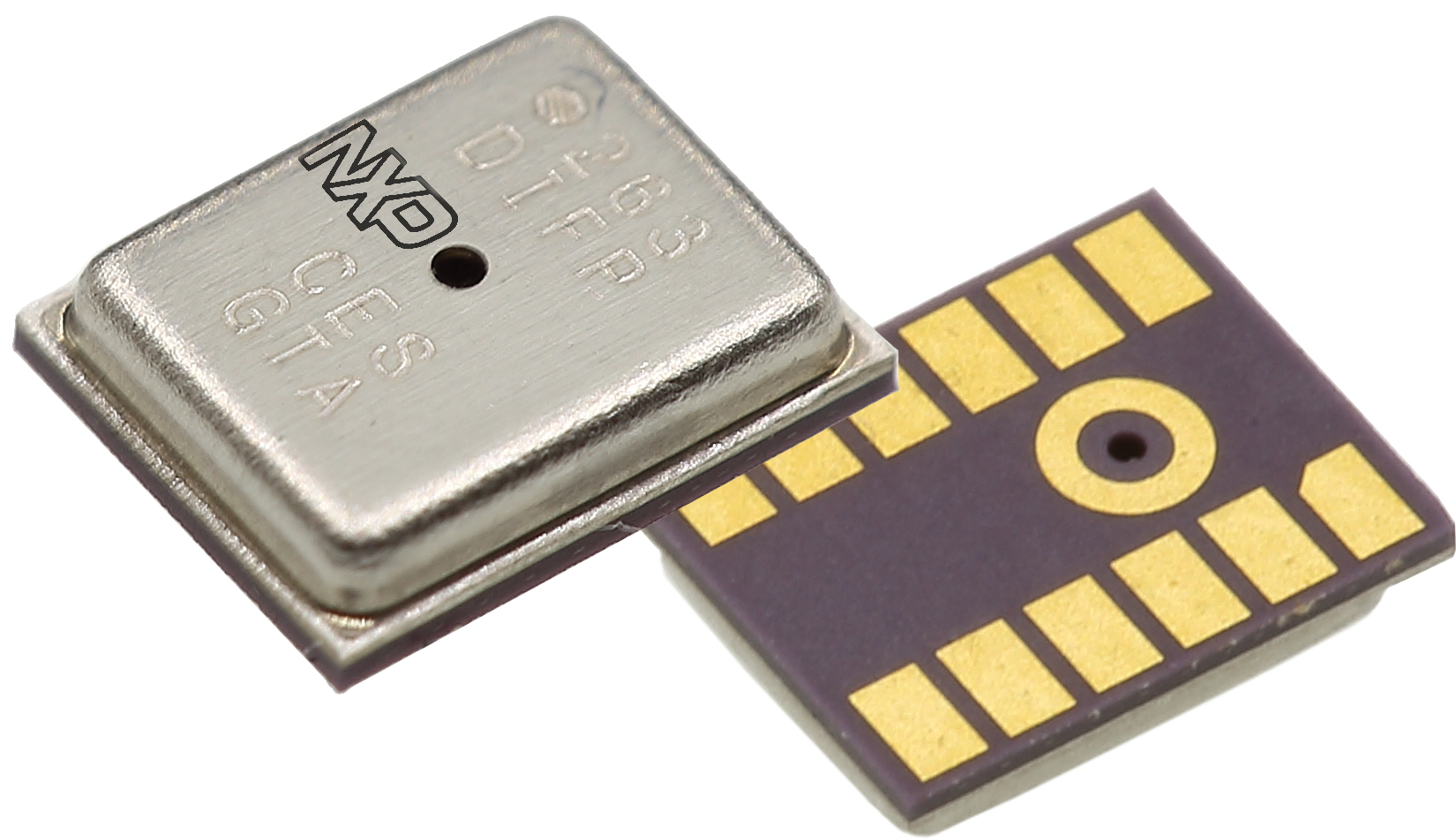
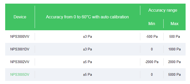
NPS30xx is the last NXP family of digital differential pressure sensor in a tiny 4x5mm LGA package with ceramic lead frame.
This complete family offers low pressure measurement (NPS3000VV = +/500Kpa, NPS3001DV = 0/1Kpa, NPS3002VV = +/-2Kpa, NPS3005DV = 0/5Kpa) combined with absolute accuracy down to 3Pa. It also offers an ultra-low power consumption down to 3.1uA in a measurement mode.
On top of using the serial SPI or I²C interface, user can also benefit from embedded interrupts to trigger wake up based on various configuration of pressure and/or temperature change – and therefore significantly reduce system power.
This family is targeting 2 different markets :
Heating, Ventilation and Air conditioning market, used as flow sensor when combined with a Venturi element or simple obstruction made by a filter or a fan. The very good offset stability and high accuracy are key parameters here. More specifically, wireless smart filter with a BLE connectivity is a new application that can be targeted thanks the low power capability
Medical market for e-inhaler, drug delivery and CPAP machine. The NPS30xx pressure sensor piezo resistive element is actually protected by a bio-compatible gel coating that will facilitate medical certification. Again interrupt capabilities and low power performance together with very small form factor are the key criteria’s here.
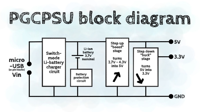
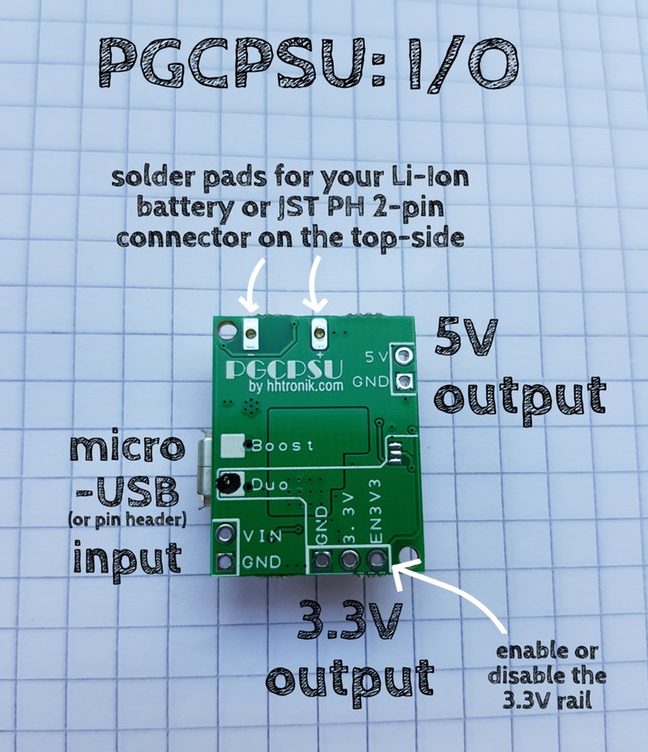
Pretty Good Cheap Power Supply Unit – PGCPSU. Get the best tiny power supply for your battery powered projects!
PGCPSU is a three in one power supply board: it integrates a lithium battery charge management circuit with 5V and 3.3V DC-DC converter-based output rails to power most projects in a very compact form factor. We took special care in selecting inexpensive yet well-fitting parts to make up for a great little power(ful) supply!
Features
Power Input – micro USB input or pin header for charging (4.7V to 6V max.)
Power Output
5V rail providing at least 350mA, and up to 650mA
3.3V rail providing at least 400mA, and up to 800mA
Safety
Integrated battery protection including reverse polarity protection
Over-discharge, short circuit/over-current protection
Power Efficiency
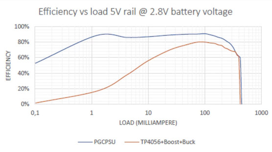
High efficiency even at low load, important for long battery life
Low quiescent current (49uA for the 5V rail + 57uA for the 3.3V rail)
Enable/disable pin for the 3.3V rail with selectable default state solder jumper
Charging – Quick charging at up to 1.9A (fully charges a 2,600mAh cell in about 2 hours)
Dimensions – 25x20mm
The module can also be used as an uninterruptible power supply.
PGCPSU is live on Kickstarter with a €1,250 funding target. Rewards start at 7 Euros for a PGCPSU DUO (5V/3.3V) module and a PGCPSU Boost (5V only) module, but once all early bird rewards are gone price for PGCPSU Duo is offered for 11 Euros, or you may consider a starter kit with a DUO module plus a 2,600 mAh 18650 LiPo battery. Shipping adds a further 7 Euros, and backers can expect their rewards between May and August 2019 depending on the selected perk.
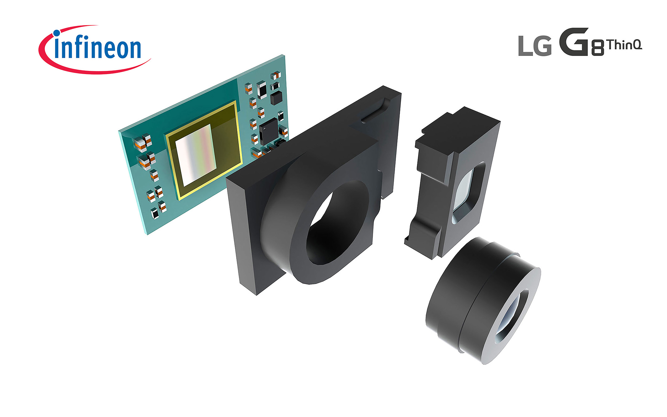
With Infineon’s REAL3™ Image Sensor Chip, LG Offers Enhanced Security and Depth Measuring Selfie Camera
LG Electronics and Infineon Technologies AG have teamed up to introduce leading edge Time-of-Flight (ToF) technology to smartphone selfie photo lovers world over.
Infineon’s REAL3™ image sensor chip will play a key role in the front-facing camera of the upcoming LG G8 ThinQ, to be unveiled in Barcelona during Mobile World Congress 2019. Building upon the combined expertise of Infineon and pmdtechnologies in algorithms for processed 3D point clouds (a set of data points in space produced by 3D scanning), the innovative sensor will deliver a new level of front camera capability in a smartphone.
While other 3D technologies utilize complex algorithms to calculate an object’s distance from the camera lens, the ToF image sensor chip delivers more accurate measurements by capturing infrared light as it is reflected off the subject. As a result, ToF is faster and more effective in ambient light, reducing the workload on the application processor thereby also reducing power consumption.
And due to its fast response speed, ToF technology is widely used in various biometric authentication methods, such as face-recognition. What’s more, because ToF sees objects in 3D and is not affected by light from external sources, it delivers an excellent recognition rate, both indoors and out, ideal for implementation in augmented reality (AR) and virtual reality (VR) applications.
The world’s leading manufacturer of power semiconductors, Infineon is also recognized for its technological excellence in sensor solutions. The German chip maker enables highly reliable automotive, power management and digital security applications. The company developed the ToF technology featured in the LG G8 ThinQ for use in both premium, high-end smartphones as well as mid-end devices.
Infineon is poised to revolutionize the market, said Andreas Urschitz, division president of Infineon’s Power Management & Multimarket division.
We have demonstrated service beyond the mere product level – specifically catering to phone OEMs, associated reference design houses and camera module manufacturers. Within five years, we expect 3D cameras to be found in most smartphones and Infineon will contribute a significant share.
Keeping in mind LG’s goal to provide real value to its mobile customers, our newest flagship was designed with ToF technology from inception to give users a unique and secure verification system without sacrificing camera capabilities,
said Chang Ma, senior vice president and head of Product Strategy at LG Mobile Communications Company.
The LG G8 ThinQ featuring ToF will be the optimal choice for users in search of a premium smartphone that offers unmatched camera capabilities.
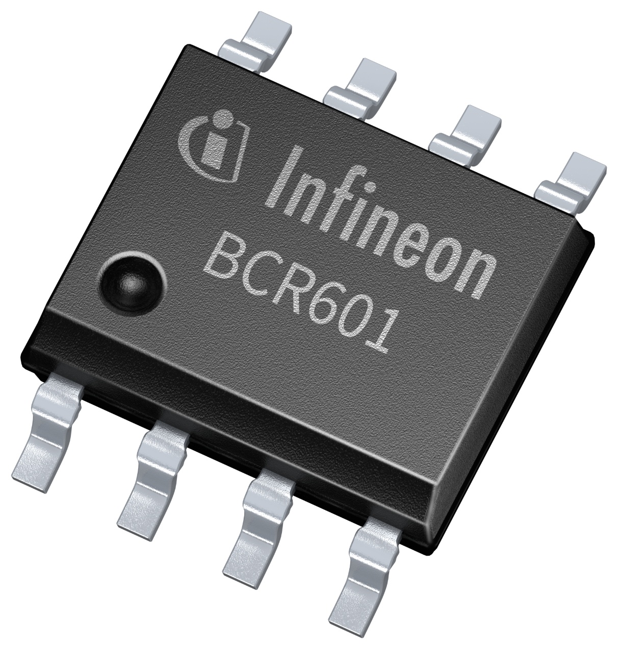
Two linear LED controller ICs have been added to the BCR portfolio, by Infineon Technologies. The BCR601 has voltage feedback to the primary side (also known as active headroom control or AHC), for cost effective and power efficiency LED driver applications.
The BCR602 targets dimmable LED applications such as light engines, modules and strips. It has a wide voltage range of up to 60V makes it suitable for 48V designs and DC/DC grids, confirms Infineon.
The supply voltage of both LED controller ICs ranges from 8.0 to 60V up to the SELV limit. Both the BCR601 and BCR602, operate with an external driver transistor, either an NPN bipolar transistors or an N-channel MOSFET to support a wide LED current and power range.
The ICs allow the LED current to be adjusted by resistors as well as dimmed analogue. The BCR602 also accepts digital PWM up to 3.5 kHz and combined dimming.
Both the BCR601 and BCR602 represent an inherent AC ripple suppression, driving a constantly stable LED current to prevent light flicker.
The AHC of the BCR601 allows controlling the output voltage of the primary side converter such as the XDPL8218 flyback controller from Infineon. This architecture helps a linear LED controller to achieve maximum system efficiency by actively adjusting the AC/DC feedback loop to set minimum voltage headroom.
Adjusting the minimum necessary voltage across the pass transistor optimises system efficiency which can normally only be achieved by secondary switched mode device, points out Infineon, to reduce component temperatures and stress. This construction also reduces EMI compared to switched mode supplies in combination with a low bill of materials, adds Infineon. Additionally, the BCR601 features an adjustable over-voltage protection to prevent any damage to the LEDs.
Both ICs also offer embedded hot-plug protection. This allows connecting or disconnecting the LED load without power down protecting the LEDs from electrical over-stress events. The over-temperature protection reduces the LED current by 30 per cent of the nominal current as soon as the junction temperature exceeds the defined threshold. The LED controller ICs resume regular operation as soon as the temperature drops below the hysteresis.
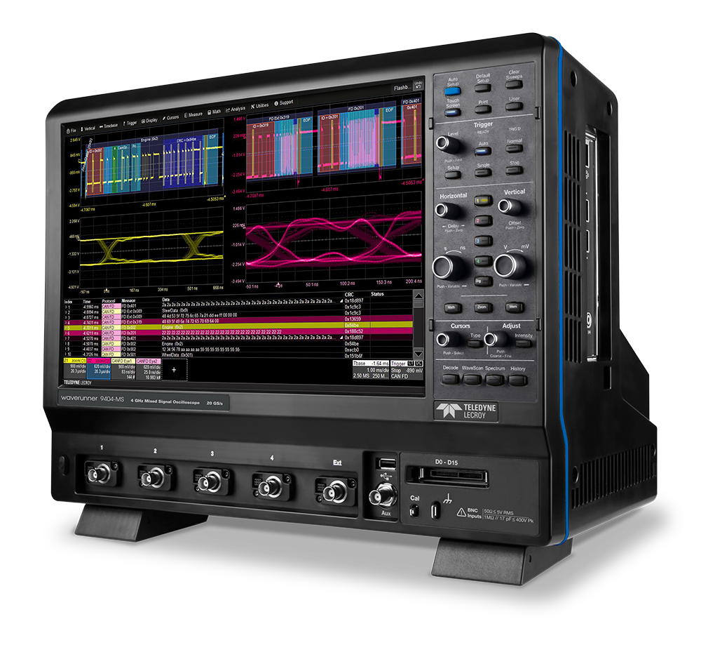
Teledyne LeCroy today introduced its WaveRunner 9000 Series mixed-signal oscilloscopes with a large, 15.4” display, bandwidths from 500 MHz to 4 GHz, and sample rates up to 40 GS/s. The WaveRunner 9000 Series offers the industry’s deepest toolbox and the most complete collection of serial data debug and validation solutions, making it ideal for embedded system, automotive, and EMC/EMI test applications.
The ubiquity of embedded computing systems with high-speed microprocessors drives industry demand for mid-range, mixed-signal oscilloscopes with high bandwidth and powerful debug and validation toolsets. However, equipment budgets have not kept pace with the increase in microprocessor speed and complexity. This has forced engineers and managers to sacrifice certain capabilities in their test equipment. Teledyne LeCroy’s WaveRunner 9000 oscilloscopes offers all of the critical features—a large display, powerful toolbox, wide range of bandwidths, and enhanced resolution up to 11 bits—at an affordable price.
The WaveRunner 9000 Series offers the industry’s deepest toolbox with a large 15.4” display at a price point that does not require engineers to sacrifice features or performance,” said Tyler Cox, VP and general manager for oscilloscopes/digitizers. “The vast serial data coverage of these new oscilloscopes makes them perfect for embedded/automotive testing, and the 40 GS/s sampling rate is ideal for EMI/EMC testing.
About the WaveRunner 9000
The WaveRunner 9000 offers a huge array of test, debug, and validation tools, making it well suited for comprehensive testing of embedded computing systems. The widest selection of serial data triggering and decode (TD) packages provides powerful, flexible serial triggering with an intuitive color-coded decode overlay. Additionally, unique measure/graph and eye-diagram test (TDME) packages complement the TD packages by enabling extraction of decoded data and subsequent waveform data plots, performing bus timing measurements, and creating eye diagrams for testing against standard or custom masks. This set of tools provides exhaustive causal analysis for not only embedded systems but also automotive applications, covering all aspects of Automotive Ethernet validation and debug, including 1000Base-T1 and 100Base-T1 compliance test.
WaveRunner 9000 oscilloscopes have standard capability to provide improved resolution with bandwidth tradeoffs by means of filtering, and each channel can be filtered independently. The filtered result shows the improvement in the number of effective bits at a given bandwidth.
For EMC/EMI compatibility applications, WaveRunner 9000 accurately characterizes EMC test signals with a 40 GS/s sampling rate and 1% gain accuracy. The WaveRunner 9000’s spectral analysis mode pins down high harmonic peaks across a wide EMC band using an interactive peaks and markers table. In addition, a dedicated EMC pulse parameter measurement package enables the user to tailor measurements to specific EMC/ESD standards.
Price and Availability
The WaveRunner 9000 oscilloscopes start at $16,435 and are available now. An extensive range of probes is optionally available to serve virtually any probing requirement.
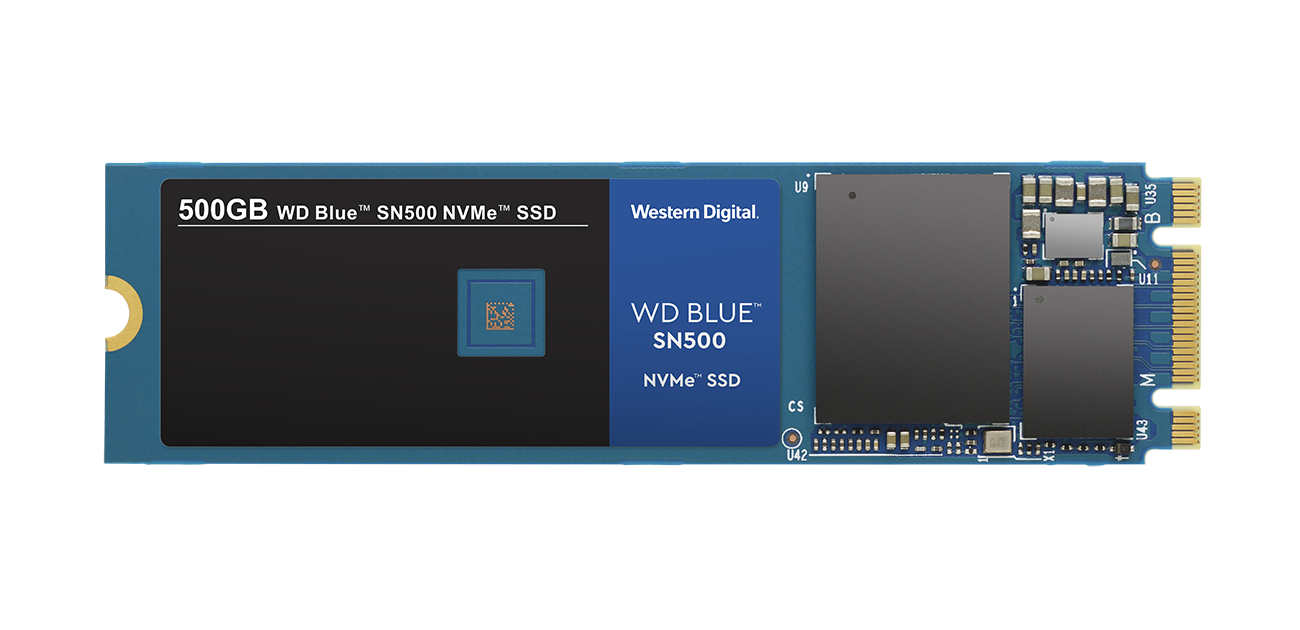
Western Digital Corp. , a global data infrastructure leader, is accelerating the NVMe transition of value-PC storage by adding an NVMe™ model to its award-winning WD Blue® solid state drive (SSD) portfolio, the WD Blue SN500 NVMe SSD. The new SSD delivers three-times the performance of its SATA counterpart1 while maintaining the reliability the WD Blue product line is known for. For content creators and PC enthusiasts, the WD Blue SN500 NVMe SSD is optimized for multitasking and resource-heavy applications, providing near-instant access to files and programs.
Leveraging the scalable in-house SSD architecture of the highly acclaimed WD Black® SN750 NVMe SSD, the new WD Blue SN500 NVMe SSD is also built on Western Digital’s own 3D NAND technology, firmware and controller, and delivers sequential read and write speeds up to 1,700MB/s and 1,450MB/s respectively (for 500GB model) with efficient power consumption as low as 2.7W.* Since demands on storage are continuing to grow and client workloads are evolving, the WD Blue SN500 NVMe SSD features high sustained write performance over SATA as well as other emerging technologies on the market today to give that performance edge.
The PC industry continues its transition from SATA to the NVMe protocol, along with the expectation from consumers that computers continue to become faster and more responsive, said Don Jeanette, TrendFocus.
Within the mainstream segment, content creators are consistently doing more, such as editing 4K or 8K video files, creating and streaming content, and managing massive amounts of data internally. The new WD Blue SN500 NVMe SSD will enable larger file loads that require faster storage.
Content transitioning from 4K and 8K means it’s a perfect time for video and photo editors, content creators, heavy data users, and PC enthusiasts to transition from SATA to NVMe, said Eyal Bek, vice president marketing, data center and client computing, Western Digital.
The WD Blue SN500 NVMe SSD will enable customers to build high-performance laptops and PCs with fast speeds and enough capacity in a reliable, rugged and slim form factor.
Perfect in slim form factor notebooks or desktop PCs, the WD Blue SN500 NVMe SSD will be available in 250GB and 500GB capacities in a single-sided M.2 2280 PCIe Gen3 x2 form factor. Manufacturer’s Suggested Retail Price (MSRP) in the U.S. is $54.99 USD for 250GB (model number: WDS250G1B0C) and $77.99 USD for 500GB (model number: WDS500G1B0C). For more information, visit the website: Western Digital.
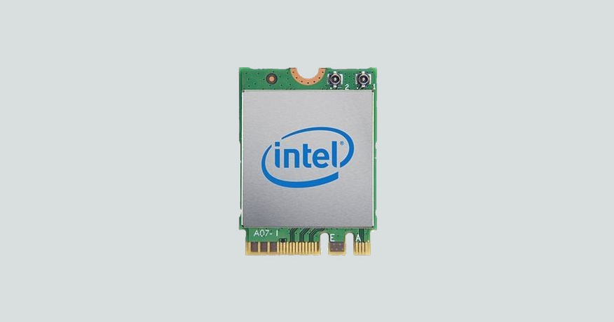
WiFi 6 (aka 802.11ax) can deliver up to 10 Gbps in theory, and provides better handling of high density scenario in train stations, conferences, etc… We’ve seen it implemented in some routers and smartphones, but most laptops don’t support the new WiFi standard, so in order to solve this little issue, Intel has now launched AX200 M.2 WiFi 6 card in the M.2 2230 and M.2 1216 form-factors.
The AX200 uses an M.2 2230 form factor, supports a max speed of 2.4Gbps, and supports Bluetooth 5. The AX200 parts will be available at $10 to $17 USD.
Drivers are/will be available for Windows 10 64-bit, Google Chrome OS, and Linux via the “IWLWIFI” driver.