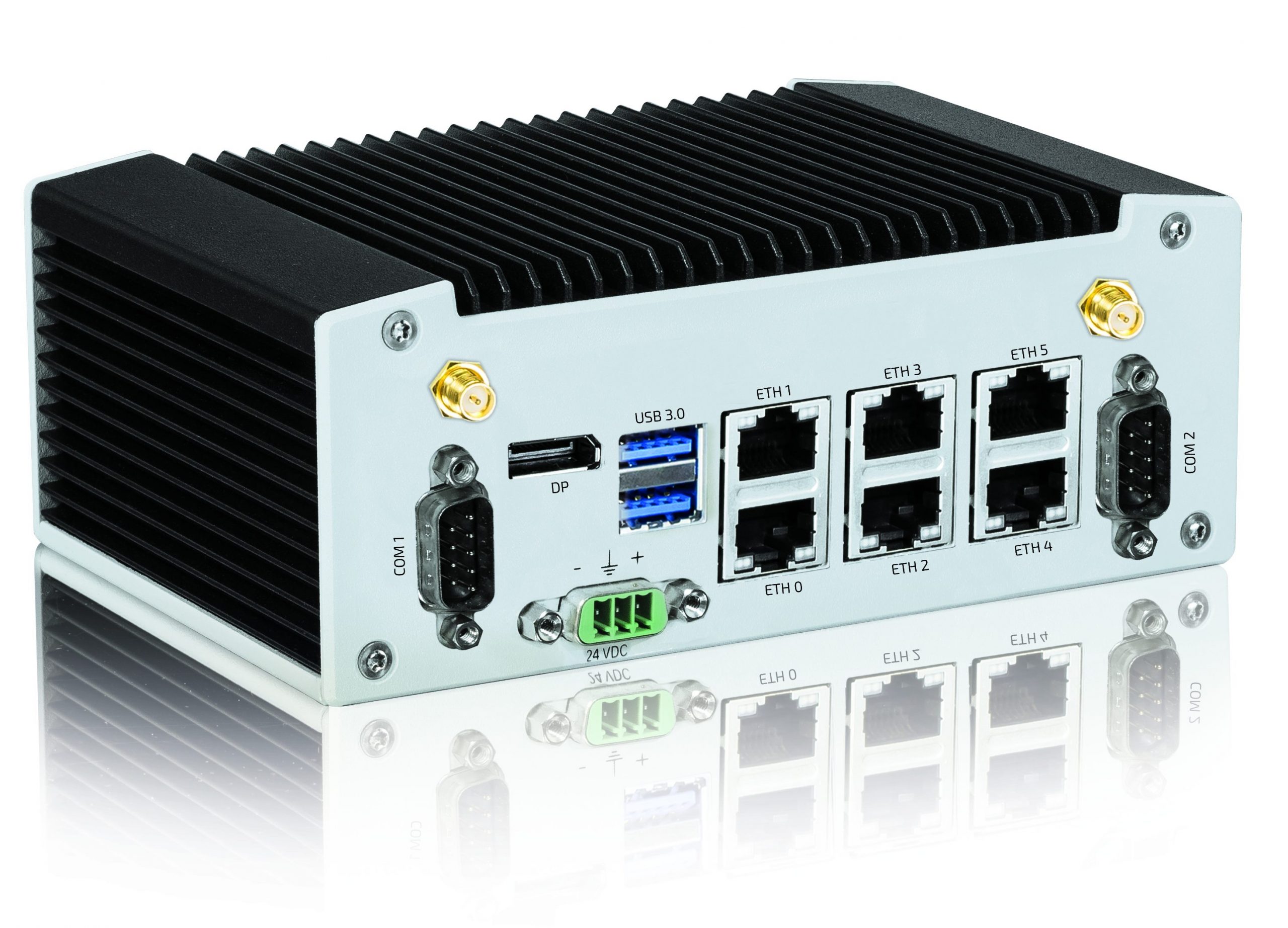
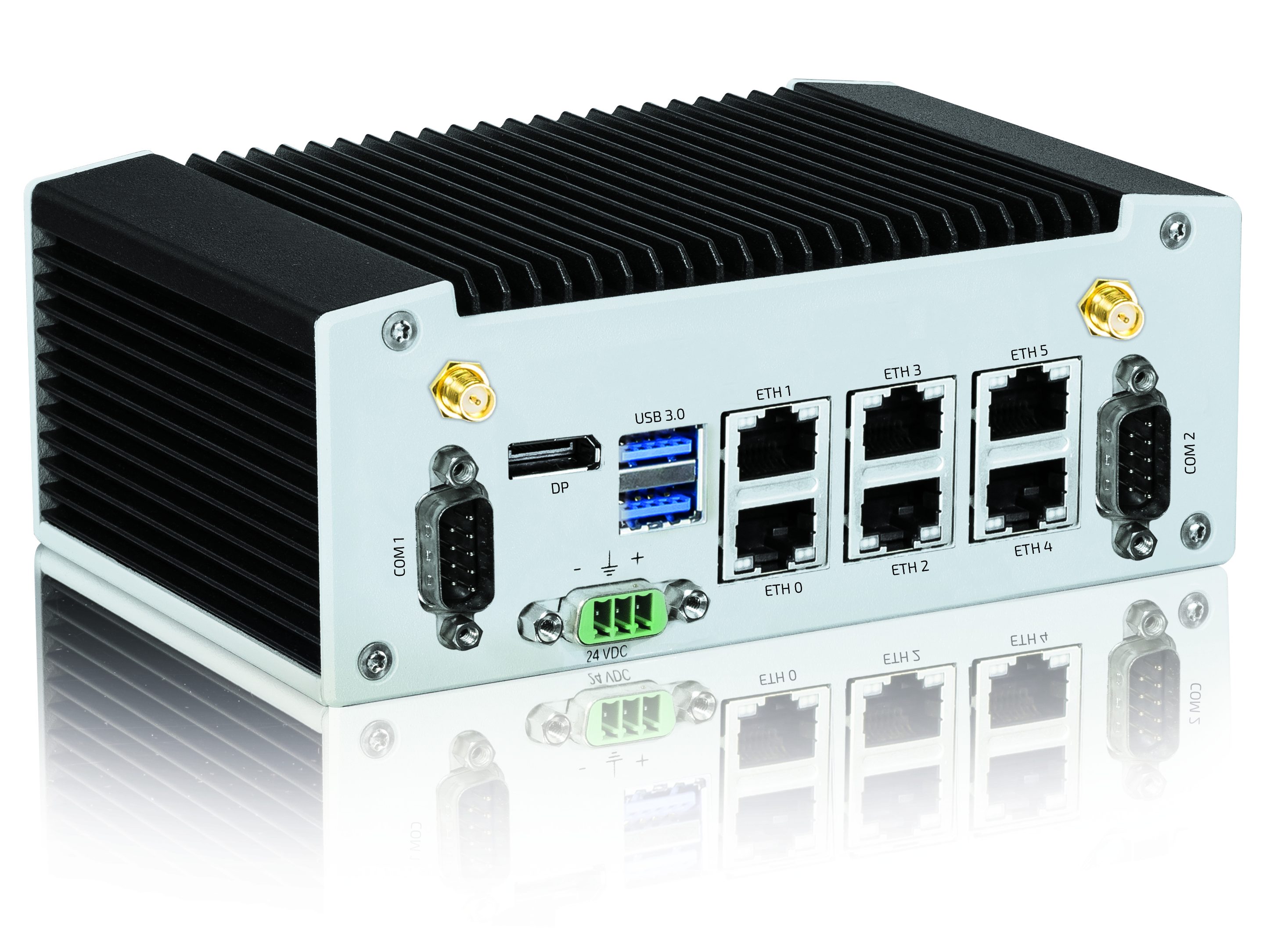
KBox A-230-LS with SMARC-sAL28 offers up to five TSN-enabled 1GB Ethernet ports for IoT applications
Kontron, a leading global provider of IoT/Embedded Computing Technology (ECT), has announced the KBox A-230-LS, a new compact industrial computer platform designed specifically for Time Sensitive Networking (TSN) applications. The KBox A-230-LS is equipped with a SMARC module based on the NXP Dual Cortex A72 LS1028 processor. The SMARC-sAL28 module offers up to five integrated TSN-enabled 1GB Ethernet ports directly from the controller and fulfills the specifications of the TSN standard IEEE 802.1, making the KBox A-230-LS ideal for use in industrial IoT environments based on Ethernet protocol standards.
The compact, fanless KBox A-230-LS is designed for a variety of industrial applications. The two Arm® v8 processor cores both support real-time processing in industrial control systems and virtual machines for edge computing within the IoT. The CPU includes integrated GPU and LCD controllers, enabling the realization of HMI systems.
The compact KBox A-230-LS offers numerous interfaces that facilitate the connection to different communication levels. A serial interface (RS232/RS485 and optional CAN) enables local data acquisition and connection to the sensor or machine environment. The integration into the IT environment can be achieved via Gigabit Ethernet interfaces. In addition to a regular 1GB Ethernet interface, a total of up to five TSN-capable 1GB Ethernet ports are available. Furthermore, the KBox A-230-LS has a DisplayPort connection, an USB 3.0 and an USB 2.0 interface.
The KBox A-230-LS is equipped with an NXP Dual Cortex A72 LS1028 processor. It supports up to 4GB DDR3L with ECC and has an eMMC onboard flash memory with up to 64GB. Additional storage media are a mSATA SDD, a M.2 SSD or a microSD card. System extensions can be implemented via a MiniPCI Express or M.2 interface.
The KBox A-230-LS is quick and easy to deploy, making it ideal for OEMs and system integrators who want to exploit the full potential of the next generation of intelligent infrastructures in the IoT environment. The KBox A-230-LS is also certified for Microsoft Azure and works ideal with Microsoft Azure IoT Services.
Like all box PCs within the Kontron KBox A-series, the KBox A-230-LS is maintenance-free, as the system is fanless and battery-free. Linux Yocto is used as the operating system. In addition, the KBox A-230-LS optionally supports the Kontron APPROTECT security solution powered by Wibu-Systems. The integrated security chip from Wibu-Systems in combination with a suitable software framework protects IP rights and provides copy and reverse engineering protection. Kontron APPROTECT Licensing also enables new business models such as ‘pay per use’. Moreover, time based trial versions or activating / deactivating functions are offered as well.
Home automation refers to the ability of your home to make its own decisions depending on environment conditions and give you the option to control it from a remote location. In one of our previous tutorial on the ESP8266 WiFi Module, we examined how NodeMCU or any of the other ESP8266 based boards can be used to build a web server through which all the GPIOs of the board can be controlled over WiFi. Today, we are going to put that web server in use and control home appliances with it.
Home Automation using NodeMCU (ESP8266) board – [Link]
Home automation refers to the ability of your home to make its own decisions depending on environment conditions and give you the option to control it from a remote location. In one of our previous tutorial on the ESP8266 WiFi Module, we examined how NodeMCU or any of the other ESP8266 based boards can be used to build a web server through which all the GPIOs of the board can be controlled over WiFi. Today, we are going to put that web server in use and control home appliances with it.
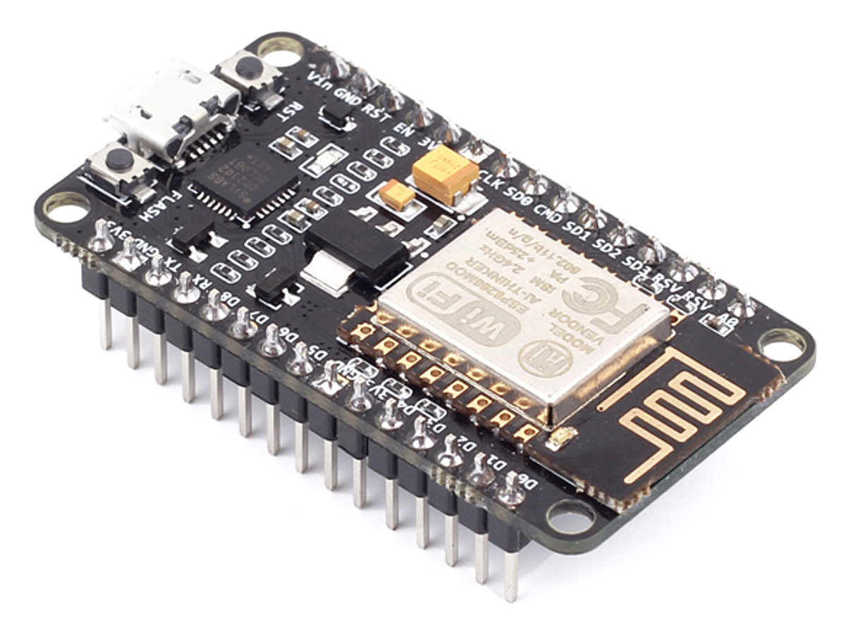
NodeMCU Development Board
The heart of today’s project is the WiFi enabled board that needs no introduction; the ESP8266 based NodeMCUdevelopment board. It is an open source platform for developing WiFi based embedded systems and it is based on the popular ESP8266 WiFi Module, running the Lua based NodeMCU firmware. NodeMCU was born out of the desire to overcome the limitations associated with the first versions of the ESP8266 module which was not compatible with breadboards, it was difficult to power and even more difficult to program. The NodeMCU board is easy to use, low cost and that quickly endeared it to the heart of makers and it is one of the most popular boards today.
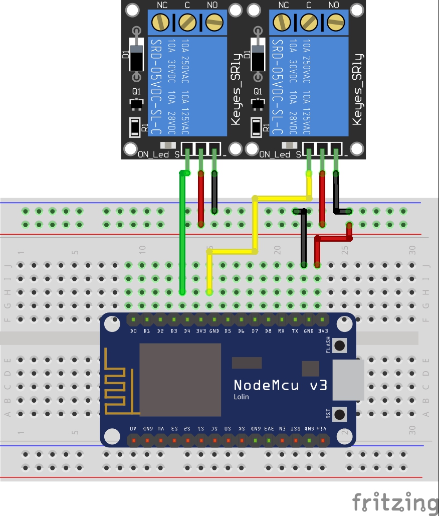
For today’s tutorial, we will add a 2-channel relay module to the ESP8266 board. The project flow involves the control of NodeMCU’s GPIOs from a webpage on any device connected on the same network as the board. The status of the GPIOs control the coils of the relays and that causes the relay to alternate between normally open (NO) and normally closed (NC) condition depending on the state of the GPIO, thus, effectively turning the connected appliance “ON” or “OFF”.
It’s important to note that, connecting the appliances to the relay involves interaction with AC voltages which could be dangerous. Ensure you have experience interacting with AC voltages and do so in a safe manner.
Required Components
The following components are required to build this project:
NodeMCU (ESP8266-12E)
2-Channel Relay Module
Breadboard
Jumper Wire
For those who don’t have access to a relay module, you can use 2x single channel relay modules or single relays with the supporting transistor circuitry. For that purpose you will additionally need:
5v Relays (2)
2N2222 Transistor (2)
1N4007 Diode (2)
220 ohms resistor (2)
5V battery/PSU
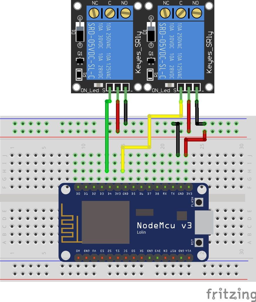
Schematics
The schematics for this project is quite simple. Connect the components as shown in the diagram below.
Schematics
To make the connections easy to follow, here is a pin map of the connection between NodeMCU and the relay module.
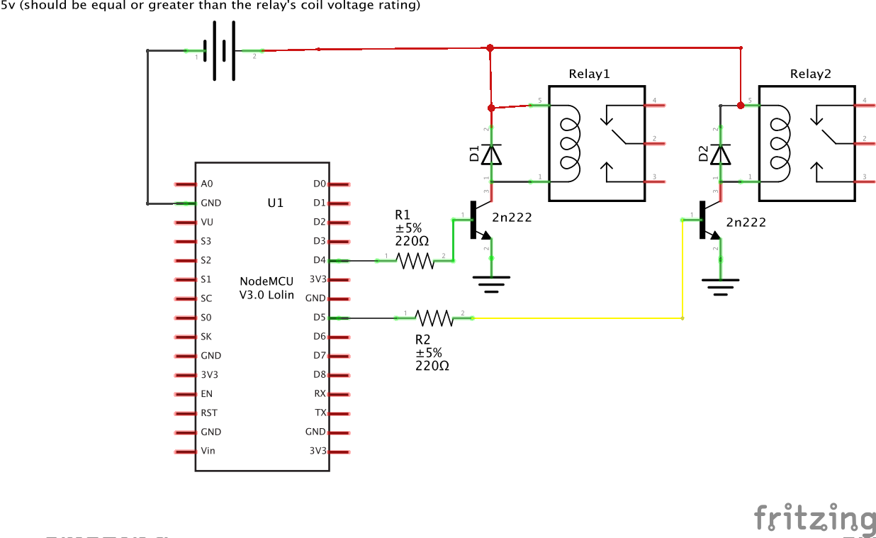
If you are using the ordinary relays without the module supporting circuit, connect the relays to the NodeMCU as shown below. Ensure the relay’s coils are rated 5v or change the 5v supply to match your relay’s rated coil voltage.
Schematics 2
With the schematics done, we can then move forward to write the code for the project.
Code
One of the easiest way to program NodeMCU is via the Arduino IDE. This, however, requires setting up the Arduino IDE by installing the board support file for NodeMCU. If you are using the Arduino IDE to program the NodeMCU for the first time, you need to do this first before proceeding with this tutorial. Follow the detailed tutorial “Getting Started with the NodeMCU” to learn how to set up your Arduino IDE to program ESP8266 based boards.
The code for today’s tutorial is a modified version of the code from the last article “NodeMCU ESP8266 WebServer Tutorial“. The code is based on the ESP8266WiFi.h library which allows the easy use of WiFi functionalities of the board. It contains all we need to create or join a WiFi access point and also create a server and client which are all important for today’s project. The library comes attached with the NodeMCU board files for the Arduino, so there is no need to install it once the board files have been installed.
The code for today’s tutorial will enable us to control appliances connected to the GPIOs (via relays) of the NodeMCU board remotely.
To start with, we include the library that we will use for the project, which in this case, is the ESP8266WiFi.h library.
#include <ESP8266WiFi.h>
Next, we add the credentials of the WiFi access point to which the NodeMCU will be connected. Ensure the username and password are between the double quotes. We also specify the port through which the system will communicate and create a variable to hold requests.
// Add wifi access point credentiaals
const char* ssid     = "xxxxx";
const char* password = "xxxx";

WiFiServer server(80);// Set port to 80
Next, we declare the pins of the Nodemcu to which the relay pins are connected and create variables to hold the state of each relay.
// Declare the pins to which the appliances are connected via relays
int app1 = D1; //appliance 1
int app2 = D2; //appliance 2`
//you can add more more appliances below.

String app1state = "off";// state of appliance1
String app2state = "off";// state of appliance2
Next is the void setup() function. We start by initializing the serial monitor (as it will be used for debugging later on) and setting the pinModes of the pins to which the relays are connected as output. We then set the pins “LOW” to ensure the system starts at OFF state.
void setup() {
  Serial.begin(115200);
 // Set the pinmode of the pins to which the LEDs are connected and turn them low to prevent flunctuations
  pinMode(app1, OUTPUT);
  pinMode(app2, OUTPUT);
  digitalWrite(app1, LOW);
  digitalWrite(app2, LOW);
Next, we connect to the access point using the credentials provided as arguments to the WiFi.begin() function and we use the WiFi.status() function to check if connection was successful. The system will keep trying until the connection is successful.
//connect to access point
  WiFi.begin(ssid, password);
  Serial.print("Connecting to ");
  Serial.println(ssid);
  while (WiFi.status() != WL_CONNECTED) {
    delay(500);
    Serial.print(".");
  }
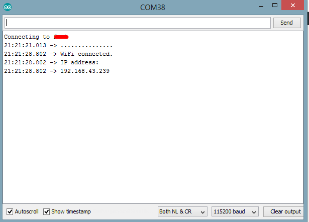
If the connection is successful, a text is printed on the serial monitor to indicate this, along with the IP address of the NodeMCU. This IP address becomes the web address for the server and should be entered on any web browser on the same network as the server so we are able to access it.
// Print local IP address and start web server
  Serial.println("");
  Serial.println("WiFi connected.");
  Serial.println("IP address: ");
  Serial.println(WiFi.localIP());// this will display the Ip address of the Pi which should be entered into your browse
}
Next, we start the server using the server.begin() function.
server.begin();
}
Next, we write the void loop() function. This is where a bulk of the work is done. We start by using the server.available() function to listen for incoming connections by clients (web browsers). When a client is available and connected, we read the client request and send a header as a response.
void loop(){
  WiFiClient client = server.available();   // Listen for incoming clients

  if (client) {                             // If a new client connects,
    String currentLine = "";                // make a String to hold incoming data from the client
    while (client.connected()) {            // loop while the client's connected
      if (client.available()) {             // if there's bytes to read from the client,
        char c = client.read();             // read a byte, then
        Serial.write(c);                    // print it out the serial monitor
        header += c;
        if (c == '\n') {                    // if the byte is a newline character
          // if the current line is blank, you got two newline characters in a row.
          // that's the end of the client HTTP request, so send a response:
          if (currentLine.length() == 0) {
            // HTTP headers always start with a response code (e.g. HTTP/1.1 200 OK)
            // and a content-type so the client knows what's coming, then a blank line:
            client.println("HTTP/1.1 200 OK");
            client.println("Content-type:text/html");
            client.println("Connection: close");
            client.println();
Next, the client’s request is examined to see if it indicates a button press on the web page. If it does, the state of the GPIO is changed accordingly to the request. If the request indicates “ON”, the pin is turned HIGH and the state variable is updated accordingly.
// turns the GPIOs on and off
           if (header.indexOf("GET /app1/on") >= 0) {
             Serial.println("App 1 on");
             app1state = "on";
             digitalWrite(app1, HIGH);
           } else if (header.indexOf("GET /app1/off") >= 0) {
             Serial.println("App 1 off");
             app1state = "off";
             digitalWrite(app1, LOW);
           } else if (header.indexOf("GET /app2/on") >= 0) {
             Serial.println("App 2 on");
             app2state = "on";
             digitalWrite(app2, HIGH);
           } else if (header.indexOf("GET /app2/off") >= 0) {
             Serial.println("App 2 off");
             app2state = "off";
             digitalWrite(app2, LOW);
           }
Next, we create the webpage that will be displayed and updated by the NodeMCU as the user interacts with it. The key function for this is the Client.println() function which is used to send HTML scripts line by line to the client.
We start by indicating that the next few texts to be printed are HTML lines as declaring by doctype.
client.println("<!DOCTYPE html><html>");
Next, we add the lines below to make webpage responsive irrespective of the browser being used.
Next, the webpage header is sent followed by the buttons and the buttons are set to display the current state of the appliances. They will show OFF if the current state is ON and vice versa.
client.println("<body><h1>ESP8266 Web Server</h1>");
// Display current state, and ON/OFF buttons for GPIO 5
client.println("<p>app1 - State " + app1state + "</p>");
// If Appliance 1 is off, it displays the ON button
if (app1state == "off") {
client.println("<p><a href=\"/app1/on\"><button class=\"button\">ON</button></a></p>");
} else {
client.println("<p><a href=\"/app1/off\"><button class=\"button button2\">OFF</button></a></p>");
}
// Display current state, and ON/OFF buttons for GPIO 4
client.println("<p>app2 - State " + app2state + "</p>");
// If Appliance 2 is off, it displays the ON button
if (app2state == "off") {
client.println("<p><a href=\"/app2/on\"><button class=\"button\">ON</button></a></p>");
} else {
client.println("<p><a href=\"/app2/off\"><button class=\"button button2\">OFF</button></a></p>");
}
client.println("</body></html>");
// The HTTP response ends with another blank line
client.println();
// Break out of the while loop
break;
} else { // if you got a newline, then clear currentLine
currentLine = "";
}
} else if (c != '\r') { // if you got anything else but a carriage return character,
currentLine += c; // add it to the end of the currentLine
}
}
}
Next, we close the connection and the flow goes back to the top.
The complete code for the project is available below and also attached under the download section.
#include <ESP8266WiFi.h>
// Add wifi access point credentiaals
const char* ssid = "xxxx";
const char* password = "xxxxx";
WiFiServer server(80);// Set port to 80
String header; // This storees the HTTP request
// Declare the pins to which the appliances are connected via relays
int app1 = D1; //appliance 1
int app2 = D2; //appliance 2`
//you can add more more appliances below.
String app1state = "off";// state of appliance1
String app2state = "off";// state of appliance2
void setup() {
Serial.begin(115200);
// Set the pinmode of the pins to which the LEDs are connected and turn them low to prevent flunctuations
pinMode(app1, OUTPUT);
pinMode(app2, OUTPUT);
digitalWrite(app1, LOW);
digitalWrite(app2, LOW);
//connect to access point
WiFi.begin(ssid, password);
Serial.print("Connecting to ");
Serial.println(ssid);
while (WiFi.status() != WL_CONNECTED) {
delay(500);
Serial.print(".");
}
// Print local IP address and start web server
Serial.println("");
Serial.println("WiFi connected.");
Serial.println("IP address: ");
Serial.println(WiFi.localIP());// this will display the Ip address of the Pi which should be entered into your browser
server.begin();
}
void loop(){
WiFiClient client = server.available(); // Listen for incoming clients
if (client) { // If a new client connects,
String currentLine = ""; // make a String to hold incoming data from the client
while (client.connected()) { // loop while the client's connected
if (client.available()) { // if there's bytes to read from the client,
char c = client.read(); // read a byte, then
Serial.write(c); // print it out the serial monitor
header += c;
if (c == '\n') { // if the byte is a newline character
// if the current line is blank, you got two newline characters in a row.
// that's the end of the client HTTP request, so send a response:
if (currentLine.length() == 0) {
// HTTP headers always start with a response code (e.g. HTTP/1.1 200 OK)
// and a content-type so the client knows what's coming, then a blank line:
client.println("HTTP/1.1 200 OK");
client.println("Content-type:text/html");
client.println("Connection: close");
client.println();
// turns the GPIOs on and off
if (header.indexOf("GET /app1/on") >= 0) {
Serial.println("App 1 on");
app1state = "on";
digitalWrite(app1, HIGH);
} else if (header.indexOf("GET /app1/off") >= 0) {
Serial.println("App 1 off");
app1state = "off";
digitalWrite(app1, LOW);
} else if (header.indexOf("GET /app2/on") >= 0) {
Serial.println("App 2 on");
app2state = "on";
digitalWrite(app2, HIGH);
} else if (header.indexOf("GET /app2/off") >= 0) {
Serial.println("App 2 off");
app2state = "off";
digitalWrite(app2, LOW);
}
// Display the HTML web page
client.println("<!DOCTYPE html><html>");
client.println("<head><meta name=\"viewport\" content=\"width=device-width, initial-scale=1\">");
client.println("<link rel=\"icon\" href=\"data:,\">");
// CSS to style the on/off buttons
// Feel free to change the background-color and font-size attributes to fit your preferences
client.println("<style>html { font-family: Helvetica; display: inline-block; margin: 0px auto; text-align: center;}");
            client.println(".button { background-color: #195B6A; border: none; color: white; padding: 16px 40px;");
            client.println("text-decoration: none; font-size: 30px; margin: 2px; cursor: pointer;}");
            client.println(".button2 {background-color: #77878A;}</style></head>");
// Web Page Heading
client.println("<body><h1>ESP8266 Web Server</h1>");

            // Display current state, and ON/OFF buttons for GPIO 5
            client.println("<p>app1 - State " + app1state + "</p>");
            // If Appliance 1 is off, it displays the ON button
            if (app1state == "off") {
              client.println("<p><a href=\"/app1/on\"><button class=\"button\">ON</button></a></p>");
            } else {
              client.println("<p><a href=\"/app1/off\"><button class=\"button button2\">OFF</button></a></p>");
            }

            // Display current state, and ON/OFF buttons for GPIO 4
            client.println("<p>app2 - State " + app2state + "</p>");
            // If Appliance 2 is off, it displays the ON button
            if (app2state == "off") {
              client.println("<p><a href=\"/app2/on\"><button class=\"button\">ON</button></a></p>");
            } else {
              client.println("<p><a href=\"/app2/off\"><button class=\"button button2\">OFF</button></a></p>");
            }
            client.println("</body></html>");

            // The HTTP response ends with another blank line
            client.println();
            // Break out of the while loop
            break;
          } else { // if you got a newline, then clear currentLine
            currentLine = "";
          }
        } else if (c != '\r') {  // if you got anything else but a carriage return character,
          currentLine += c;      // add it to the end of the currentLine
        }
      }
    }
// Clear the header variable
header = "";
// Close the connection
 client.stop();
    Serial.println("Client disconnected.");
    Serial.println("");
  }
}
Demo
Upload the code to the NodeMCU. Ensure everything is connected as described under the schematics section. After uploading the code, you should see the IP address of your web server displayed in the serial monitor as shown below.
Arduino Serial Terminal Output
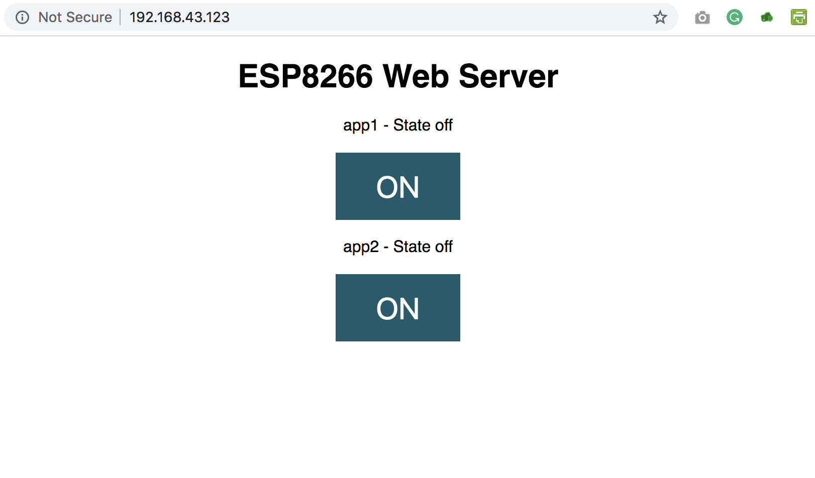
Copy the IP address and paste it in a web browser on any device (Mobile or PC) connected to the same network as the NodeMCU. You should see the web page and be able to toggle the connected appliances by clicking the buttons.
Web Server interface
That’s it for this tutorial. Thanks for reading.
As mentioned above, this tutorial could serve as a building block for more complex web servers and IoT solutions. What will you build?
If you have any question about today’s tutorial, please feel free to share via the comment section.
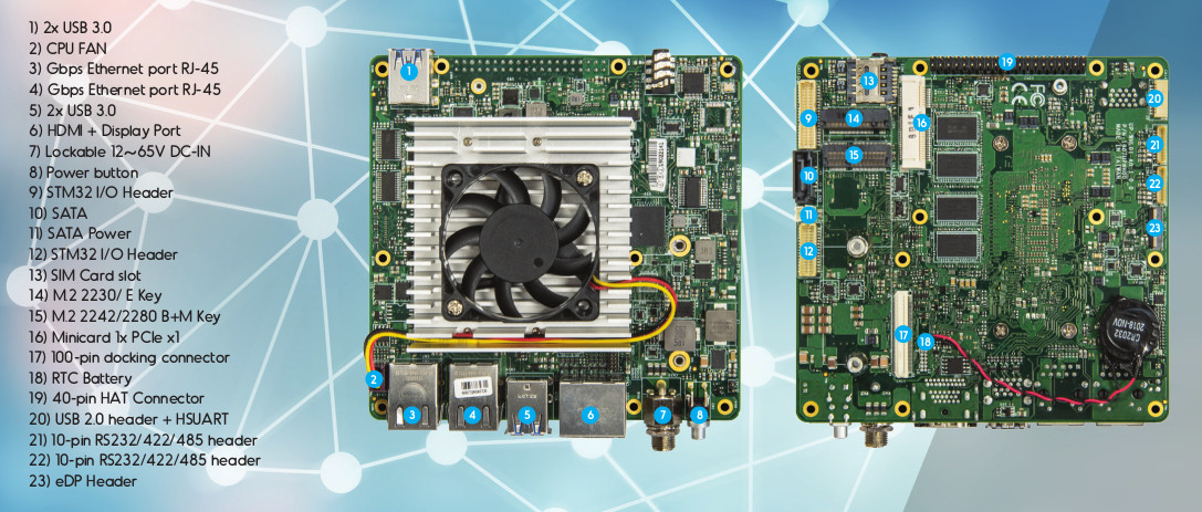
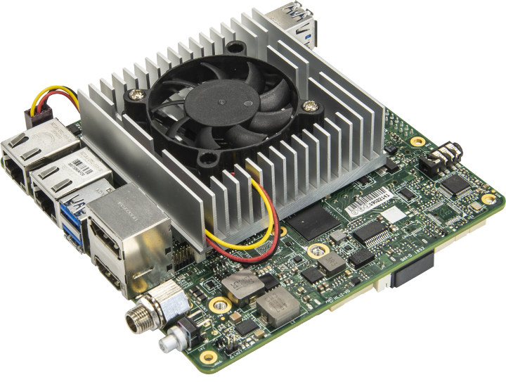
AAEON launched their UP board family back in 2015 with the original board featuring an Atom X5 Cherry Trail processor. Since then they’ve launched more models all based on processors with 10W or lower TDP (Thermal Design Power) such as UP Squared Apollo Lake development board. Now, they have introduced an Intel Core-U series Whiskey Lake processor (15W TDP) based SBC named “UP Xtreme” that will feature some of those Core i3/i5/i7 processors.
Combine the raw power of the 8th generation Core i3, i5 or i7 processor of your UP Xtreme board with AI CORE X. Meet the most complete product family of neural network accelerators for Edge devices. The expansion boards are available in MiniCard/mPCIe, M.2 2242 and M.2 2280. With just a few watts of power consumption, each chip delivers up to four trillion operations per second (TOPS) with a Neural Compute Engine capable of delivering up to one TOPS for the ultimate modern Edge solution.
UP Xtreme specifications:
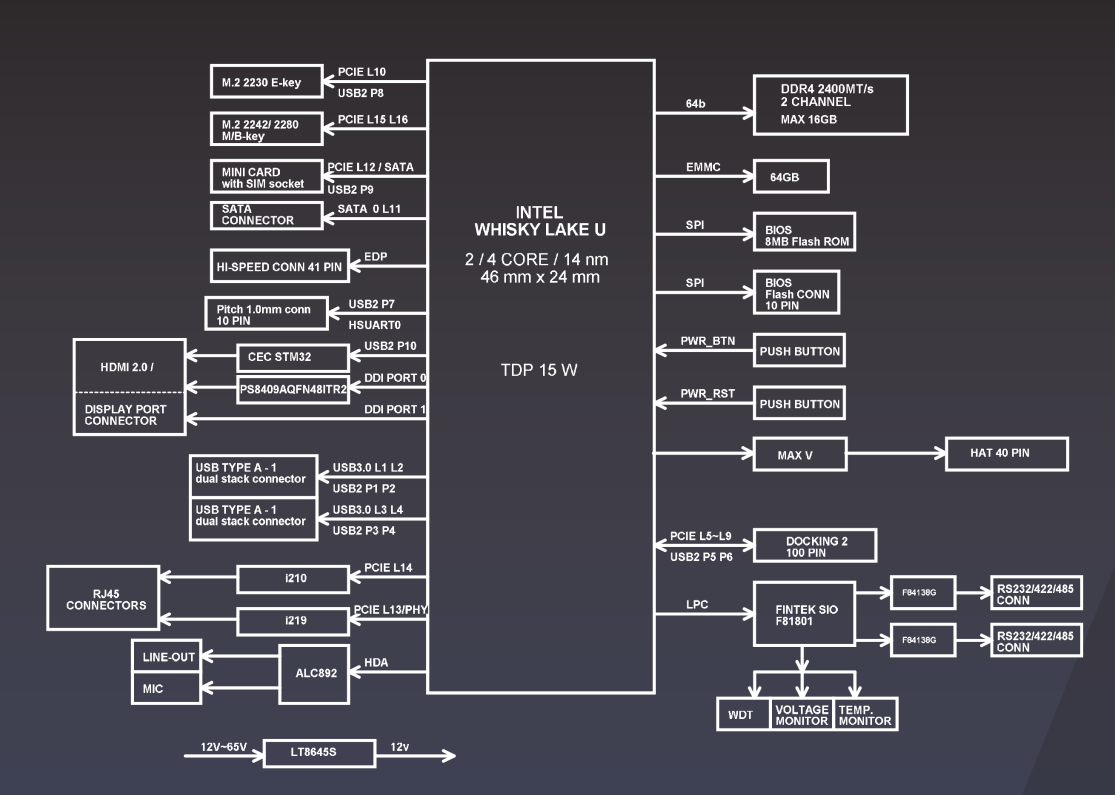
SoC- Intel Dual/Quad Core “Whiskey Lake” Core i3/i5/i7 processor @ 1.8 GHz (Boost frequnecy up to 3.9GHz for i3/i5, up to 4.6 GHz for i7) with Intel UHD graphics 620; 15W TDP
System Memory – Up to 16GB dual-channel DDR4 memory (soldered on-board)
Storage – 16GB to 128GB eMMC 5.1 flash, 1x SATA connector with power connector
Video Output
1x eDP with backlight control header
1x HDMI/DisplayPort Stack connector
Audio – ALC887 for 3.5mm Audio Out/Mic In jack, I2S
Network Connectivity – Dual Gigabit Ethernet via Intel i210/i211, and i219LM PHY’s
USB – 4x USB3.0 ports, 2x USB2.0 ports
Serial Ports – 2x 10-pin RS232/422/485 headers via Fintech F81801
Expansion Slot
1x Minicard with 1x PCIex1 (option mSATA), 1x USB2.0, and SIM card slot
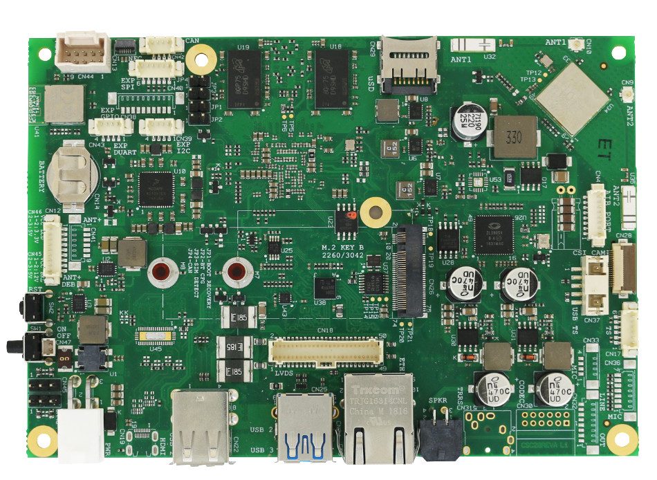
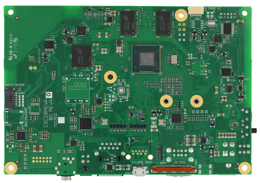
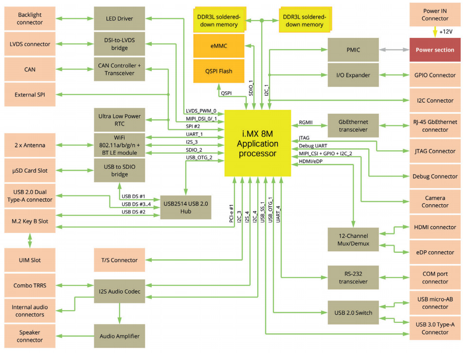
SBC-C20 is an SBC built upon the NXP i.MX 8M Application Processors characterized by HEVC/VP9 decoding in 4Kp60 as well as HDR. As for the memory, it features a DDR3L RAM. Moreover, it provides an optimized IoT stack with preinstalled Wind River Linux 10. The range of connectivity options is particularly broad, with optional Wi-Fi and BT LE 4.2 module, M.2 socket 2 Key B for WWAN modules. Interestingly, it also features a Cortex-M4 for RTOS, the real-time operating system for serving real-time applications that process data as it comes in without buffer delays.
SBC-C20 Back
Specifications listed for the SBC-C20 include:
Processor — NXP i.MX8M Dual, QuadLite, or Quad (2x or 4x Cortex-A53 @ up to 1.5GHz); Vivante GC7000Lite GPU; VPU on all but QuadLite; Cortex-M4F @ 266MHz
Memory/storage:
Up to 2GB DDR3L RAM
Optional up to 16GB eMMC
MicroSD slot
Networking/wireless:
10/100/1000 Ethernet port
Optional WiFi and Bluetooth 4.2 LE
Optional U.FL ant. connectors
M.2 Socket 2 2260 / 3042 Key B slot for WWAN modules
Micro-SIM slot
Media I/O:
eDP port or HDMI 2.0a port for up to 4k@60 with HDR
Optional LVDS for up to 1080p60 with I2C touch support
MIPI-CSI (4-lane)
I2S Audio Codec
Line-out, mic-in via combo TRRS audio jack
Speaker, mic, and earphone headers
Optional 10W amp
Other I/O:
USB 3.0 host port (or USB 2.0 touch controller)
Micro-USB 2.0 OTG port (recovery only)
2x USB 2.0 host ports
RS-232 port
CAN port
Debug UART header
SPI and I2C connectors
8x GPIO
Other features — RTC with battery
Power — 12V DC input
Operating temperature — 0 to 60°C; optional -40 to 85°C
Dimensions — 147 x 101.6mm (3.5-inch)
Operating system — Yocto, Wind River Linux, Android; BSP with wiki
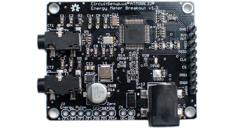
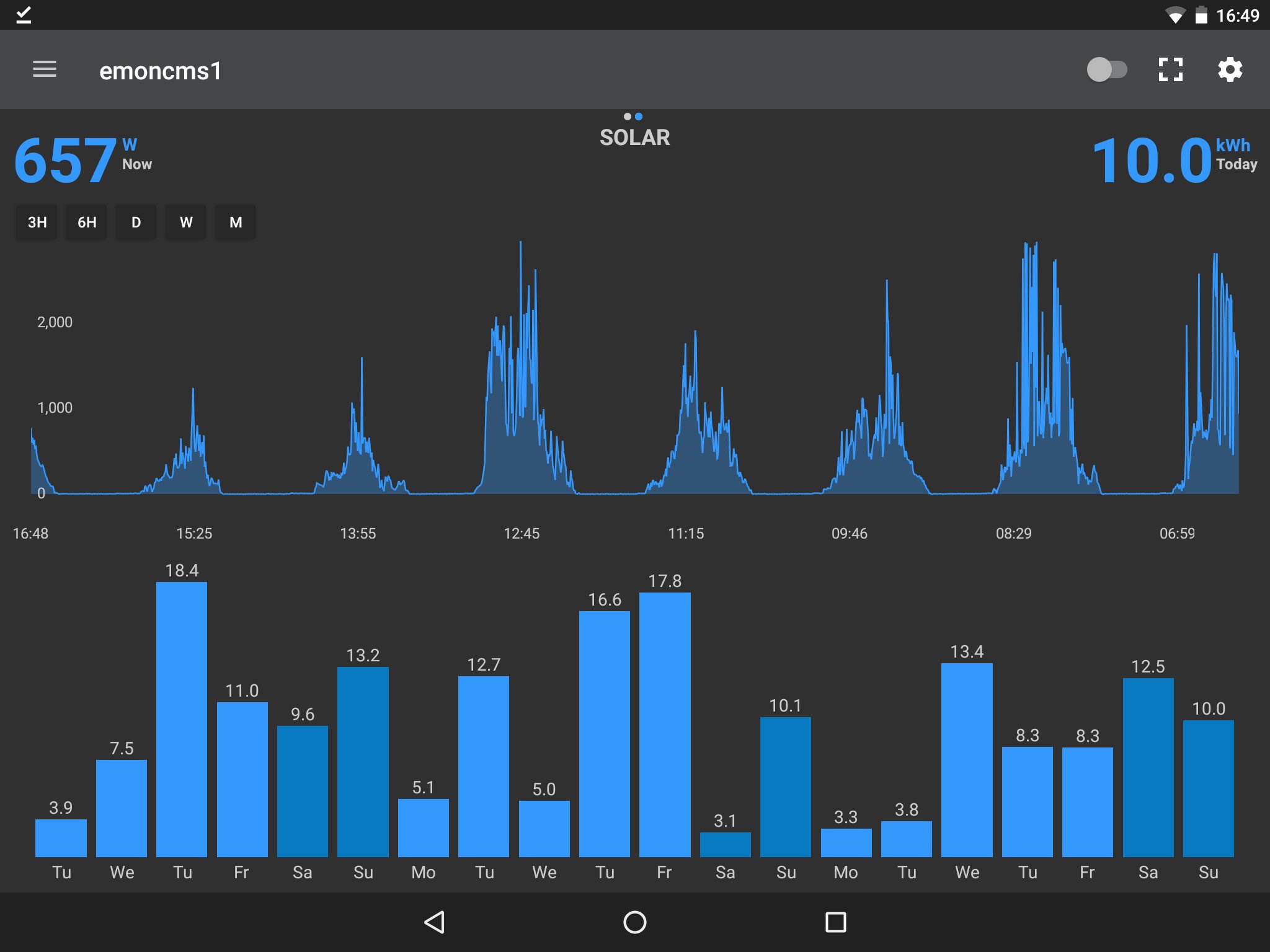
Split Single Phase Energy Meter. Affordable remote energy monitoring for your entire home
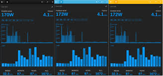
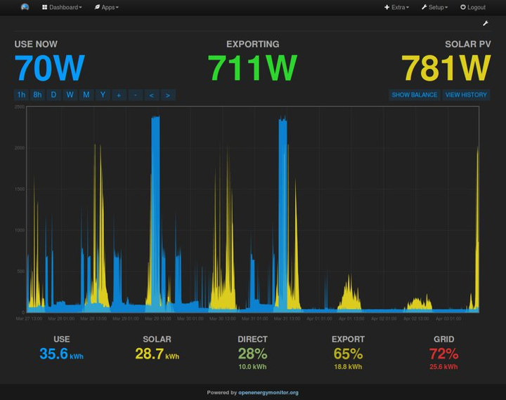
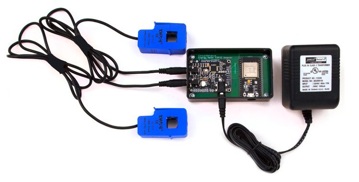
The Split Single Phase Energy Meter can monitor the energy usage in your entire home in real time. It can easily be hooked up to an ESP8266 or ESP32 to wirelessly transmit energy usage data into a program like EmonCMS. It can also be used to monitor solar power generation to keep track of how much power you are making.
EmonCMS Android Screen
With the Split Single Phase Energy Meter you can:
Save Money!
See exactly how much money is being spent on energy in real time
Find appliances that are using too much electricity
View & Gather Energy Data
View the energy usage of your entire home
Or track solar power generation
Review and graph historical energy data
View usage data in the EmonCMS Android or iOS apps
Be Informed!
Independent of your power company’s meter
Set up alerts for over or under usage
Not spend a ton on energy monitoring!
Built to be inexpensive but very accurate
Costs hundreds less than some other solutions
Specifications
Samples two current channels & one voltage channel (expandable to two voltage)
Calculates:
Active Power
Reactive Power
Apparent Power
Power Factor
Frequency
Temperature
Uses standard current transformer clamps to sample current
Includes built-in buck converter to power ESP8266, or ESP32
Two IRQ interrupts, and 1 Warning output
Energy pulse output (pulses correspond to 4 LEDs)
Zero crossing output
SPI Interface
Measurement Error: 0.1%
Dynamic Range: 6000:1
Gain Selection: Up to 4x
Voltage Reference Drift Typical (ppm/°C): 6
ADC Resolution (bits): 16
Compact size at only 40 mm x 50 mm
The project is going to be launched soon on www.crowdsupply.com. For updates, you can subscribe to the form on landing page.
Update 08/05/2019: Split single-phase energy meter just launched on Crowd Supply with a $6,300 funding target. If you only need the energy meter breakout board a $29 pledge will suffice, but most people will likely go with the $59 energy monitoring kit that adds two YHDC SCT-016 120A CT Sensors, a pre-programmed ESP32 module, an ABS plastic box, the adapter board, and mounting screws. The power supply is not included, and can be added for $12 (120V, US only), or you may use your own.
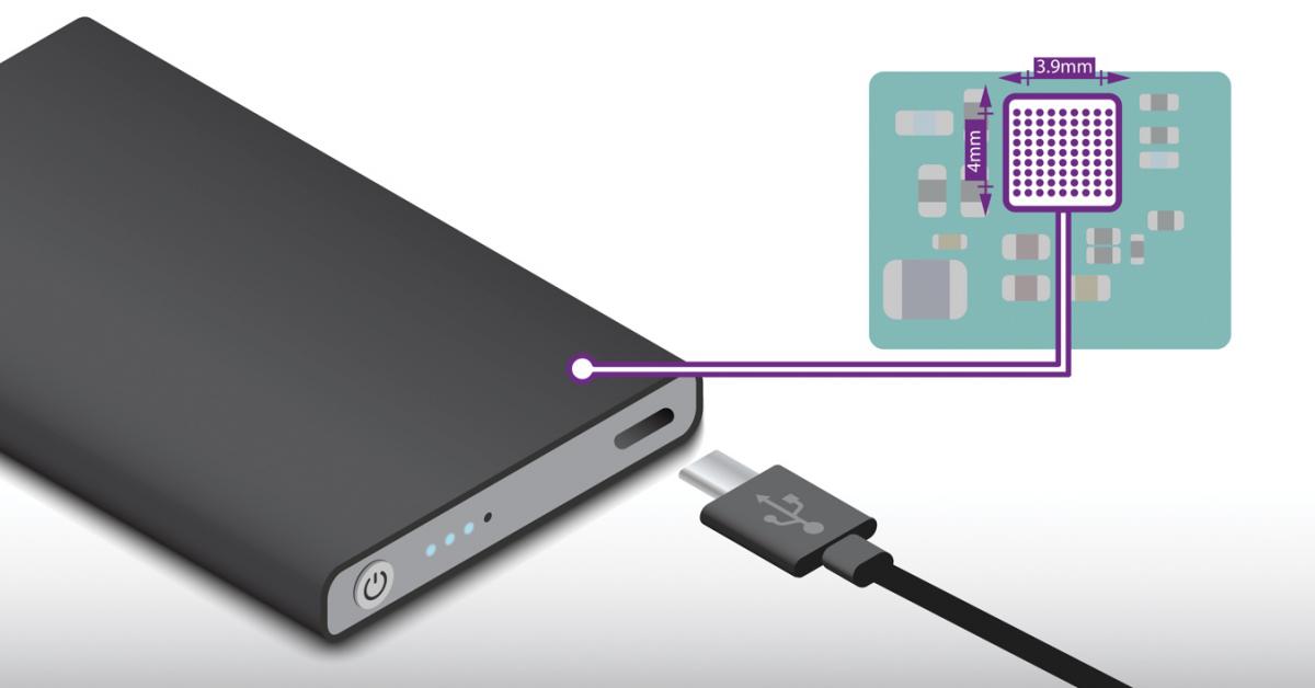
Designers of portable Li-ion battery-powered electronics now have a simplified and more flexible way to add a USB Type-C (USB-C) charging system to their products with the MAX77860 3A switch-mode charger from Maxim Integrated Products, Inc. (NASDAQ: MXIM). This USB-C buck charger provides the industry’s first integrated USB-C port controller and charger to eliminate the need for a separate host controller, simplify software development and reduce overall bill-of-materials (BOM) costs for applications such as financial point-of-sale terminals, power banks, industrial computers, scanners, radios, medical devices, charging cradles, portable speakers and game players.
A wide range of consumer electronic devices are migrating to USB-C interfaces to support rapidly advancing communication and battery-charging capabilities, as well as smaller design size. In current designs, the host microprocessor is needed to detect the current level and configure the charger’s input current limit. While PCs, laptops and cell phones have driven early adoption, USB-C adoption rates are expected to grow at 8.5 percent a year through 2020 thanks to useage in other classes of portable devices, according to IDTechEx.
To reduce design size as well as simplify the system hardware and software design, the MAX77860 integrates USB-C configuration channel (CC) port detection and a battery charger for 15W applications. These integrated functions allow battery charging at the fastest rate possible under the USB-C specification and contribute to 30 percent smaller design size while also simplifying software development. The CC pin detection feature also shortens the design effort by eliminating the need to support end-to-end USB port connection and allowing charging to start automatically.
Key Advantages
Highly Integrated: Eliminates a separate port controller and many discrete components. Reduces the size of an inductor and a capacitor due to a high switching frequency of 2MHz/4MHz, resulting in a solution size that is 30 percent smaller than the closest competitive device. This high level of integration also reduces overall BOM costs.
High Efficiency: High-efficiency buck reduces heat dissipation with more than 93 percent efficiency and up to 3A charging capability.
Design Flexibility: Backward compatibility allows designs to work with both USB-C and legacy BC1.2 or proprietary adapters. Integrated analog-to-digital converter (ADC) frees up resources in the microcontroller, while providing accurate voltage and current measurements.
Commentary
The new MAX77860 from Maxim provides real advantages to design engineers working in the growing internet of things market,” said Kimberly Majkowski, global product manager, Power Management ICs at Premier Farnell. “It reduces cost and design time while delivering super-fast battery-charging capabilities demanded by today’s consumers.
The MAX77860 dramatically reduces system complexity by integrating the charger, the power path, the low-dropout regulator, the ADC and the USB-C CC detection in a small 3.9mm x 4.0mm package,” said Perry Tsao, executive director, Mobile Solutions Business Unit at Maxim Integrated. “This level of integration simplifies the design, enabling the delivery of more power and more functionality in minimal printed circuit board space.
Availability and Pricing
The MAX77860 is available at Maxim’s website for $3.03 (1000-up, FOB USA); also available with select authorized distributors
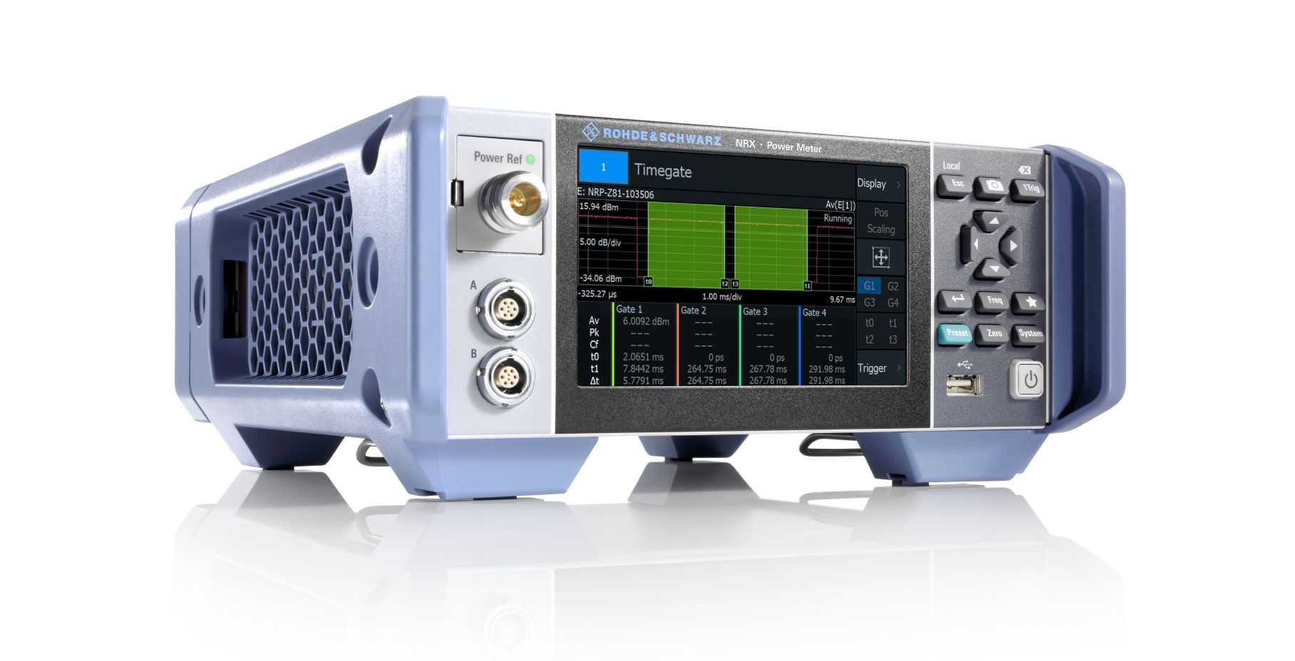
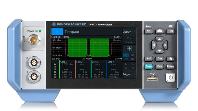
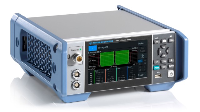
Rohde & Schwarz has equipped the new RF power meter with a touchscreen based operating concept that guides the user through configuration. The R&S NRX has up to four measurement channels, for which Rohde & Schwarz offers a wide range of power sensors. For the first time, both terminating and directional power sensors are supported in a single instrument.
High-precision RF power measurement for modern applications is a challenge. Rohde & Schwarz is launching the R&S NRX on the market so that users can transparently configure their measurements and perform them conveniently. The R&S NRX even makes it possible to perform triggered and synchronized multichannel measurements with different power sensors.
The user operates the instrument via the integrated high-resolution 5″ touchscreen. Measurements are configured using large buttons. The system supports the user with a logical calibration and draws attention to conflicts in case of doubt. If required, the instrument can also be operated using the buttons on its front panel.
The R&S NRX comes as standard with two robust sensor ports, which can be optionally upgraded to four. In addition, sensors can also be connected via USB or Ethernet.
Key Facts
Intuitive operation with touch screen based GUI
Supports up to four R&S®NRP and R&S®NRQ6 power sensors
Supports all sensor-dependent measurement functions
Optional high-precision CW and pulse mode reference source module
Optional power reflection measurements with NRT-Zxx sensors
Wide range of power sensors
The user can connect all terminating power sensors from the Rohde & Schwarz portfolio to the sensor connectors. The R&S NRX-B9 sensor interface module integrates the directional power sensors of the R&S NRT-Z family into the measurement to determine power in both transmission directions.
Reference generator integrated as a module
With the optional R&S NRX-B1 sensor check source module, users can test sensors for a pending measurement. The high-precision 50 MHz/1 GHz reference generator module generates continuous-wave signals as well as pulsed steep-slope signals.
Rohde & Schwarz will present the R&S NRX power meter from March 19 to 21, 2019, at EMV 2019 in Stuttgart (hall C2, booth 619). It is available now from Rohde & Schwarz, and will soon be available from select distributors. The R&S NRX is superseding the proven R&S NRP2 power meter. For more information, visit www.rohde-schwarz.com/ad/press/nrx.
Arrow Electronics and Freelancer.com have worked together to launch ArrowPlus powered by Freelancer.com, a marketplace for electrical and electronics services. By Ally Winning @ eenewsembedded.com
The new platform is intended to close the skills gap by providing companies and individuals with access to over half a million skilled electronic and electrical engineers. ArrowPlus powered by Freelancer is also intended to cut research and development time from years to months through access to a global network of highly diverse technical skills. Arrow’s existing Certified Engineering network will help customers identify the correct people with the skills and experience to fit each requirement.
Freelancer.com is the world’s largest freelancing and crowdsourcing marketplace with more than 32 million users around the world and over 15 million jobs posted in over 1,350 skill areas.
Businesses that need technology help can leverage ArrowPlus powered by Freelancer to find highly qualified experts, and then utilize Arrow technology concierge services to help ensure project success.
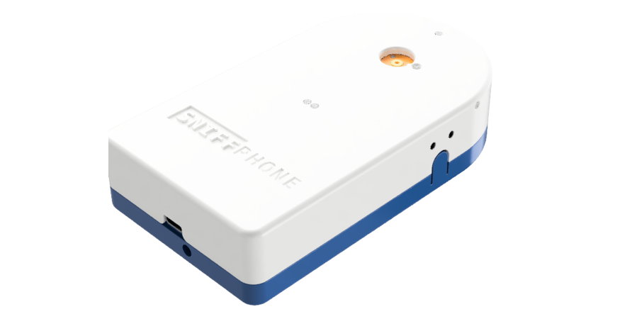
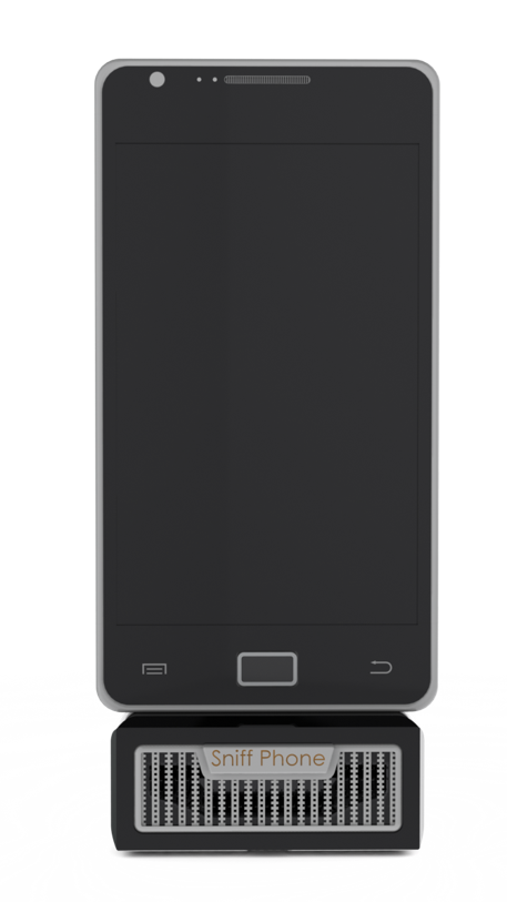
A newly developed handheld medical diagnostic tool called the SniffPhone, analyses exhaled breath and is able to detect early signs of gastric cancer. The SniffPhone links via Bluetooth to a smartphone and is a totally novel application using nanotech chemical sensors, offering enormous benefits to clinicians and patients alike.
Its development has been supported by the Horizon 2020 funding program of the EU. Altogether a total of nine partners have contributed to the development of the device. SniffPhone is held in front of the mouth and the patient exhales to supply a breath sample to the sensor. The device measures volatile organic compounds contained in the sample using highly sensitive nanotechnology chemical sensors. The measurement results are sent via Bluetooth using a smartphone to a dedicated cloud platform where the data can be accessed for analysis and diagnosis by medical staff.
SniffPhone
Electronic diagnosis
This new cancer screening procedure has many advantages over traditional methods. The hand-held device is user-friendly and provides a simple, fast and cost-effective method to detect bio-markers produced by many types of gastro-intestinal conditions. The SniffPhone prototypes have been proven in a series of clinical trials and the team are now looking for financial support to fund production.
The Finnish research centre VTT are one of the project partners; their primary job was to implement the communication links and they are also developing analysis tools to identify high-risk patients for certain medical conditions to assist diagnosis.=